Ed Nisley's Blog: Shop notes, electronics, firmware, machinery, 3D printing, laser cuttery, and curiosities. Contents: 100% human thinking, 0% AI slop.
I’d have trouble faking this with a straight face:
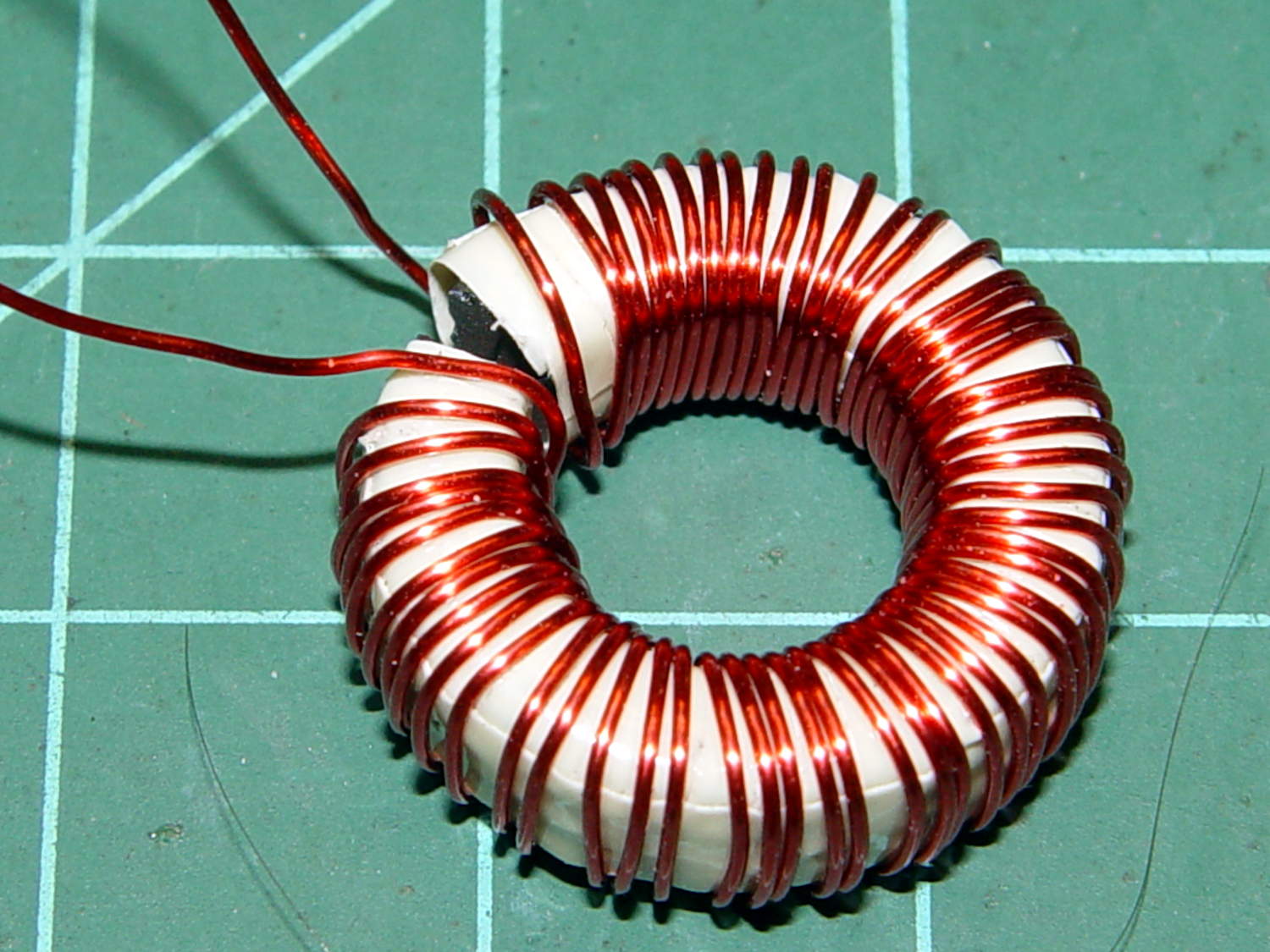
FT82-43 – 56 turns – 24 AWG
That’s measured with the 56 turn winding connected directly to a bench power supply, cranking up the current, taking the reading, and turning the current back down again, so as to avoid cooking the poor thing inside its PLA armor:
FT82-43 toroid – mounted
The “49E” sensor came from one of the bags of eBay fallout. They saturate around 4.25 V; the outputs above 4 V lose their linearity due to the sensor, not ferrite saturation.
The original calculations guesstimates suggested 25 turns would produce full scale at 5 A, so 56 turns should top out at 2.2 A. Frankly, given all the imponderables in this lashup, a factor of two seems pretty close.
Offsetting the output by -1 A would yield a 2 A range that’s just about exactly right. Unfortunately, some fiddling about with neodymium magnets suggests that you (well, I) can’t stuff enough opposing field into the slit without saturating (some part of) the ferrite core, reducing the permeability, and blowing all the assumptions.
So that suggests a buck winding, obviously with more turns to allow less current for the same magnetizing force. Wrapping 110 turns reduces the buck current to 500 mA and assuming a bit over an inch/turn requires 10 feet, which is nearly 1 Ω of 30 AWG wire: the buck current dumps another 250 mW into (a somewhat larger version of) that PLA armor.
Or just throw away half of the Hall effect sensor range and use an op amp along the lines of the LED current sensor.
Given the fragility of ferrite toroids in general and slit toroids in particular, a touch of up-armoring seems sensible:
FT82-43 toroid – mounted
The solid model includes a toroid shell with roughly the right curves:
Toroid Mount – Show layout
That puts a nice rounded shape on the bottom of the armor, not that that makes much difference:
Toroid Mount – Build layout
The central hole passes a 4-40 brass, nylon, or stainless steel screw. Most of the magnetic field stays within the ferrite and, heck, this isn’t a crazy-sensitive analog application, so even an ordinary steel screw shouldn’t cause any particular problems.
The rectangular (not pie-wedge) slit barely passes the Hall effect sensor.
I’ll pour some clear epoxy over the toroid, with tape masking the ferrite core and sealing the ends, to immobilize the windings. That sounds like a good idea after calibration and suchlike.
The OpenSCAD source code, which should be sufficiently parametric that I can crank ’em out for all the other toroids large enough to accept a screw:
// Toroid coil mounting bracket
// Ed Nisley - KE4ZNU - August 2014

Layout = "Mount";			// Coil Mount Build Show

//- Extrusion parameters must match reality!
//  Print with 4 shells and 3 solid layers

ThreadThick = 0.20;
ThreadWidth = 0.40;

HoleWindage = 0.2;			// extra clearance

Protrusion = 0.1;			// make holes end cleanly

AlignPinOD = 1.70;			// assembly alignment pins: filament dia

function IntegerMultiple(Size,Unit) = Unit * ceil(Size / Unit);

//----------------------
// Dimensions

ID = 0;												// subscripts for cylindrical objects
OD = 1;
LEN = 2;

Coil = [10.25,23.50,8.3];							// wound toroid core

SensorThick = 2.0;

BaseThick = IntegerMultiple(1.0,ThreadThick);		// baseplate under coil
WallThick = IntegerMultiple(1.0,ThreadWidth);		// walls beside coil

ScrewHoleDia = 4.0;									// allow alignment slop around 3 mm / #4 screws

//----------------------
// Useful routines

module PolyCyl(Dia,Height,ForceSides=0) {			// based on nophead's polyholes

  Sides = (ForceSides != 0) ? ForceSides : (ceil(Dia) + 2);

  FixDia = Dia / cos(180/Sides);

  cylinder(r=(FixDia + HoleWindage)/2,
           h=Height,
           $fn=Sides);
}

module ShowPegGrid(Space = 10.0,Size = 1.0) {

  RangeX = floor(100 / Space);
  RangeY = floor(125 / Space);

	for (x=[-RangeX:RangeX])
	  for (y=[-RangeY:RangeY])
		translate([x*Space,y*Space,Size/2])
		  %cube(Size,center=true);

}

//----------------------
// Basic coil shape

module CoilShape() {

CornerRadius = min((Coil[LEN] / 2),((Coil[OD] - Coil[ID]) / 2))  / 3;
MidRadius = (Coil[ID] + Coil[OD]) / 4;
HalfX = (Coil[OD] - Coil[ID]) / 4 - CornerRadius;
HalfY = (Coil[LEN] / 2) - CornerRadius;

echo(CornerRadius,MidRadius,HalfX,HalfY);

	color("Goldenrod")
	render(convexity = 2)
		rotate(180/20)
			rotate_extrude(convexity=3,$fn=20)
				translate([MidRadius,0])
					hull()
						for (i=[-1,1],j=[-1,1])
							translate([i*HalfX,j*HalfY])
								circle(r=CornerRadius,$fn=24);
}

//----------------------
// Mount

module Mount() {

	difference() {
		rotate(180/20)
			cylinder(h=(BaseThick + Coil[LEN]),d=(Coil[OD] + 2*WallThick),$fn=20);

		translate([0,0,-Coil[LEN]])							// make screw hole
			rotate(180/6)
				PolyCyl(ScrewHoleDia,3*Coil[LEN],$fn=6);

		translate([0,0,BaseThick + Coil[LEN]/2])			// set bottom curve
			CoilShape();

		translate([0,0,BaseThick + Coil[LEN]])				// clear out top
			CoilShape();

		translate([(Coil[ID]/2 + Coil[OD]/2),0,0])
			cube([Coil[OD],SensorThick,3*Coil[LEN]],center=true);
	}
}


ShowPegGrid();

if (Layout == "Coil") {
	CoilShape();
}

if (Layout == "Mount")
	Mount();

if (Layout == "Show") {
	Mount();
	translate([0,0,(BaseThick + Coil[LEN]/2)])
		CoilShape();
}


if (Layout == "Build") {
	Mount();
}
I’m pretty sure that chip at 1 o’clock happened while it was clamped in the vise between two cardboard sheets, but I haven’t a clue as how it got that much force. In any event, that shouldn’t affect the results very much, right up until it snaps in two.
Although the current will come from a (rectified) 120 VAC source, the winding will support only as much voltage as comes from the IR drop and inductive reactance, which shouldn’t be more than a fraction of a volt. Nevertheless, I wound the core with transformer tape:
FT82-43 toroid – wrapped
That’s 3M 4161-11 electrical tape (apparently out of production, but perhaps equivalent to 3M’s Super 10 tape) cut into half-foot lengths, slit to 100 mils, and wrapped ever so gently.
The thickest offering from the Big Box o’ Specialty Wire was 24 AWG, so that’s what I wound on it:
FT82-43 toroid – wound
That’s 56 turns, which should convert 2.2 A into 1000 G (enough to max out the Hall effect sensor) and is more in keeping with 24 AWG wire’s 3.5 A current rating.
The insulated core requires just under 1 inch/turn, so figure the length at 56 inch. The wire tables show 26.2 Ω/1000 ft, so the DC winding resistance should be 120 mΩ. My desk meter has 0.1 Ω resolution, which is exactly the difference between shorted probes and probes across the coil: close enough.
The inductance is 170 µH, so the inductive reactance at 120 Hz = 128 mΩ.
The motor winding resistance limits the peak current to about 200 V / 40 Ω = 5 A, in the absence of the transistor current limiter, and, if it gets above that, things have gone very, very wrong. Mostly, I expect currents under 1 A and it may be useful to reduce the full scale appropriately.
The cheap eBay “SS49” Hall effect sensors I’m using produce anywhere between 0.9 and 1.8 mV/G; I’ll use 1.4 mV/G, which is at least close to the original Honeywell spec. That allows a bit over ±1000 G around the sensor’s VCC/2 bias within its output voltage range (the original datasheet says minimum ±650 G), so I’ll use B = 1000 G as the maximum magnetic flux density. The overall calibration will be output voltage / input current and I’m not above doing a one-off calibration run and baking the constant into the firmware.
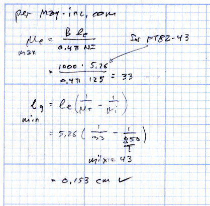
The effective mean path length turns out to be a useful value for a slit toroid:
effective MPL = (toroid MPL - air gap length) + (µ · air gap length)
The SS49 style sensor spec says they’re 1.6 mm thick, and the saw-cut gaps run a bit more, but 1.5 mm will be close enough for now.
The relation between all those values:
B = 0.4 π µ NI / (effective MPL)
Solving for NI:
NI = B · (eff MPL) / (0.4 π µ)
Solving for N:
N = B · (eff MPL) / (0.4 π µ I)
You always round up the result for N, because fractional turns aren’t a thing you can do with a toroid.
The saturation flux density seems to be measured at H = 10 Oe, but that applies to the intact toroids. The air gap dramatically reduces the effective µ, so you must apply a higher H to get the same B in the ferrite at saturation. At least, I think that’s the way it should work.
H = 0.4 π NI / (geometric MPL)
Then:
FT50-61: H = 58 Oe
FT82-43: H = 30 Oe
I’m surely missing some second-order effect that invalidates all those numbers.
Figuring the wire size for the windings:
FT50:
ID = 0.281 inch
Circumference = 0.882 inch
28 turns → wire OD = 0.882/28 = 31 mil
20 AWG without insulation
FT82:
ID = 0.520 inch
Circumference = 1.63 inch
25 turns → wire OD = 1.63/25 = 65 mil
14 AWG without insulation
Of course, the wire needs insulation, but, even so, the FT82 allows a more rational wire size.
Page 4.12 of the writeup from Magnetics Inc has equations and a helpful chart. They suggest water cooling a diamond-bonded wheel during the slitting operation; my slapdash technique worked only because I took candy-ass cuts.
Mulling over how to add a 1/rev sensor to the sewing machine motor, it occurred to me that simply drilling a hole through the pulley would provide a clean optical path and a convenient 2/rev output signal.
However, the OEM pulley doesn’t extend beyond the end of the shaft:
Kenmore 158 – AC drive motor – overview
Rather than drill a hole in the shaft or (attempt to) affix something onto a pulley that spins at 10 kRPM, I figured I should make another pulley and mutilate that.
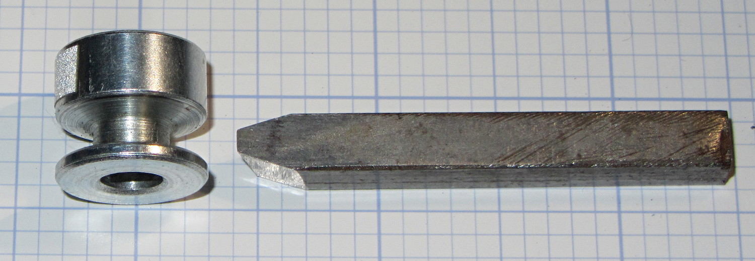
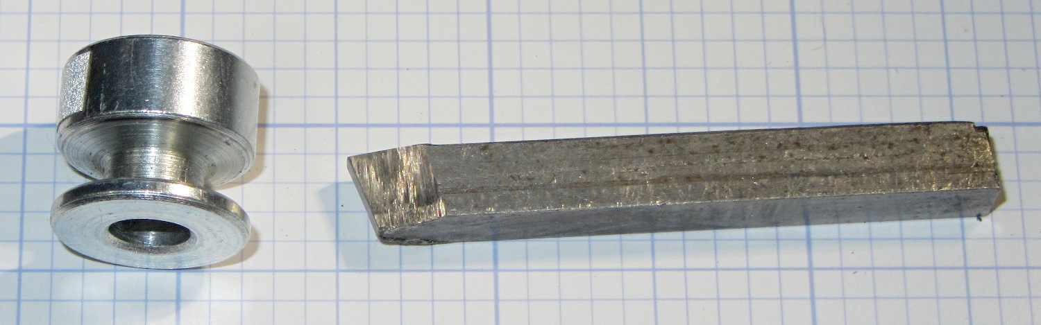
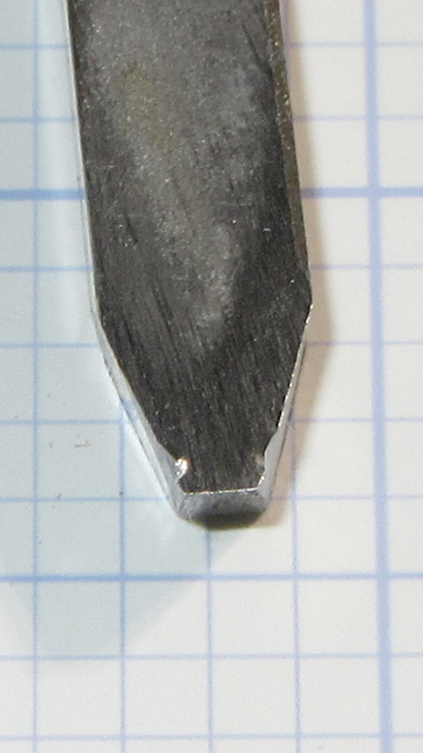
Because this will surely call for more than one new pulley before I get everything right, a lathe form tool seemed in order. Introducing a suitable blank from the Bin o’ 1/4 Inch Bits to Mr. Bench Grinder produced a likely looking candidate, with an included angle of about 35° (a skosh over 17° on each side) and sized just a wee bit narrower than the pulley groove.
From the top:
Pulley form tool – top
From the side:
Pulley form tool – side
Skim the surface of a 5/8 inch rod to match the pulley OD, plunge a cutoff tool to make most of the cut, insert bit in holder, align perpendicular to workpiece, line up to center of cut, slobber on more cutting lube:
Pulley form tool – prepared blank
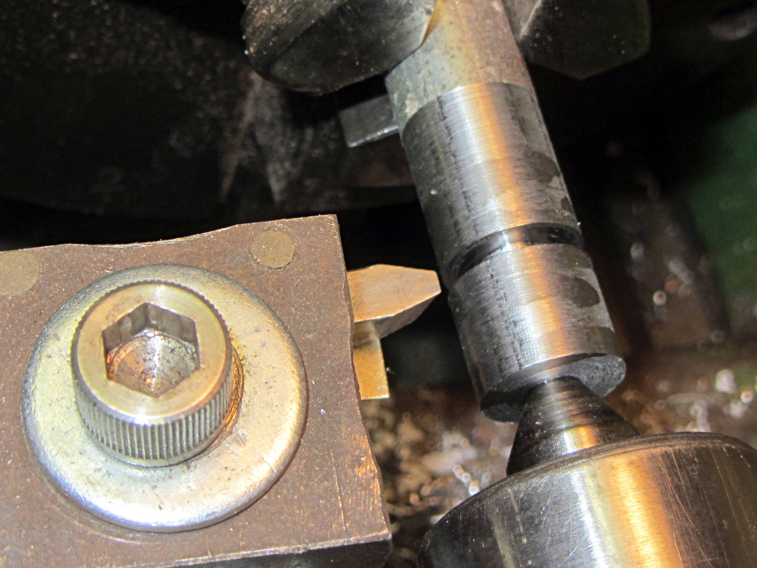
Plunging the tool slowly into the cut produces … no chips … nothing … smoke?
Come to find out that the Bin o’ 1/4 Inch Bits contained not just lathe tool bits & blanks made from tool steel, but one length of 1/4 inch square key stock made from ordinary soft steel:
Pulley form tool – damage
I should have known that from the type of sparks flying off the grinding wheel, right?
You knew that just from looking at the first picture, because a real lathe bit blank wouldn’t be all beat to shit…
Mary recently learned that large spools of thread have a cross-wound lay that should feed over the end, not from the side as do ordinary stack-wound spools. So I built a right-angle adapter that fits over the not-quite-vertical spool pin on the sewing machine and aims directly at the thread tensioner:
Large spool adapter – on sewing machine
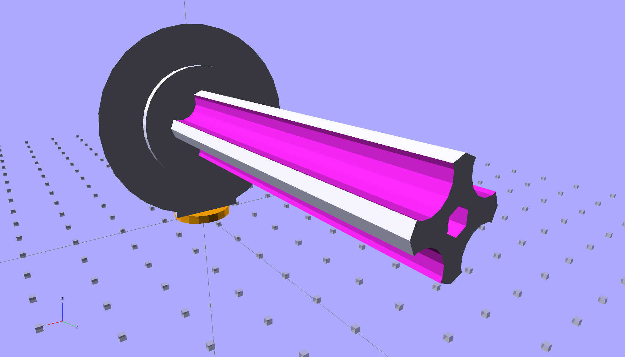
The solid model shows off the fluted rod that passes through the spool:
Large Spool Adapter – solid model – mount
It’s more impressive from the other end:
Large Spool Adapter – solid model – spool end
The first pass at the rod had six flutes, but that seemed unreasonably fine; now it has four. The round base on the rod provides more griptivity to the platform while building and has enough space for the two alignment pins that position it in the middle of the dome:
Large Spool Adapter – solid model – alignment holes
The dome gets glued to the rod base plate:
Large spool adapter – clamped
The spool pin hole is a snug fit around the pin on the sewing machine, because otherwise it would tend to rotate until the spool pointed to the rear of the machine. The fluted rod is a snug friction fit inside the (cardboard) spool. Some useful dimensions:
Spool pin (on Model 158): 5 mm OD, 40 mm tall
Large spool cores: 16 mm ID, 27 mm OD, 70 mm long
I had all manner of elaborate plans to make an expanding fluted rod, but came to my senses and built the simple version first. If that rod isn’t quite big enough, I can build another adapter, just like this one, only slightly larger. The source code includes a 0.5 mm taper, which may suffice.
Back in the day, shortly after the Thing-O-Matic started producing dependable results, one of the very first things I made was a simple adapter to mount large spools on the pin in the most obvious way:
Large spool adapter – old TOM version
Now we all know better than that, my OpenSCAD-fu has grown stronger, and the M2 produces precise results. Life is good!
The OpenSCAD source code:
// Large thread spool adapter
// Ed Nisley - KE4ZNU - August 2014

Layout = "Show";			// Build Show Spindle Spool

Gap = 10.0;					// between pieces in Show

//- Extrusion parameters must match reality!
//  Print with 4 shells and 3 solid layers

ThreadThick = 0.20;
ThreadWidth = 0.40;

HoleWindage = 0.2;			// extra clearance

Protrusion = 0.1;			// make holes end cleanly

AlignPinOD = 1.70;			// assembly alignment pins: filament dia

function IntegerMultiple(Size,Unit) = Unit * ceil(Size / Unit);

//----------------------
// Dimensions

LEN = 0;											// subscripts for cylindrical objects
ID = 1;
OD = 2;

Spindle = [40.0,5.0,14.0];							// spool spindle on sewing machine
Spool = [70.0,16.0,27.0];							// spool core

Taper = 0.50;										// spool diameter increase at base

CottonRoll = [65.0,Spool[OD],45.0];					// thread on spool

Mount = [Spindle[LEN],(Spindle[ID] + 4*ThreadWidth),1.0*Spool[ID]];

Flutes = 4;
Flange = [2.0,Spool[OD],Spool[OD]];

ScrewHole = [10.0,4.0 - 0.7,5.0];					// retaining screw

PinOC = Spool[ID]/4;								// alignment pin spacing

//----------------------
// Useful routines

module PolyCyl(Dia,Height,ForceSides=0) {			// based on nophead's polyholes

  Sides = (ForceSides != 0) ? ForceSides : (ceil(Dia) + 2);

  FixDia = Dia / cos(180/Sides);

  cylinder(r=(FixDia + HoleWindage)/2,
           h=Height,
           $fn=Sides);
}

module ShowPegGrid(Space = 10.0,Size = 1.0) {

  RangeX = floor(100 / Space);
  RangeY = floor(125 / Space);

	for (x=[-RangeX:RangeX])
	  for (y=[-RangeY:RangeY])
		translate([x*Space,y*Space,Size/2])
		  %cube(Size,center=true);

}

//- Locating pin hole with glue recess
//  Default length is two pin diameters on each side of the split

module LocatingPin(Dia=AlignPinOD,Len=0.0) {

	PinLen = (Len != 0.0) ? Len : (4*Dia);

	translate([0,0,-ThreadThick])
		PolyCyl((Dia + 2*ThreadWidth),2*ThreadThick,4);

	translate([0,0,-2*ThreadThick])
		PolyCyl((Dia + 1*ThreadWidth),4*ThreadThick,4);

	translate([0,0,-(Len/2 + ThreadThick)])
		PolyCyl(Dia,(Len + 2*ThreadThick),4);

}

//----------------------
// Spindle

module SpindleMount() {

	render(convexity=4)
	difference() {
		union() {
			resize([0,0,Mount[OD]])							// spool backing plate
				translate([0,CottonRoll[OD]/2,0])
					sphere(d=CottonRoll[OD],center=true);
			translate([0,CottonRoll[OD]/4,0])				// mounting post
				rotate([90,0,0])
					cylinder(d=Mount[OD],h=CottonRoll[OD]/2,center=true);
		}

		translate([0,(2*Mount[LEN] - Protrusion),Mount[OD]/4])				// punch spindle hole
			rotate([90,0,0])
//				PolyCyl(Spindle[ID],2*Mount[LEN],6);
				cylinder(d=Spindle[ID],h=2*Mount[LEN],$fn=6);

		for (i=[-1,1]) {									// punch alignment pin holes
			translate([i*PinOC,CottonRoll[OD]/2,0])
					LocatingPin(Len=Mount[OD]/3);
		}

		translate([0,0,-CottonRoll[OD]])					// remove half toward spool
			cube(2*CottonRoll[OD],center=true);
	}

}

//----------------------
// Spool holder

module SpoolMount() {

	difference() {

		union() {

			translate([0,0,(Flange[LEN] - Protrusion)])
				difference() {
					cylinder(d1=(Spool[ID] + Taper),d2=Spool[ID],h=Spool[LEN],$fn=2*Flutes);						// fit spool ID

					for (a=[0 : 360/Flutes : 360-1])						// create flutes
						rotate(a + 180/Flutes)
							translate([Spool[ID]/2,0,-Protrusion])
								rotate(180/16)
								cylinder(r=Spool[ID]/4,h=(Spool[LEN] + 2*Protrusion),$fn=16);

					translate([0,0,(Spool[LEN] - ScrewHole[LEN])])			// punch screw hole
						PolyCyl(ScrewHole[ID],(ScrewHole[LEN] + Protrusion),6);

				}
			cylinder(d=Flange[OD],h=Flange[LEN]);							// base flange
		}

		for (i=[-1,1])												// punch alignment pin holes
			translate([0,i*PinOC,0])								//  ... orients solid flange up
					LocatingPin(Len=Flange[LEN]);
	}

}


ShowPegGrid();

if (Layout == "Spindle") {
	SpindleMount();
}
if (Layout == "Spool") {
	SpoolMount();
}

if (Layout == "Show") {
	translate([0,Mount[OD]/4,2.0]) {
		rotate([90,0,0])
			SpindleMount();
		translate([0,Gap,CottonRoll[OD]/2])
			rotate([-90,0,0]) rotate(90)
				SpoolMount();
	}
	color("Orange") {
		translate([0,0,2])
			cylinder(d=Spindle[ID],h=Spindle[LEN],$fn=6);
		cylinder(d=Spindle[OD],h=2.0,$fn=18);
	}

}

if (Layout == "Build") {
	translate([-5,0,0])
		rotate(90)
			SpindleMount();
	translate([Flange[OD]/2,0,0])
			SpoolMount();
}
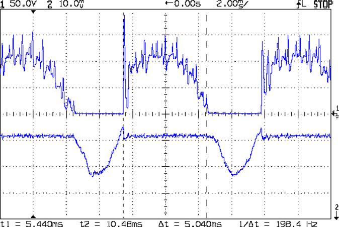
The motor current (200 mA/div) never goes to zero, but the ET227 collector voltage hits zero as the transistor saturates: the motor winding soaks up all the available line voltage and the transistor dissipation drops close to zero. The datasheet suggests VCE(sat) < 0.1 V for IC < 5 A, albeit with IB = 30 A (!).
The ET227 base drive was 77 mA, measured on a better meter than the low-resolution one in the power supply, and the transistor gain works out to 8 = 620 mA / 77 mA along those flat tops.
Eyeballometrically speaking, the dissipation averages 50 W = 90 V x 620 mA during those spiky sections where the transistor must absorb the difference between the line voltage and the motor voltage. The cursors say that takes 5 ms of the 8.3 ms period of the 120 Hz full wave rectified power, so the duty cycle is 42% and the average average dissipation works out to 20 W. That’s still enough to warm up that big heatsink; the motor driver will need a thermal sensor and a quiet fan.
That commutation noise looks pretty scary, doesn’t it?
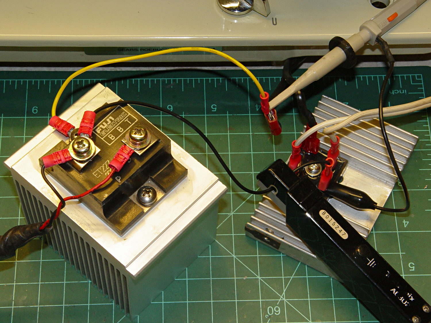
The test setup:
Kenmore 158 – AC motor FW ET227 drive – test setup
The bridge rectifier doesn’t really need a heatsink, but it looked better for a Circuit Cellar picture…