Ed Nisley's Blog: Shop notes, electronics, firmware, machinery, 3D printing, laser cuttery, and curiosities. Contents: 100% human thinking, 0% AI slop.
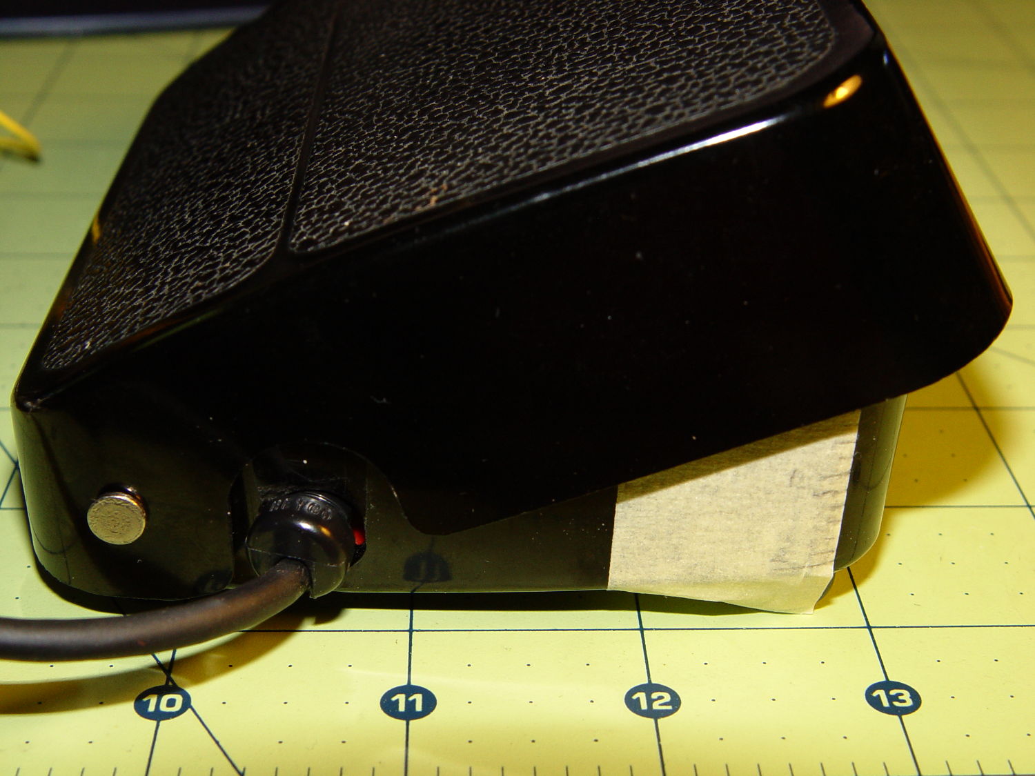
For lack of anything smarter, I marked the Kenmore 158 pedal’s range of motion in 2 mm increments, starting at the top:
Kenmore 158 foot pedal – motion calibration
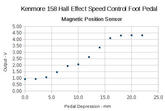
With the Hall effect sensor connected to a +5 V supply, the output looks like this:
Hall sensor output vs pedal depression
The point at 10 mm looks a bit out of place; other than that, the curve is about what you’d expect. The sensor saturates at about 0.84 V and 4.4 V, more or less, so you’re seeing the bias magnet on the low end and the main magnet on the high end.
Obviously, you shouldn’t take these measurements too seriously, but they’re in the right ballpark.
The pivot pin is 75 mm from the base of that line, so the subtended angle is more-or-less 16° = arctan(22/75), which is small enough that plotting the results as a function of the pedal angle doesn’t look any different.
Although you could linearize that, I think the curve has the right shape for a foot pedal speed control: it starts slowly and tapers off smoothly at the high end.
I think I could add a few more millimeters of magnet travel, but this will certainly suffice to get the crash test dummy running.
Given the troubles we’ve had with that thing, using it as an input device isn’t going to happen.
More modern “digital” sewing machines seem to use linear potentiometers or analog optical sensors; retrofitting that old housing seems difficult, at best, because the actuator has barely 15 mm of travel. I’m sure somebody could conjure up a bell crank to amplify the mechanical motion, but that ain’t me.
This doodle shows the rudiments of an alternative:
Hall effect distance sensor – original doodle
The general idea is to have the existing cross bar / roller move a magnet relative to an analog Hall effect sensor: closer to sensor = higher magnetic field = higher sensor output voltage. Ideally, the magnet provides enough field to max out the sensor just before the pedal reaches the limit of its travel, so the magnet never quite touches the sensor.
An optical wedge would serve a similar function, but this pretty much eliminates all the critical alignment & focusing & friction issues. Plus, I have a bunch of analog Hall effect sensors…
I have a stock of telescoping brass tubing, so the inner tube slides over the 4 mm screw that threads into the existing hardware, replacing the old shaft. That tube slides inside an outer tube that’s aligned in a block attached to the pedal frame; an epoxy blob holds it in position. The inner tube should have a nut on the left end to allow adjusting the rest position.
The Hall effect sensors have a zero-field bias at about VCC/2, so a smaller opposing (and fixed) bias magnet on the far side of the sensor pushes the output voltage to the lower limit. The adjusting screw on that side sets the bias level, if that’s needed.
A spring that’s not shown pushes the cross bar away from the block holding the outer tube and sensor; that’s what restores the magnet to its rest position when the pedal is up.
This being the age of rapid prototyping:
Foot Control Sensor Mount – solid model – top
The bottom view shows an opening for the epoxy blob halfway between the rear wall and the opening for the magnet and Hall effect sensor:
Foot Control Sensor Mount – solid model – bottom
Two bosses inside the pedal base fit into those rectangular cutouts, with the centerline of the tubing at the top of the bosses.
The inner brass tube holds the outer tube in the proper alignment while the epoxy slab cures:
Kenmore 158 – Hall speed control – tubing fit
Fortunately, two of the neodymium magnets in my collection worked out perfectly as the main and bias magnets. The smaller bias magnet just barely saturates the output when epoxied to the back of the sensor and the larger magnet has about 15 mm of active range.
The assembly sequence required half a dozen separate epoxy applications; I used quick-curing clear epoxy, rather than my usual JB Weld, because this isn’t the place for a steel filled epoxy. The final step put a washer on the back of the inner tube to hold the spring in place, with the Hall effect sensor invisible under the wad of closed-cell foam at the bottom:
Kenmore 158 – Hall speed control – epoxy curing
The spring comes from the Big Box o’ Medium Springs, which contains a few more just like it.
That solid model and the OpenSCAD code below include several refinements that don’t appear in the photos. In particular, the graceful slope on the top front will look a whole lot better than the abrasive adjustment required to fit the chunky first version into the pedal case:
Kenmore 158 – Hall speed control – prototype interior
On the other paw, that’s what rapid prototyping is all about. I had no way to measure that dimension, but building one to figure it worked pretty well.
Things that may / will need tweaking:
The centerline of the tubing lies on the same plane as the tops of the bosses under those three screws, but the bosses are not particularly flat. Perhaps some setscrews to fine-tune the height and front-to-back tilt angle?
The sketch had adjustable magnet positions; the as-built hardware doesn’t. It’s not clear they’re needed, although that depends on having exactly the right magnets.
The screws are #4 sheet metal and fit nicely into the metric holes; the original screws held a thin aluminum bracket in place, not that chunky block. I could recess the heads, but …
A 3D printed clamp holding the cable and strain relief bushing in place would be cuter than the sheet metal strap I bashed from scrap.
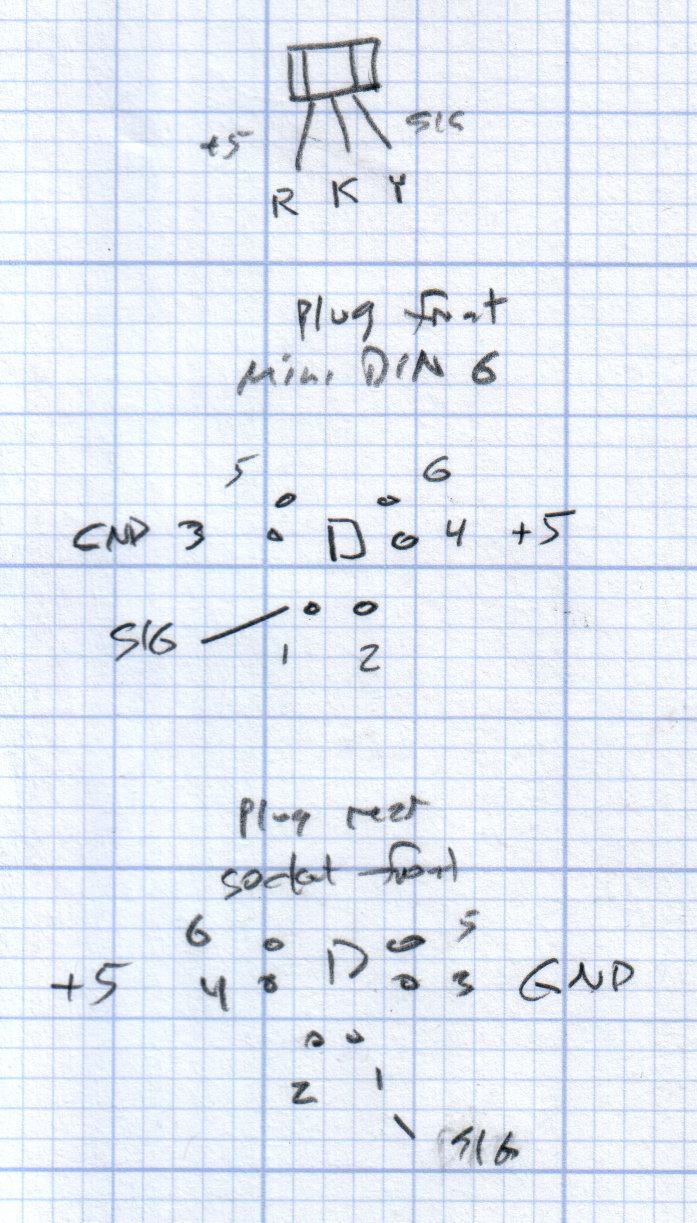
The far end of the cable terminates in a 6-pin mini-DIN connector, left over from the days when PCs (remember PCs?) had PS/2 mice & keyboards:
Kenmore 158 Improved Speed Control Pedal – cable wiring diagram
I’ll eventually put the emitter resistor into the circuit; these sensors work fine without it. The cable provides electrostatic shielding and I’m hoping the impedance is low enough that the motor won’t induce any noise. In any event, some low-pass filtering won’t slow down the response enough to notice.
Next, some measurements…
The OpenSCAD source code:
// Foot Control Sensor Mount
// Ed Nisley - KE4ZNU - June 2014

Layout = "Show";			// Plate Build Show

//- Extrusion parameters must match reality!
//  Print with 4 shells and 3 solid layers

ThreadThick = 0.20;
ThreadWidth = 0.40;

HoleWindage = 0.2;			// extra clearance

Protrusion = 0.1;			// make holes end cleanly

AlignPinOD = 1.70;			// assembly alignment pins: filament dia

function IntegerMultiple(Size,Unit) = Unit * ceil(Size / Unit);

//----------------------
// Dimensions
// Origin at center front edge of plate
//  Z = bottom surface

PlateSize = [85.0,53.0,15.0];						// overall plate size
MidZ = PlateSize[2]/2;								//  height of spring midline
PlateCornerRadius = 1.5;

FrontBevel = [0.0,15.0,5.5];						// Y from front, Z from centerline

ScrewHolesOC = [[-75.0/2,(37.0 - 14.0/2)],[-75.0/2,(37.0 + 14.0/2)],[75.0/2,37.0]];
ScrewHoleDia = 4.0;									// allow alignment slop around 3 mm / #4 screws

BossSize = [[12.0,28.0],[12.0,27.0]];				// mounting bosses: L R
BossOC = [[-75.0/2,37.0],[75.0/2,37.0]];

Stroke = 15.0;										// foot pedal actuation distance

Bushing = [5.6,23.0];								// outer brass tube
MainMagnet = [10.0,5.0];							// magnet on pushrod
BiasMagnet = [5.0,2.0];								// bias magnet behind Hall effect sensor
Spring = [9.0,8.0];									// recess for pushrod retracting spring
Washer = [10.0,1.0];								// recess for washer atop pushrod

OD = 0;												// subscripts for cylindrical objects
LEN = 1;

SensorThick = 2.0;									// Hall effect sensor on bias magnet
FilletLength = 0.75;								// glue fillet on main magnet

//----------------------
// Useful routines

module PolyCyl(Dia,Height,ForceSides=0) {			// based on nophead's polyholes

  Sides = (ForceSides != 0) ? ForceSides : (ceil(Dia) + 2);

  FixDia = Dia / cos(180/Sides);

  cylinder(r=(FixDia + HoleWindage)/2,
           h=Height,
           $fn=Sides);
}

module ShowPegGrid(Space = 10.0,Size = 1.0) {

  RangeX = floor(100 / Space);
  RangeY = floor(125 / Space);

	for (x=[-RangeX:RangeX])
	  for (y=[-RangeY:RangeY])
		translate([x*Space,y*Space,Size/2])
		  %cube(Size,center=true);

}

//----------------------
// Basic plate shape

module Plate() {

R = PlateCornerRadius;
Px = PlateSize[0]/2 - R;
Py = PlateSize[1] - R;
Sides = 4*4;

BevelAngle = atan2((MidZ - FrontBevel[2]),FrontBevel[1]);

echo("Bevel angle: ",BevelAngle);

	difference() {
		linear_extrude(height = PlateSize[2]) {
			hull() {
				translate([-Px,Py])
					circle(r=R,$fn=Sides);
				translate([Px,Py])
					circle(r=R,$fn=Sides);
				translate([Px,R])
					circle(r=R,$fn=Sides);
				translate([-(20-R),R])			// avoid left front boss
					circle(r=R,$fn=Sides);
				translate([-Px,20+R])			// avoid left front boss
					circle(r=R,$fn=Sides);
			}
		}

		translate([0,0,-Protrusion])						// screw bosses
			linear_extrude(height = (MidZ + Protrusion),convexity=2)
				for (i=[0:1])
					translate(BossOC[i])
						square(BossSize[i],center=true);

		translate([0,0,-Protrusion])						// plate mounting screws
			linear_extrude(height = 2*PlateSize[2] + Protrusion,convexity=3)
				for (i=[0:2])
					translate(ScrewHolesOC[i])
						rotate(180/6)
							circle(d=ScrewHoleDia,$fn=6);

		translate([0,0,MidZ + FrontBevel[2]])		// Front bevel
			rotate([BevelAngle,0,0])
				translate([0,0,PlateSize[2]])
					cube(2*PlateSize,center=true);

	}
}

//----------------------
// Modify plate for position sensor hardware

module Sensor() {

GluePort = [1.5*Bushing[OD],Bushing[OD]/2,PlateSize[2]];	// port for glue anchor around bushing

MagnetPort = [1.5*MainMagnet[OD],
			  (Stroke + MainMagnet[LEN] + FilletLength + SensorThick),
			  (PlateSize[2] + 2*Protrusion)];

	difference() {
		Plate();

		translate([0,(PlateSize[1] - Bushing[LEN] - Protrusion),MidZ])		// bushing
			rotate([-90,0,0])
				cylinder(d=Bushing[OD],h=PlateSize[1],$fn=6);

		translate([-GluePort[0]/2,										// bushing anchor opening
				  (PlateSize[1] - 0.66*Bushing[LEN] - GluePort[1]/2),
				  MidZ - GluePort[2] + Bushing[OD]/2])
			cube(GluePort,center=false);

		translate([0,(PlateSize[1] - Bushing[LEN] - MagnetPort[1]/2),MagnetPort[2]/2 - Protrusion])
			cube(MagnetPort,center=true);

		translate([0,(PlateSize[1] - Bushing[LEN] - MagnetPort[1] + Protrusion),MidZ])
			rotate([90,0,0])
				PolyCyl(BiasMagnet[OD],BiasMagnet[LEN] + Protrusion,6);

		translate([0,(PlateSize[1] + Protrusion),MidZ])
			rotate([90,0,0]) rotate(180/8)
				PolyCyl(Spring[OD],Spring[LEN] + Protrusion,8);

		translate([0,(PlateSize[1] + Protrusion),MidZ])
			rotate([90,0,0]) rotate(180/8)
				PolyCyl(Washer[OD],Washer[LEN] + Protrusion,8);

	}
}

ShowPegGrid();

if (Layout == "Plate") {
	Plate();
}

if (Layout == "Show")
	Sensor();

if (Layout == "Build") {
	translate([0,PlateSize[1]/2,PlateSize[2]])
		rotate([180,0,0])
			Sensor();
}
Stuffing the AC motor back into the Kenmore Model 158 crash test dummy sewing machine, tightening the belts, powering it from the bench supply, and recording speed vs. voltage produces this interesting graph:
Kenmore Model 158 AC Motor on DC – Loaded and Unloaded RPM vs Voltage
The blue curve comes from the unloaded motor sitting bare on the bench. The red curve represents a more useful situation, with the motor driving the sewing machine’s main shaft, moving the needle carrier, spinning the bobbin housing, rotating a bunch of cams, and shoving the cranks. I expect the load would be higher while it’s actually punching thread into fabric / zigzagging / whatever, but probably less than a factor of two.
The sewing machine’s top speed is around 8500 rpm, useful only for bobbin loading. Feeding that speed into the linear fit equation and turning the crank backwards says the motor would run from (wait for it) 99.5 V. The motor’s rating is 110 to 120 VAC, so it’s within 10%; that’s ignoring the whole AC vs. DC discussion and my relatively imprecise measurements.
The motor draws about 300 mA unloaded and 500 mA loaded; those values remain essentially constant at all speeds. The loaded current increases by about 10% over the speed range, likely due to increasing mechanical load / windage losses inside the sewing machine.
The locked rotor current is 880 mA at 40 and 45 V, rising to 1 A at 50 V.
The bench supply has an adjustable current limit that steps in 30 mA increments. Starting with the supply in constant voltage mode, reducing the current by 30 mA from the free running value brings the motor to a gradual stop. As with all motors, the output torque comes from the winding current, but in a (series-wound) universal motor the same current energizes both the rotor and the stator windings: there’s a square-law positive feedback loop ending in a high current stall or a low current runaway.
The usual triac speed control will not be useful in this situation, because it will generate an unacceptable level of audible noise.
Closing the feedback loop through the operator’s foot on the pedal works surprisingly well, due to the relatively slow motor response. Duplicating that with, oh, say, an Arduino might require a bit more than just a PID loop.
A picture from a previous repair shows the foot pedal’s innards:
Foot control – inside view
The top cover pivots on small studs that lock into the front of the case. A projection on the cover passes behind the bar near the top of the picture and presses the roller forward as the cover pivots downward under foot pressure.
The bar has an absolute maximum travel of about 15 mm, although it’s impossible to measure in situ with the cover in place:
Kenmore 158 foot pedal – actuating roller
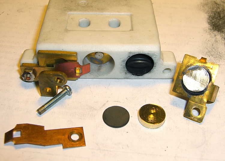
The shaft in the middle of the carbon rheostat aligns the bar and actuates the full-speed switch contacts on the far right (not shown here). The compression spring vanishing into the ceramic body pushes the bar back against the projection on the top cover and ensures the whole affair turns off with the pedal released. The brass plate connects the two carbon buttons on the ends of the disk piles, which is what controls the motor speed from low to high, with the conical spring applying pressure to the piles as the bar moves forward:
Kenmore 158 – carbon-pile speed control – detail
The conical spring compresses about 4 mm after the brass plate contacts the buttons and has about 2 mm of overtravel after the shaft touches the full-speed contacts.
The carbon rheostat in the crash test dummy machine’s foot pedal works better than the much-repaired one from Mary’s machine, with smoother low-speed control and slower starts.
The resistance varies from about 1 kΩ with the most gentle of button touches down to about 30 Ω just before the full-speed contacts close. That’s across 4 mm of travel, so it’s rather sensitive. Most of the range seems to produce 300 to 50 Ω, more or less, kinda-sorta.
Which explains why my repairs were unavailing: the carbon piles must produce the proper resistances as the bar travels over that short distance. Changing the pile length, as happens when the disks erode and I rebuild parts, changes the resistance.
The unloaded motor draws about 300 mA regardless of the applied voltage, which suggests that the motor really wants to see a variable resistance, not a current source. More measurements are needed…
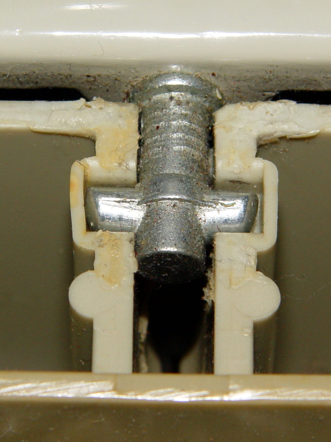
The entire Kenmore Model 158 sewing machine tilts on a pair of pivots extending from the rear of the base, just below the top surface. Mary’s slightly more recent machine has all-steel pivots:
Kenmore 158 – steel pivot pin
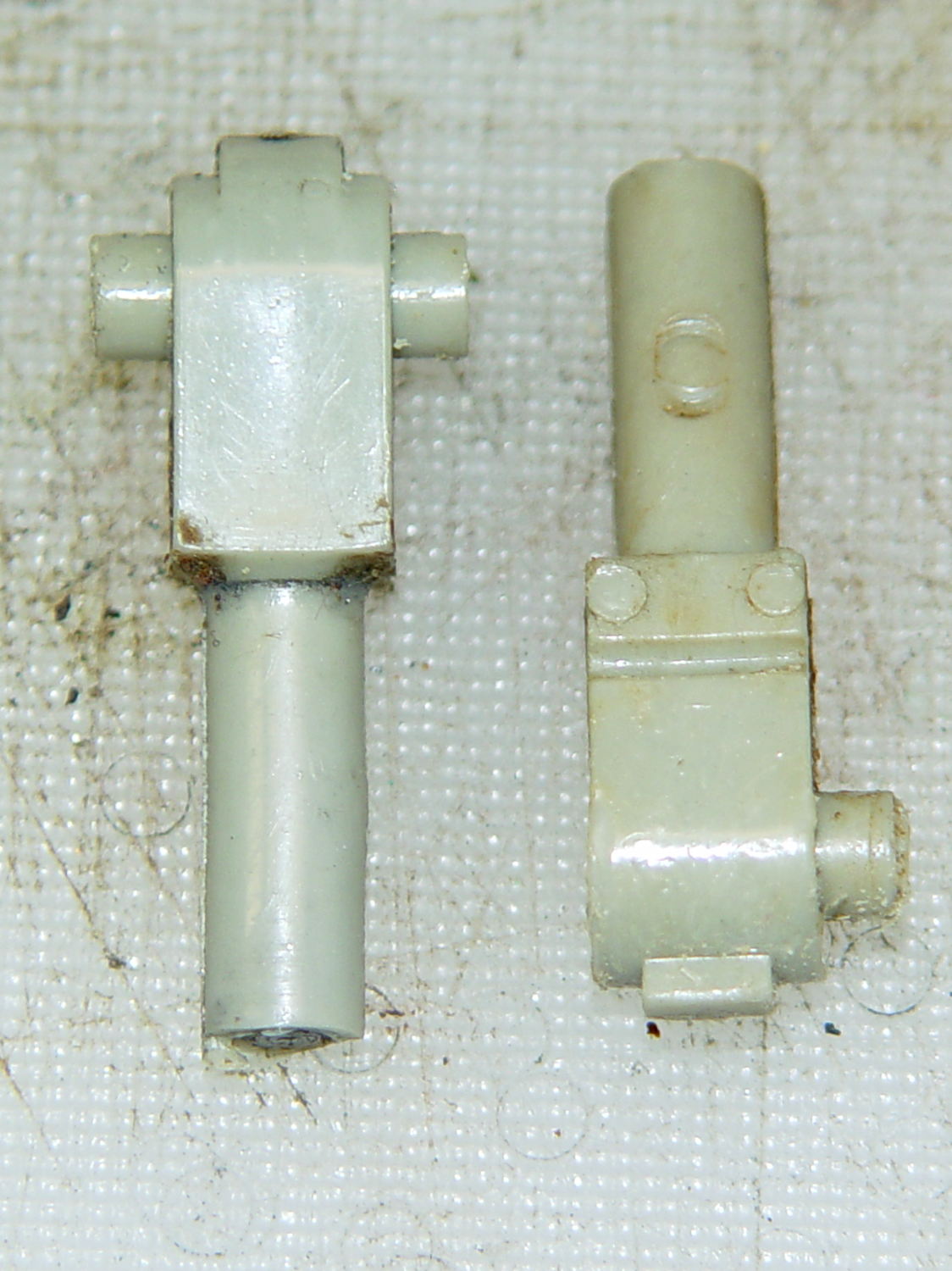
The older crash test dummy machine has two-part pivots, with a plastic housing molded around a steel pin:
Kenmore 158 – plastic pivot pins
Obviously, plastic was the wrong material for the cross pins that rest in the base, leading to the all-steel redesign. Sears no longer stocks replacement parts for those pins, sooo …
Both machines have a large plastic base that’s gradually disintegrating. The plan is to embed the machine frames in countertops, with those cross pins resting on plastic plugs set flush with the surface.
The frame sockets aren’t quite 1/4 inch in diameter; the rest of the hardware uses hard metric sizes, so they’re most likely 6 mm. A 15/64 inch (5.95 mm) drill bit fits snugly and a length of 0.228 inch (5.79 mm) drill rod fits loosely. The round pins are 18 mm long from the shoulder.
The square section is 8.5 mm wide, 9.5 mm tall, and 16 mm long. I have no idea what that mysterious tab on the end is supposed to do.
The cross pins are 5 mm diameter, a scant 15 mm end-to-end, stand 3 mm proud of the central block, and are centered 11 mm out from the edge of the block. I’d make them longer, to distribute the machine’s weight over more of the plugs in the countertop when it’s tilted back.
I can’t duplicate the newer forged steel pins and, for sure, they’re not good candidates for 3D printing. Perhaps:
Saw off 16 mm of 3/8 inch (9.5 mm) square stock
Blind drill 16/64 inch for the 0.228 main pin
Cross drill #12 for a 3/16 inch pin
Epoxy everything together
File off the sharp edges
For the moment, the crash test dummy sits happily on the three legs that the designers thoughtfully cast into its frame.
The handwheel on the Kenmore Model 158 sewing machine has a shiny knurled knob in the middle:
Kenmore 158 handwheel – knob
Turning the knob clockwise screws the knob inward and clamps a friction clutch that locks the handwheel to the main shaft; the motor belt drives the handwheel, the handwheel drives the shaft, and the shaft drives everything inside the sewing machine.
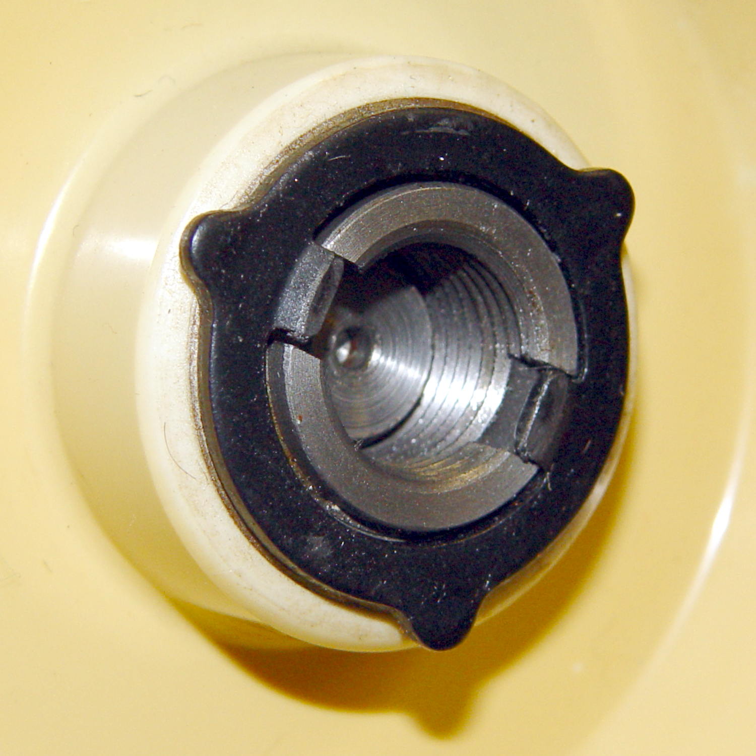
Remove the small screw, turn the knob counterclockwise to remove it, and you see the clutch:
Kenmore 158 – handwheel clutch – detail
Yes, the black stamped metal part is the clutch.
Those three projections around the exterior limit the knob’s travel to a bit under 1/3 turn, with the little screw you just removed traveling between two of the projections. When you reinstall the knob:
Turn it until it’s snug
Insert and tighten the screw
Done!
The two dogs in the middle project outward from the shaft notches: the bases engage the notches and the tips bear on the knob’s inner surface. Tightening the knob pushes on the dogs, presses the clutch against the handwheel, and locks everything together.
It’s entirely possible to install the clutch backwards and, while it’ll come pretty close to working, it’s not quite right.
Update: A note from a reader suggests the machine can struggle along with a backwards clutch for a while:
Just wanted to say thanks for the post on the Kenmore 158 clutch washer. I was trying to hem some jeans, and the clutch was slipping going through the thicker parts. Figured out the washer was on backwards from your post. Now, it works properly.
Having a NEMA 23 stepper fit almost exactly into the spot vacated by the sewing machine’s AC motor was too good to pass up:
Kenmore 158 – NEMA 23 stepper – on adapter
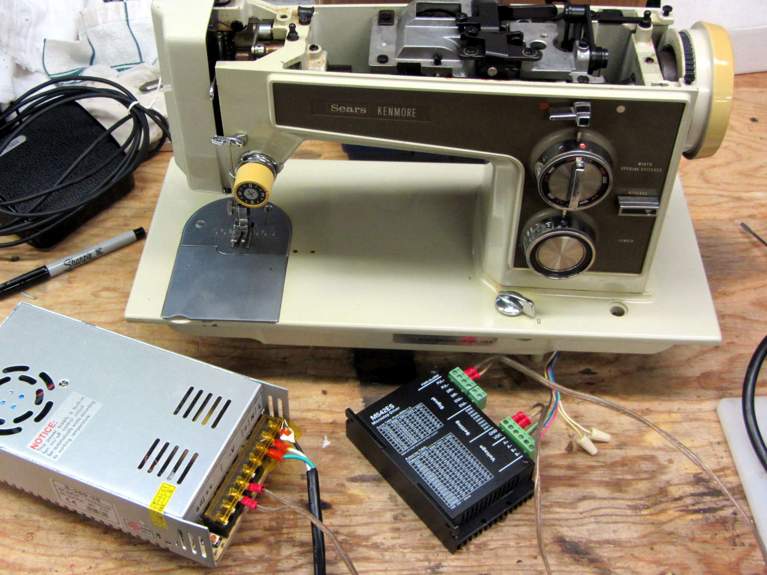
So I wired a power supply to an M542 stepper driver brick, connected the pulse output of a function generator to the brick’s STEP inputs, swapped motor leads until it turned the proper direction (CCW as seen from the shaft end), and turned the function generator knob:
Kenmore 158 – NEMA 23 stepper test
The object was to find the step frequency where the motor stalls, for various winding currents and supply voltages. The motor won’t have enough torque to actually stitch anything near the dropout speed, but this will give an indication of what’s possible.
With a 24 V DC supply and 1/8 microstepping (40 k step/s = 1470 RPM):
1.00 A = 11 k step/s
1.91 A = 44 k/s
2.37 A = 66 k/s
3.31 A = 15 k/s
With a 36 V DC supply and 1/8 microstepping:
1.91 A = 70 k/s
3.31 A = 90 k/s
With a 36 V DC supply and 1/4 microstepping (40 k step/s = 2900 RPM):
1.91 A = 34 k/s
2.37 A = 47 k/s
2.84 A = 47 k/s
3.31 A = 48 k/s
The motor runs faster with a higher voltage supply, which is no surprise: V = L di/dt. A higher voltage across the winding drives a faster current change, so each step can be faster.
The top speed is about 3500 RPM; just under that speed, the motor stalls at the slightest touch. That’s less than half the AC motor’s top speed under a similarly light load and the AC motor still has plenty of torque to spare.
90 k step/s at 1/8 microstepping = 11 k full step/s = crazy fast. Crosscheck: 48 k step/s at 1/4 microstepping = 12 k full step/s. The usual dropout speed for NEMA 23 steppers seems to be well under 10 k full step/s, but I don’t have a datasheet for these motors and, in any event, the sewing machine shaft provides enough momentum to keep the motor cruising along.
One thing I didn’t expect: the stepper excites howling mechanical resonances throughout its entire speed range, because the adapter plate mounts firmly to the cast aluminum frame with absolutely no damping anywhere. Mary ventured into the Basement Laboratory to find out what I was doing, having heard the howls upstairs across the house.
She can also hear near-ultrasonic stepper current chopper subharmonics that lie far above my audible range, so even if the stepper could handle the speed and I could damp the mechanics, it’s a non-starter for this task.
Given that the AC motor runs on DC, perhaps a brute-force MOSFET “resistive” control would suffice as a replacement for the carbon disk rheostat in the foot pedal. It’d take some serious heatsinking, but 100 V (or less?) at something under 1 A and intermittent duty doesn’t pose much of a problem for even cheap surplus MOSFETs these days.
That would avoid all the electrical and acoustic noise associated with PWM speed control, which counts as a major win in this situation. Wrapping a speed control feedback loop around the motor should stiffen up its low end torque.