The ET227 transistor (labeled A from the DC gain tests) I’d been using, ever since the very beginning, failed with a collector-to-emitter short when I started it for a data taking run. In most circuits, that would be a catastrophic failure accompanied by arcs & sparks, but the Kenmore 158 simply started running at full speed and ignored my increasingly desperate attempts to regain control.
OK, those transistors date back to the 1980s (or maybe even earlier), so maybe It Was Time.
I swapped in ET227-B, buttoned everything up, and continued taking data.
Two days later, ET227-B failed with a collector-to-emitter short when it turned on.
Once is happenstance. Twice is coincidence. A third time means I missed the cluetrain.
Although the ET227 can switch 1 kV and 100 A, the Safe Operating Area plot shows that the DC limit passes through 1 A at 200 V:
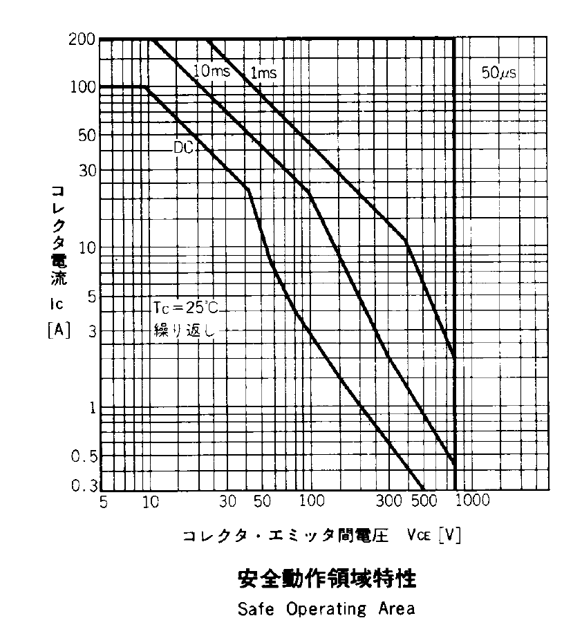
Bearing in mind that peak line voltage hits 170 – 180 V, 200 V looks like a convenient upper limit. Also, those limits apply at 25 °C case temperature and drop as the junctions warm up, although the datasheet remains mute as to the difference.
The circuit puts the following elements in series across the AC line:
- 5 A fast-blow fuse
- Normally open relay
- Full-wave rectifier block
- 120 VAC / 100 W universal motor
- ET227 NPN transistor
- 25 T x 2 parallel 24 AWG winding
After screwing around with Spice for a while, I can’t convince myself that the simulation means anything, but the general idea is that closing the relay at maximum line voltage (about 180 V) produces a staggeringly high current pulse through the series capacitances. A small amount of stray capacitance across the motor passes line voltage to the collector, the collector-base capacitance feeds it to the base, the transistor’s gain slams essentially unlimited current against line voltage, and the operating point squirts through the top of the SOA graph.
I made up a snubber from a 220 nF X capacitor and a 5.6 Ω resistor. That won’t have any effect on the spike, because the various stray / parasitic capacitors remain directly in series across the line, so the snubber looks like an open circuit. The snubber does damp the ringing after the spike vanishes, but that’s not the problem.
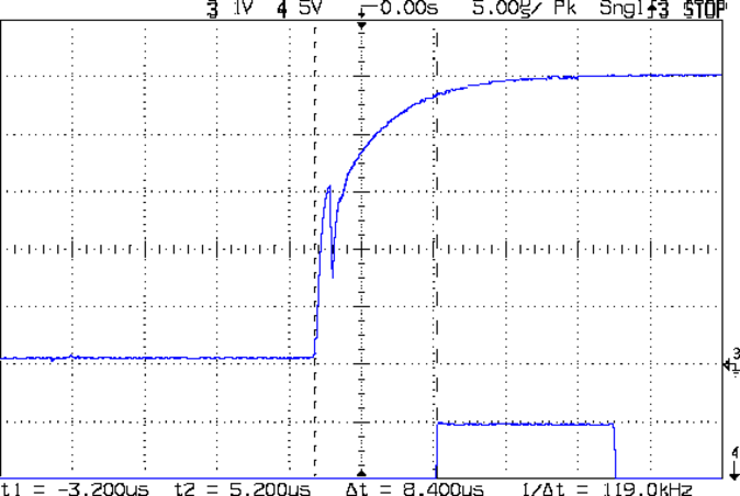
Some scope shots from ET227-C show the magnitude of the problem; it hasn’t blown yet, but obviously this can’t go on. Note the varying horizontal time scales and vertical current scales (all are at 10 mV/div, with the Tek probe providing the scaling).
At 50 mA/div, the two humps come from the (damped) ringing. This one doesn’t have much of a spike:

At 100 mA/div, I must have caught it at a higher point in the voltage waveform:

At 200 mA/div, this one looks seriously worse:

Now, agreed, a 1.6 A spike in a transistor rated for 200 A pulses doesn’t sound like much, but catching the spikes depends on random chance. If the collector voltage starts at 100 V, then that spike comes pretty close to the DC SOA limit; that’s not enough to kill the transistor, but it’s certainly suggestive.
Putting an NTC power thermistor in series would add some resistance to the circuit and reduce the magnitude of the spike, but they’re really intended for power supplies that draw a constant load, not a sewing machine that starts and stops all the time. If the motor runs for a while, then the thermistor will be hot for the next startup and the relay will close with relatively little resistance in the circuit.
More doodling seems in order.