Ed Nisley's Blog: Shop notes, electronics, firmware, machinery, 3D printing, laser cuttery, and curiosities. Contents: 100% human thinking, 0% AI slop.
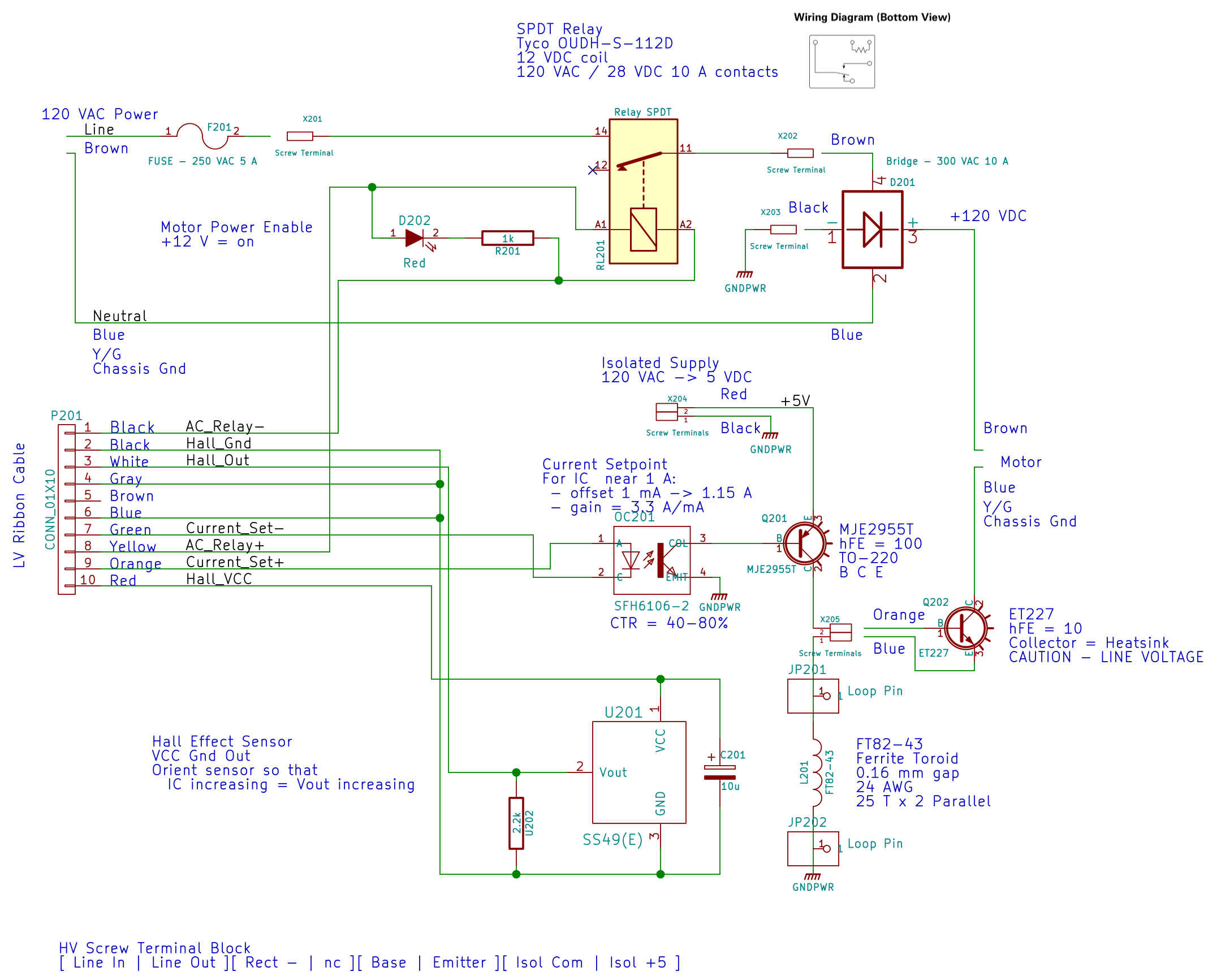
The relay at the top connects the AC hot line to the rest of the circuitry, with a feeble red LED to show when it’s live:
AC Power Interface
The driver lives on the Low Voltage Interface board:
LV Power Interface – AC Relay driver
The GX270’s front-panel hard drive LED now serves to indicate when the AC power goes live.
I’d originally intended to turn the AC on when the Arduino gains control, but after seeing those pictures, I think it’ll remain disabled unless there’s a call for motor motion.
The interlock switch closes when the case opens, grounding the transistor base and disconnecting the AC power.
Of course, you can cheat by simply unplugging the switch, so it’s not failsafe. If you want failsafe, you need a normally closed switch in series with the collector; that’s not what Dell used as a chassis intrusion switch. That’s my story and I’m sticking with it.
Although I plan to servo the motor speed to the pedal position, a quick open-loop test seems in order. The motor requires nigh onto half an amp before it can spin the sewing machine shaft, so this chunk of Arduino code scales-and-offsets ten bits of pedal position voltage into twelve bits of DAC output that produce a corresponding current limit for the motor winding:
Putting that in the Arduino’s main loop and holding the pedal down produces this pleasant result:
Current Sense Amp vs Tek – 200 mA-div
The current sense amp output in the top trace is scaled at 525 mA/V = 525 mA/div and the bottom trace is from the Tek current probe at 200 mA/div. Fiddling with the scope’s gain & offset exactly overlays the two traces and they remain overlaid through the full pedal travel, so the ferrite toroid isn’t saturating and the output remains nicely linear.
The flat tops in that picture show the ET227 transistor limiting the motor current to 600 mA, exactly the way it should.
Of course, the LM324 has a GBW = 1 MHz and, with a gain of three, a bandwidth of barely 300 kHz, so there’s a distinct lack of fuzz on that trace compared to the Tek probe’s 10 MHz bandwidth.
It’s easy to hold the sewing machine at a constant speed with a constant load, but touching the handwheel stalls the motor at a constant pedal position. Similarly, releasing the handwheel causes a runaway, unless I let up on the pedal fairly quickly.
Setting the Tek probe to 500 mA/div and triggering on a somewhat higher current while stomping on the pedal and grabbing the sewing machine’s handwheel shows the current increasing with the motor under heavier load:
Model 158 – Current sense vs Tek 500 mA-div
The current limit reaches just under 2 A, over on the right side, for both traces.
So the hardware works pretty much the way it should.
Given that the motor current amounts to maybe 3 A, absolute maximum, with a locked rotor, those skinny wires on the slit ferrite toroid won’t pose a problem:
HV Interface board – detail
I really like how that 3D printed armor worked out, even if I still haven’t poured any goop around the windings to lock them down; they’re held in by raw faith and friction.
The current sense circuitry appears along the bottom of the AC Power Interface schematic:
AC Power Interface
The differential amplifier lives on the Low Voltage Interface board, forming the clump of parts just in front of the LM324 op amp on the left:
Low Voltage Interface Board – detail
Which has the usual handful of components required to get anything done in the analog realm:
Current Sense Amp – schematic
The power supplies come directly from the ATX connector. I’m ignoring the whole decoupling issue, because the supplies have essentially no load (and it’s all DC, anyway).
The trim pot sets the offset voltage to bring the Hall effect sensors’s VCC/2 offset down close to zero; the 100 mV figure is nominal, not actual, but should be a bit over 0 V to allow for a wee bit o’ drift. This time around, I’ll measure and subtract the actual offset, rather than (try to) auto-zero it.
The voltage gain runs just under 3, set by 1% resistors from the heap. The overall gain works out to about 1.9 V/A or 525 mA/V, setting the high end at 5 V to a scant 2.6 A. Subject to actual calibration with more attention to detail, that’s close enough; we’re more interested in the around-an-amp range where the motor operates under nominal load.
The nose-to-tail Schottky diodes clamp the op amp output to avoid annoying the Arduino’s ADC input. It has protection circuitry, too, but there’s no point in stressing it.
Because the ET227 transistor operates at power line voltages through a full wave rectifier, the base drive circuit requires an optoisolator. The ET227 is a low-gain device with hFE < 10, so it takes about 100 mA of base drive to control an amp of motor current, soooo the optoisolator needs a current amplifier.
I used an MJE2955T PNP transistor, with the emitter powered from an isolated +5 V supply to let the optoisolator pull current from the base. You could use an NPN transistor as a Darlington amp, but wiring the collectors together means the driver dissipates way too much power; the PNP seemed all-around easier.
That circuitry sprawls across the middle of the schematic:
AC Power Interface
The ET227 base runs at about 900 mV, so the MJE2955 PNP transistor will dissipate half a watt and needs a little heatsink, seen over on the right (with the hulking ET227 heatsink at the edge):
HV Interface board – detail
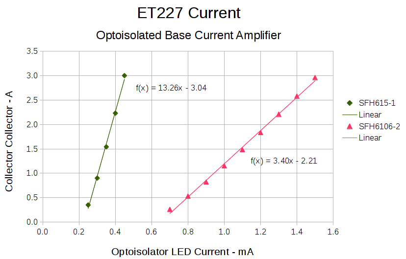
With all those parts safely secured, I ran some end-to-end current measurements from the optoisolator’s LED to the ET227’s collector current, with a safe 10 VDC applied to the collector:
ET227 – base drive – optoisolators
It’s worth noting that the two optoisolators have different pinouts. The DIP socket has wiring for both of ’em, so I could swap the two without rewiring the board. No, I didn’t notice that the first time around.
The curves are nicely linear above 250 mA, which is about what you’d expect for bipolar transistors driven from a current source. Below that, the current into the 13 Ω base-emitter resistor starts to overwhelm the actual base junction current and makes the curves all bendy. Given that the motor doesn’t start spinning the sewing machine with less than half an amp, that region doesn’t matter.
It’s also worth noting that the ET227 normally sees tens of amps (!) into the base terminal to control up to 200 A pulsed collector current with up to 1 kV collector voltage. That puppy loafs along here…
The ratio between the isolator gains doesn’t match the ratio between the spec sheet values, so maybe they’re mismarked or I (once again) have an outlier. In any event, there’s no point in getting too fussy, because the transistor gains depend strongly on temperature. I picked the lower-gain SFH6106-2 for more headroom, but it probably doesn’t make much difference.
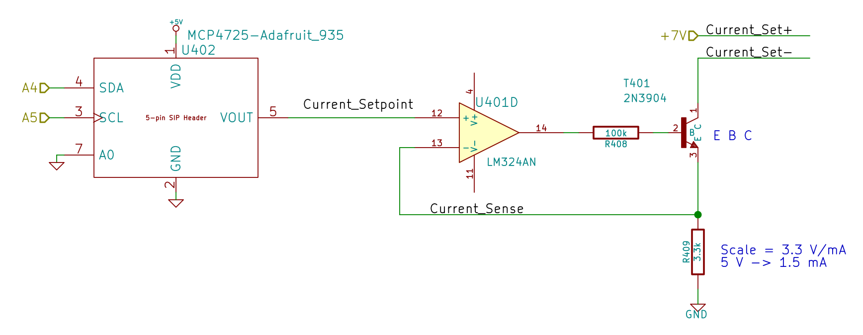
The voltage-to-current circuitry driving the optoisolator’s LED lives on the Low Voltage Interface board, with the MCP4725 DAC breakout board above the Arduino Pro Mini and the rest just beyond the LM324 op amp over on the left:
Low Voltage Interface Board – detail
There’s nothing much to it:
Current Control DAC and Driver – schematic
I finally broke down and got some of Adafruit’s nice MCP4725 I2C DAC breakout boards: 12 bits, rail-to-rail output, no PWM ripple. What’s not to like?
R409 scales the gain so that +5 V tops out around 1.5 mA, which should deliver a collector current around 3 A: far more than seems absolutely necessary. R408 lets the op amp develop some voltage while trickling a few dozen microamps into the 2N3904’s base; the hFE runs around 50, so the error due to base current amounts to maybe 2% and, remember, the final current depends on the temperature anyway.
Given that the GX270 case has a power pushbutton on the front panel, it seemed only reasonable to let it control the ATX power supply just like it used to. Most of the parts clumped in front of the panel’s ribbon cable handle that logic:
Low Voltage Interface Board – detail
The pushbutton on the far left parallels the front-panel button so I don’t have to reach around the box just to turn it on.
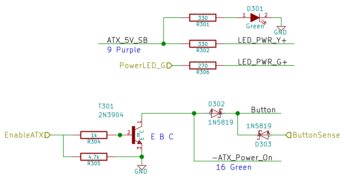
The schematic shows the relevant bits:
LV Power Interface – Power Button
The ATX +5 V Standby output remains turned on all the time, so I wired that to the power button’s yellow LED, to show that the plug is in the wall.
The pushbutton pulls the ATX Power_On line down, which turns on the supply outputs, which fires up the Arduino, which turns on the transistor, which holds the Power_On line down. D302 isolates the transistor from the button, so the code can sense the button’s on/off state with the power on. D303 isolates the Power_On line from the sense input to prevent the pullup on the Power_On line from back-powering the Arduino through its input protection diodes when the power is off.
The Arduino code starts by arranging the I/O states, turning the transistor on, pulsing the green power LED until until the button releases, then leaving the green LED on:
pinMode(PIN_PWR_G,OUTPUT);
digitalWrite(PIN_PWR_G,HIGH); // visible on front panel
pinMode(PIN_ENABLE_ATX,OUTPUT); // hold ATX power supply on
digitalWrite(PIN_ENABLE_ATX,HIGH);
pinMode(PIN_ENABLE_AC,OUTPUT); // turn on AC power
digitalWrite(PIN_ENABLE_AC,HIGH);
pinMode(PIN_BUTTON_SENSE,INPUT_PULLUP); // wait for power button release
while (LOW == digitalRead(PIN_BUTTON_SENSE)) {
delay(50);
TogglePin(PIN_PWR_G); // show we have control
}
digitalWrite(PIN_PWR_G,HIGH);
Every time around the main loop, this chunk of code checks the button input:
if (LOW == digitalRead(PIN_BUTTON_SENSE)) {
printf("Shutting down!\r\n");
digitalWrite(PIN_ENABLE_AC,LOW);
digitalWrite(PIN_ENABLE_ATX,LOW);
while(true) {
delay(20);
TogglePin(PIN_PWR_G); // show we have shut down
}
}
The never-ending loop blinks the green LED until the power goes down, which happens when the button releases. That terminates the loop with extreme prejudice., which is the difference between embedded programming and high-falutin’ Webbish stuff.
Commercial LED strip lights for sewing machines mount their cables with little stick-on anchors and cable ties. I wasn’t happy with the cable tie thing and finally figured this out:
Kenmore 158 – LED strip light cable clips
The clips have that size & shape because they fit exactly atop some pre-cut foam squares from the Tape Lookaside Buffer:
LED strip light cable clips
You can see the shape better in the solid model:
LED Cable Clips
The central bollard has a slight taper to retain the cable, the quarter-posts are straight, and they’re both twice the cable diameter tall. The clearance between the center and corner posts at the top matches the cable diameter, so there’s a bit of bending room at the bottom, and, with the cable bent around the center, it won’t fall out on its own.
The cute coaxial cable I’m misusing for the LED strips measures just shy of 2 mm, making these into little bitty things. The corner posts seem surprisingly strong, despite 3D printing’s reputation for crappy quality; I haven’t been able to break one off with more effort than seemed warranted.
The OpenSCAD source code:
// LED Cable Clips
// Ed Nisley - KE4ZNU - October 2014
//- Extrusion parameters must match reality!
ThreadThick = 0.20;
ThreadWidth = 0.40;
HoleWindage = 0.2; // extra clearance
Protrusion = 0.1; // make holes end cleanly
AlignPinOD = 1.70; // assembly alignment pins: filament dia
function IntegerMultiple(Size,Unit) = Unit * ceil(Size / Unit);
//----------------------
// Dimensions
Base = [12.0,12.0,IntegerMultiple(2.0,ThreadThick)]; // base over sticky square
CableOD = 2.0;
BendRadius = 3.0;
Bollard = [BendRadius,(sqrt(2)*Base[0]/2 - CableOD - BendRadius),2*CableOD];
B_BOT = 0;
B_TOP = 1;
B_LEN = 2;
NumSides = 5*4;
//----------------------
// Useful routines
module PolyCyl(Dia,Height,ForceSides=0) { // based on nophead's polyholes
Sides = (ForceSides != 0) ? ForceSides : (ceil(Dia) + 2);
FixDia = Dia / cos(180/Sides);
cylinder(r=(FixDia + HoleWindage)/2,
h=Height,
$fn=Sides);
}
module ShowPegGrid(Space = 10.0,Size = 1.0) {
RangeX = floor(100 / Space);
RangeY = floor(125 / Space);
for (x=[-RangeX:RangeX])
for (y=[-RangeY:RangeY])
translate([x*Space,y*Space,Size/2])
%cube(Size,center=true);
}
//----------------------
// Build it
ShowPegGrid();
intersection() {
translate([0,0,(Base[2] + Bollard[2])/2]) // overall XYZ outline
cube(Base + [0,0,Bollard[2]],center=true);
union() {
translate([0,0,Base[2]/2]) // oversize mount base
scale([2,2,1])
cube(Base,center=true);
for (i=[-1,1] , j=[-1,1]) { // corner bollards
translate([i*Base[0]/2,j*Base[1]/2,(Base[2] - Protrusion)])
rotate(180/NumSides)
cylinder(r=Bollard[B_BOT],h=(Bollard[B_LEN] + Protrusion),center=false,$fn=NumSides);
translate([0,0,(Base[2] - Protrusion)]) // center tapered bollard
cylinder(r1=Bollard[B_BOT],r2=Bollard[B_TOP],h=(Bollard[B_LEN] + Protrusion),center=false,$fn=NumSides);
}
}
}
Now that I think of it, maybe a round clip would look nicer. The central bollard would stay, but the circular outside rim could have three cutouts. When these fall off, I’ll give that a try.
They may be square and clunky, but they look much better than Gorilla Tape…