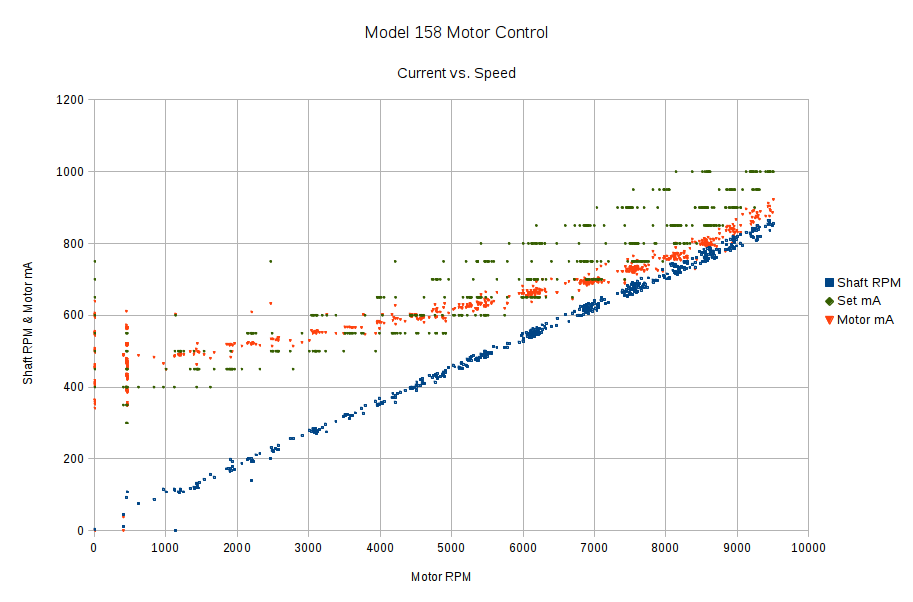
Now that the Arduino can set the current limiter, then measure the motor RPM, shaft RPM, and actual motor current, I can make plots like this:
The data comes from a routine that increments the setpoint current by 50 mA every five seconds, bouncing off 250 mA on the low end and 1 A on the high end, and writes the values to the serial port every half second. The actual current need not match the setpoint current, because it’s running open loop, and I haven’t done much in the way of calibration, so these represent interesting trends rather than dependable data points.
The eyeballometric slope down the middle of that blue smear comes out spot on 0.90, making the belt reduction 11.1 in good agreement with the results of those pulses.
The motor starts turning at 650 mA and will continue running down to maybe 500 mA, but with essentially zero low-end torque.
The horizontal range of green dots at each current setting shows that, as expected, the setpoint current has only a vague relation to the resulting motor speed: setting 800 mA will produce a speed between 5500 RPM and 9000 RPM, for sure. The actual motor current resulting from a given DAC output depends on the various transistor gains, all of which depend on temperature, which depends on how long the firmware has been running the motor at which speeds. Plenty of variation to go around.
The red points show that the actual motor current, as measured by the Hall effect sensor, generally lies below the green setpoint values, so better calibration is in order. Temperature effects turn accurate open-loop calibration into a fool’s errand, but we can do better than what you see there.
However, those red points do cluster much better, particularly between 6000 and 9000 RPM. You still can’t depend on the correlation, though, because the motor runs with a constant load here. In real life, the load will vary and so will the current required to maintain a given speed.
The green setpoints diverge from the red measurements at the high end, because the current limiter stops having much of an effect when the motor runs flat-out and sets its own current. After all, the original carbon-disk rheostat connected the line voltage directly across the motor, at which point the motor’s 100 W rating comes into play and limits the current to a nice sine wave with 1 A peaks.
All in all, it looks pretty good…
