Ed Nisley's Blog: Shop notes, electronics, firmware, machinery, 3D printing, laser cuttery, and curiosities. Contents: 100% human thinking, 0% AI slop.
Reducing the differential amp gain fits a higher current into the Arduino’s fixed 5 V ADC range:
Hall Sensor Differential Amp
Those are 1% resistors, chosen from the heap for being pretty close to what I needed. Given that it’s an LM324 op amp, we’re not talking instrumentation grade results here.
The same calibration run that produced the DAC plot gave these values:
Current Calibrate – ADC – 270k Hall 2.7k opto
The linear fit gives the actual current, as seen by the Tek probe, for a given ADC reading.
The trimpot controls the offset voltage at zero current; working backwards, ADC = 0 corresponds to 140 mV, a bit higher than the actual 90 mV. Close enough, at least for a linear fit to eyeballed data, sez I.
Working forward, the maximum ADC value of 1023 corresponds to 4 A, which should suffice.
Although small power diodes make fine flyback diodes for relays, the motor can draw several amps during the startup pulse, which will be a bit out of spec for the usual 1N4007-class diodes. Pressing an old 5 A / 200 V stud diode into service produces the ungainly black-and-blue lump eating the end of the green wire:
Motor flyback diode – installed
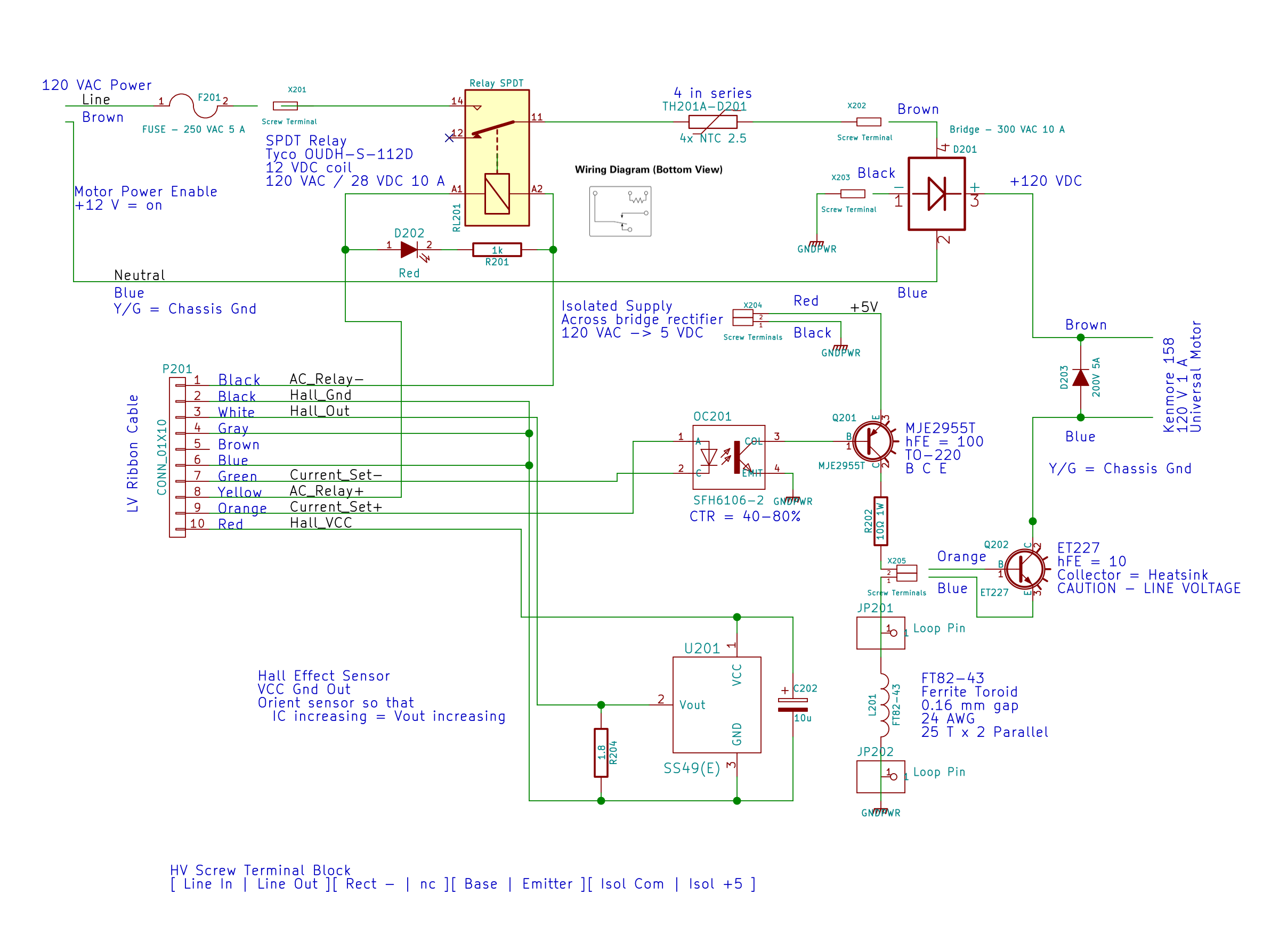
For completeness, here’s the entire AC line interface part of the schematic:
AC Power Interface
The diode’s 200 V limit should suffice, even for cold starts at high line peaks, but, when you build this with new parts, get something rated a bit higher, OK?
A Circuit Cellar reader sent me a lengthy note describing his approach to slow-motion AC motor drives, designed for an already ancient truck mounted radar antenna back in 1972-ish, that prompted me to try it his way.
The general idea is to pulse the motor at full current for half a power line cycle with an SCR (rather than a triac) at a variable pulse repetition rate: the high current pulse ensures that the motor will start turning and the variable repetition frequency determines the average speed. As he puts it, the motor will give off a distinct tick at very low speeds and the maximum speed will depend on how the motor reacts to half-wave drive.
Note that this is not the chopped-current approach to speed control: the SCR always begins conducting at the first positive-going 0 V crossing after the command and continues until the motor current drops to zero. There are no sharp edges generating high-pitched acoustic noise and EMI: silence is golden.
The existing speed control circuitry limits the peak current and assumes that the motor trundles along more-or-less steadily. That won’t be the case when it’s coasting between discontinuous current pulses.
When I first looked at running the motor on DC, these measurements showed the expected relationship:
Kenmore Model 158 AC Motor on DC – Loaded and Unloaded RPM vs Voltage
Eyeballometrically, the slowest useful speed will be 2 stitch/s = 120 shaft RPM = 1300 motor RPM. At that speed, under minimal load, the motor runs on about 20 V and draws 550 mA. At that current, the 40 Ω winding drops 22 V, which we’ll define as “about 20 V” for this discussion, so the back EMF amounts to pretty nearly zilch.
That’s what you’d expect for the fraction of a second while the motor comes up to full speed, but in this case it never reaches full speed, so the motor current during the pulses will be limited only by the winding resistance. At the 200 V peak I’ve been using for the high-line condition, that’s about 5 A peak, although I’d expect 4 A to be more typical.
So, in order to make this work:
the optocoupler driving the base needs more current
the differential amp from the Hall effect sensor needs less gain
Given the ease with which I’ve pushed the hulking ET227 transistor out of its SOA, the motor definitely needs a flyback diode to direct the winding current away from the collector as the transistor shut off at the end of the pulse. Because it’s running from full-wave rectified AC, the winding current never drops to zero: there will definitely be enough current to wreck the transistor.
The firmware needs reworking to produce discrete pulses at a regular pace, rather than slowly adjusting the current over time, but that’s a simple matter of software…
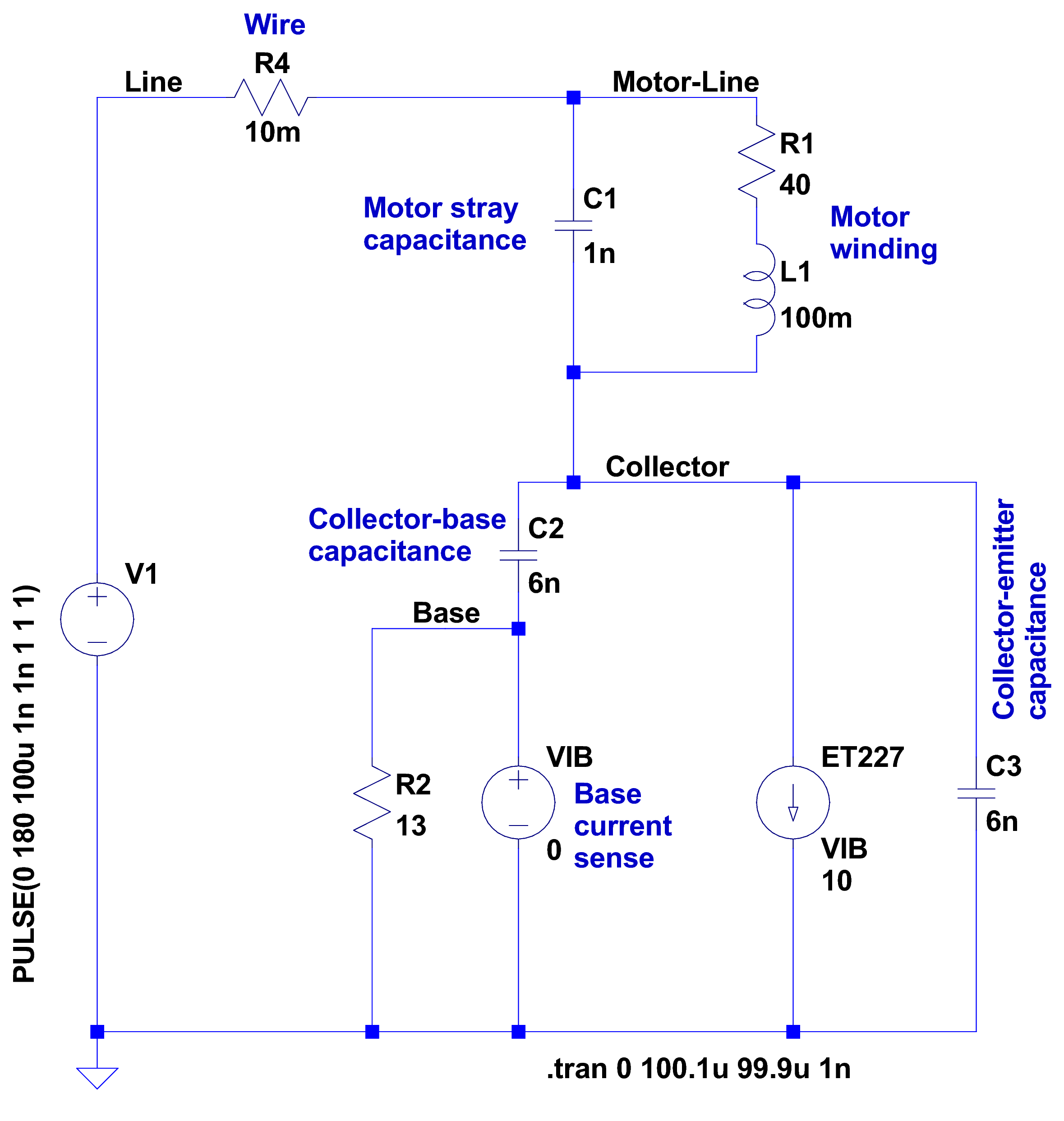
After having blown two ET227 transistors, I fiddled with some SPICE models to explore the ahem problem space. This seems to be the simplest model with all the relevant details:
Motor Transient – no NTC – schematic
A step change in the voltage source simulates the relay clicking closed with the AC line at a peak. R4 might resemble the total wiring resistance, but is more of a placeholder.
I measured 1 nF from each motor wire to the motor shell, so I assume a similar value from wire to wire across the winding. I can’t measure that, because, as far as my capacitance meters are concerned, the 40 Ω motor winding looks exactly like a resistor. R1 and L1 model the winding / commutator, but on the time scale we’re interested in, that branch remains an open circuit.
There’s no transistor model even faintly resembling a hulking ET227, so a current controlled current source must suffice. The 0 V VIB “source” in the base lead measures the base current for the CCCS labeled ET227, which applies a gain of 10 to that value and pulls that current from the collector node. R2 is the internal base-emitter resistor built into the ET227.
C2 is the 6 nF (!) collector-base capacitance I measured at zero DC bias on a good ET227. That’s much more than you’ll find on any normal transistor and I’m basically assuming it’s vaguely related to the Miller capacitance of small-signal fame. C3 is a similar collector-emitter capacitor; I can’t tell what’s going on under the hood without a whole lot of measurement equipment I don’t have.
So, without further ado:
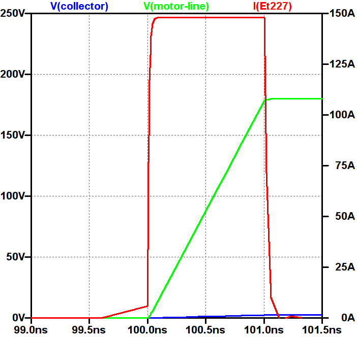
Simple Transient Model – current pulse
Whenever you see a simulation result like that, grab your hat in both hands and hunker down; the breeze from the handwaving will blow you right off your seat.
The key unknown: the rise time of the voltage step as the relay contacts snap closed. Old-school mercury-wetted relay contacts have rise times in the low tens of picoseconds. Figuring dry high-power contacts might be 100 times slower gives a 1 ns rise time that I can’t defend very strongly; it seems to be in the right ballpark. The green trace shows the input voltage ramping to 180 V in 1 ns, which is pretty much an irresistible force.
The motor shunt capacitance forms a voltage divider with the parallel base and collector capacitors, so the collector voltage shouldn’t exceed 180 * (1/(1+3)) = 45 V. In fact, the blue trace shows the collector voltage remains very low, on the order of 10 V, during the whole pulse.
The red trace shows the collector current hitting 150 A during the entire input ramp, which is exactly what you’d expect from the basic capacitor equation: I = C dv/dt. The current depends entirely on the absurdly fast 180 V / 1 ns rate: if the relay rise time is actually smaller, the current gets absurdly higher.
The ET227 datasheet remains mute on things like junction capacitance, damage done by nanosecond-scale high-current pulses, and the like.
Absolutely none of those numbers have even one significant figure of accuracy, but I think the overall conclusion that I’m blowing junctions based on transient startup currents through the collector holds water.
Adding four of those NTC power thermistors seems in order. This picture also shows the snubber hanging from the back of the ET227, but I eventually took that off because the simulations show it’s not doing anything useful and it does resonate with the 120 Hz halfwave supply:
HV Interface – snubber and thermistors
The thermistors get comfortably warm after a few minutes and settle out around 1 Ω apiece. Adding 4 Ω to the simulation reduces the current to 30 A during a 1 ns ramp, which number obviously depends on all the assumptions mentioned above.
I’ve been running it like that for a few hours of start-stop operation and the ET227 lives on, so maybe I can declare victory.
Another nine hours of printing produced a second 9×13 link chain mail armor sheet that simply begged to be joined with the first. Snipping a connecting link on one sheet and attempting to thread it through the armor button on the other didn’t work nearly as well as I expected, because the pillars on the open links don’t quite pass through the slot in the side of the armor button links:
Chain Mail Armor – 4 sided
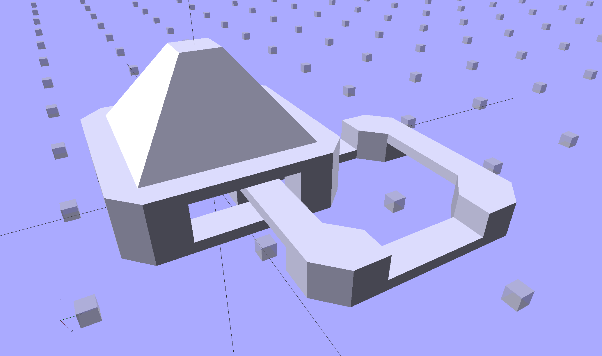
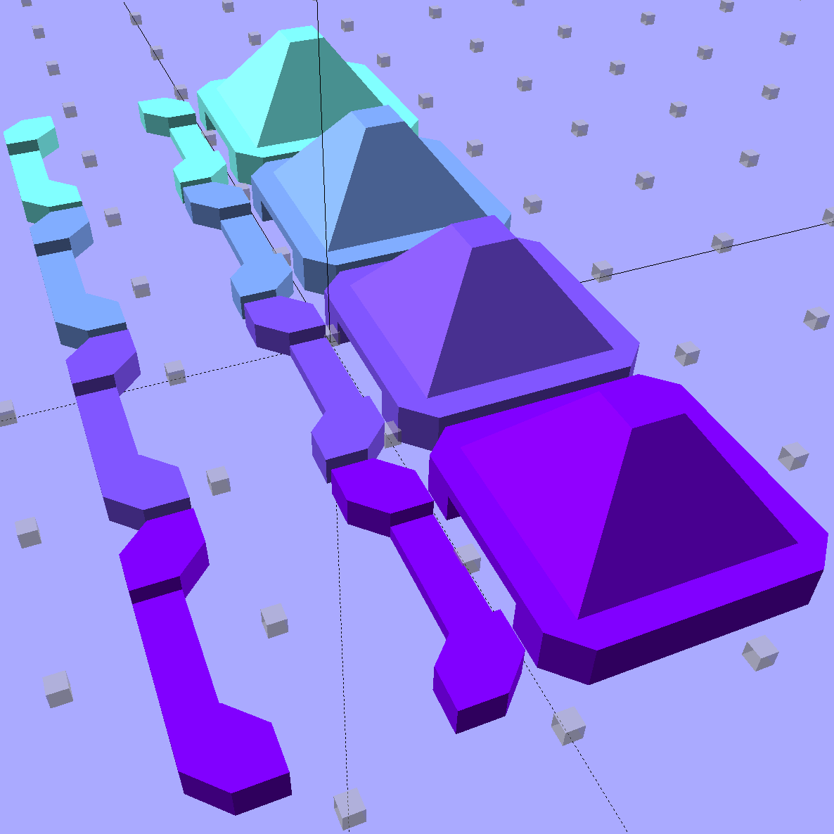
So I summoned joiner links from the digital deep:
Chain Mail Armor – Sheet Joiners
Those are standard armor button links, split at the cross bar level, then laid out along the Y axis. The cap bridges across the link just as it does on the chain mail sheets, so, when they’re glued back together, the result should be exactly like a solid link. There’s no room for alignment pins and, frankly, I wouldn’t fiddle with two dozen filament snippets anyway.
The OpenSCAD code below produces joiners that work for the square arrangement, not the diamond, but that’s in the nature of fine tuning.
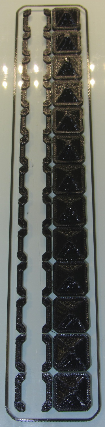
When I saw them pasted to the platform, just like the model:
Chain Mail Armor – joiners on platform
It occurred to me that I could pop the caps off, then lay the sheets in position, aligned on the underlying joiner half-links. Here’s the first sheet over the left set of bars:
Chain Mail Armor – sheet and joiners on platform
Then glue the armor caps in place:
Chain Mail Armor – joiner with solvent glue
Four dots of IPS #4 solvent glue, dispensed from a fine copper tube serving as a pipette, wet the four pillars of the joiner’s two bottom bars. I dotted each pillar to begin softening the PLA, paused for a breath, wet them again to leave enough solvent to bite into the bottom of the armor cap, pressed the cap in place, tweaked the alignment with tweezers, then pressed downward for maybe five seconds. Although the joiner link has no inherent alignment features, there’s also not much room to slide around and it worked surprisingly well.
Repeat that trick dozen times and you’re done. The aggravation scales as the square root of the overall sheet size, so it’s not as awful as assembling every single link, but it’s definitely a task for the low-caffeine part of the day.
One bottom bar came loose when I showed the result at the MHVLUG meeting, but the bar reappeared and I glued it again easily enough. I’ve now printed several spare joiners, Just In Case.
The bottom bars aren’t firmly affixed to the platform after it cools and they dislodge fairly easily: that’s how I get larger models off: let everything cool, then simply lift the plastic off. If I were joining sheets on a regular basis, I’d conjure a fixture to hold the sheets and joiner caps in position, probably with the sheets upside down, then glue the bars atop the inverted caps. That could get messy.
Perhaps a special holder to capture the bars in the proper alignment, maybe with pins matching the square openings at the corners, would help?
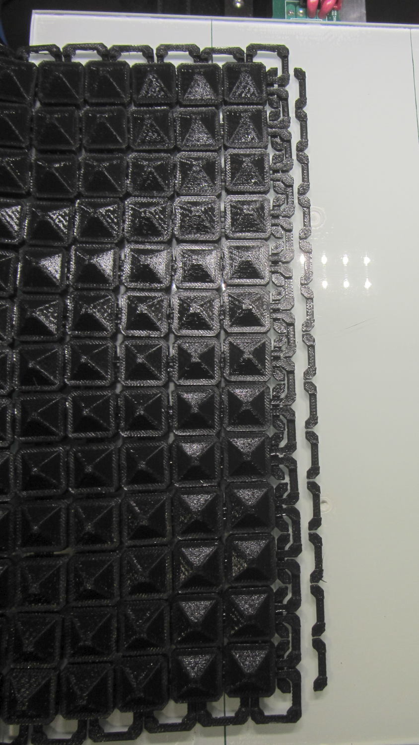
This is a trial fit before gluing that’s visually indistinguishable from the final product:
Chain Mail Armor – joined sheets on platform
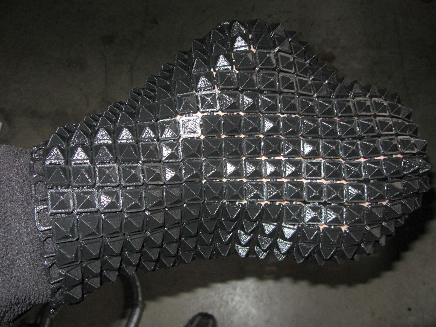
It’s not actually fabric, but it’s sufficiently bendy to cover a hand:
Chain Mail Armor – joined sheet draped on hand
The thing just cries out to be fondled…
There’s a quarter kilogram of plastic in that 8×12 inch = 200×310 mm sheet that almost used up the last of the black PLA spool.
Remember: you must tweak the OpenSCAD code to match your extruder settings, export a suitable STL file, get really compulsive about platform alignment, use hairspray / glue stick to boost platform adhesion, and have no qualms about an all-day print run. You can’t just slice a random STL file produced for a different printer, because the link dimensions come directly from the printer’s capabilities: one size does not fit all.
The OpenSCAD source code [Update: This is the refactored version.]:
// Chain Mail Armor Buttons
// Ed Nisley KE4ZNU - December 2014

Layout = "Build";			// Link Button LB Joiner Joiners Build

//-------
//- Extrusion parameters must match reality!
//  Print with 1 shell and 2+2 solid layers

ThreadThick = 0.20;
ThreadWidth = 0.40;

HoleWindage = 0.2;

Protrusion = 0.1*ThreadThick;			// make holes end cleanly

function IntegerMultiple(Size,Unit) = Unit * ceil(Size / Unit);

//-------
// Dimensions

//- Set maximum sheet size

SheetSizeX = 50;	// 170 for full sheet on M2
SheetSizeY = 60;	// 230

//- Diamond or rectangular sheet?

Diamond = false;					// true = rotate 45 degrees, false = 0 degrees for square

BendAround = "X";					// X or Y = maximum flexibility *around* designated axis

Cap = true;										// true = build bridge layers over links

Armor = true && Cap;							// true = build armor button atop (required) cap
ArmorThick = IntegerMultiple(6,ThreadThick);	// height above cap surface

// Link bar sizes

BarWidth = 6 * ThreadWidth;
BarThick = 4 * ThreadThick;

BarClearance = 5*ThreadThick;		// vertical clearance above & below bars

//-- Compute link sizes from those values

// Absolute minimum base link: bar width + corner angle + build clearance around bars
//  rounded up to multiple of thread width to ensure clean filling
BaseSide = IntegerMultiple((4*BarWidth + 2*BarWidth/sqrt(2) + 3*(2*ThreadWidth)),ThreadWidth);

BaseHeight = 2*BarThick + BarClearance;           // both bars + clearance

echo(str("BaseSide: ",BaseSide," BaseHeight: ",BaseHeight));
echo(str(" Base elements: ",4*BarWidth,", ",2*BarWidth/sqrt(2),", ",3*(2*ThreadWidth)));
echo(str(" total: ",(4*BarWidth + 2*BarWidth/sqrt(2) + 3*(2*ThreadWidth))));

BaseOutDiagonal = BaseSide*sqrt(2) - BarWidth;
BaseInDiagonal = BaseSide*sqrt(2) - 2*(BarWidth/2 + BarWidth*sqrt(2));

echo(str("Outside diagonal: ",BaseOutDiagonal));

//- On-center distance measured along coordinate axis
//   the links are interlaced, so this is half of what you think it should be...

LinkOC = BaseSide/2 + ThreadWidth;

LinkSpacing = Diamond ? (sqrt(2)*LinkOC) : LinkOC;
echo(str("Base spacing: ",LinkSpacing));

//- Compute how many links fit in sheet

MinLinksX = ceil((SheetSizeX - (Diamond ? BaseOutDiagonal : BaseSide)) / LinkSpacing);
MinLinksY = ceil((SheetSizeY - (Diamond ? BaseOutDiagonal : BaseSide)) / LinkSpacing);
echo(str("MinLinks X: ",MinLinksX," Y: ",MinLinksY));

NumLinksX = ((0 == (MinLinksX % 2)) && !Diamond) ? MinLinksX + 1 : MinLinksX;
NumLinksY = ((0 == (MinLinksY % 2) && !Diamond)) ? MinLinksY + 1 : MinLinksY;
echo(str("Links X: ",NumLinksX," Y: ",NumLinksY));

//- Armor button base

CapThick = 4 * ThreadThick;						// at least 3 layers for solid bridging

ButtonHeight = BaseHeight + BarClearance + CapThick;
echo(str("ButtonHeight: ",ButtonHeight));

//- Armor ornament size & shape
//		Fine-tune OD & ID to suit the number of sides...

ArmorSides = 4;
ArmorAngle = true ? 180/ArmorSides : 0;			// true -> rotate half a side for best alignment

TotalHeight = ButtonHeight + ArmorThick;
echo(str("Overall Armor Height: ",TotalHeight));

ArmorOD = 1.1 * BaseSide;						// tune for best base fit
ArmorID = 10 * ThreadWidth;						// make the tip blunt & strong

//-------

module ShowPegGrid(Space = 10.0,Size = 1.0) {

  RangeX = floor(95 / Space);
  RangeY = floor(125 / Space);

	for (x=[-RangeX:RangeX])
	  for (y=[-RangeY:RangeY])
		translate([x*Space,y*Space,Size/2])
		  %cube(Size,center=true);

}

//-------
// Create link with armor button as needed

module Link(Topping = false) {

LinkHeight = (Topping && Cap) ? ButtonHeight : BaseHeight;

render(convexity=3)
	rotate((BendAround == "X") ? 90 : 0)
	rotate(Diamond ? 45 : 0)
		union() {
			difference() {
				translate([0,0,LinkHeight/2])	// outside shape
					intersection() {
						cube([BaseSide,BaseSide,LinkHeight],center=true);
						rotate(45)
							cube([BaseOutDiagonal,BaseOutDiagonal,LinkHeight],center=true);
					}
				translate([0,0,(BaseHeight + BarClearance - Protrusion)/2])
					intersection() {		// inside shape
						cube([(BaseSide - 2*BarWidth),
								(BaseSide - 2*BarWidth),
								(BaseHeight + BarClearance + Protrusion)],
								center=true);
						rotate(45)
							cube([BaseInDiagonal,
									BaseInDiagonal,
									(BaseHeight + BarClearance + Protrusion)],
									center=true);
				}

				translate([0,0,((BarThick + 2*BarClearance)/2 + BarThick)])		// openings for bars
					cube([(BaseSide - 2*BarWidth - 2*BarWidth/sqrt(2)),
						(2*BaseSide),
						BarThick + 2*BarClearance],
						center=true);

				translate([0,0,(BaseHeight/2 - BarThick)])
					cube([(2*BaseSide),
						(BaseSide - 2*BarWidth - 2*BarWidth/sqrt(2)),
						BaseHeight],
						center=true);

			}

			if (Topping && Armor)
				translate([0,0,(ButtonHeight - Protrusion)])		// sink slightly into the cap
					rotate(ArmorAngle)
					cylinder(d1=ArmorOD,
							 d2=ArmorID,
							 h=(ArmorThick + Protrusion),
							 $fn=ArmorSides);
		}
}

//-------
// Create split buttons to join sheets

module Joiner() {

	translate([-LinkSpacing,0,0])
		difference() {
			Link(false);
			translate([0,0,BarThick + BarClearance + TotalHeight/2 - Protrusion])
				cube([2*LinkSpacing,2*LinkSpacing,TotalHeight],center=true);
		}

	translate([LinkSpacing,0,0])
		intersection() {
			translate([0,0,-(BarThick + BarClearance)])
				Link(true);
			translate([0,0,TotalHeight/2])
				cube([2*LinkSpacing,2*LinkSpacing,TotalHeight],center=true);
		}

}

//-------
// Build it!

ShowPegGrid();

if (Layout == "Link") {
	Link(false);
}

if (Layout == "Button") {
	Link(true);
}

if (Layout == "LB") {
	Link(true);
	translate([LinkSpacing,LinkSpacing,0])
		Link(false);
}

if (Layout == "Build")
	for (ix = [0:(NumLinksX - 1)],
		 iy = [0:(NumLinksY - 1)]) {
			x = (ix - (NumLinksX - 1)/2)*LinkSpacing;
			y = (iy - (NumLinksY - 1)/2)*LinkSpacing;
			translate([x,y,0])
			color([(ix/(NumLinksX - 1)),(iy/(NumLinksY - 1)),1.0])
				if (Diamond)
					Link((ix + iy) % 2);					// armor at odd,odd & even,even points
				else
					if ((iy % 2) && (ix % 2))				// armor at odd,odd points
                        Link(true);
					else if (!(iy % 2) && !(ix % 2))		// connectors at even,even points
						Link(false);
	}

if (Layout == "Joiner")
	Joiner();

if (Layout == "Joiners") {
	NumJoiners = max(MinLinksX,MinLinksY)/2;
	for (iy = [0:(NumJoiners - 1)]) {
		y = (iy - (NumJoiners - 1)/2)*2*LinkSpacing + LinkSpacing/2;
		translate([0,y,0])
			color([0.5,(iy/(NumJoiners - 1)),1.0])
				Joiner();
	}
}
As a reward for reading all the way to the bottom, some further thoughts:
A mask array could control what type of link goes where, which cap style goes on each armor button, and whether to print the link at all. That way, you could produce customized armor buttons in non-rectangular (albeit coarsely pixelized) fabric sheets.
You could produce an armor sheet sporting cubic caps, then intersect the whole sheet with a model built from a height-map image to spread a picture across the sheet. The complexity of that model would probably tie OpenSCAD in knots, but perhaps an external program could intersect two properly aligned STL / AMF files.
The bars could be a thread or two thinner, shaving a few millimeters off the basic link. The printer’s ability to bridge the link to form the flying bars and cap limits making the links much larger.
From a surplus batch, with no provenance, measuring the resistance with current increasing (upper = squares) and then decreasing (lower = diamonds):
NTC 2.5 Resistance vs Current
The resistance at a given current need not lie between those bounds, because it depends strongly on the thermistor’s temperature (duh), which depends on heat loss to the surroundings.
With that in mind, 1 or 2 Ω looks like the right ballpark for these gadgets. Figure around half a watt each at 600 mA; string three in series to get 9 Ω during a cold start and 3 Ω for warm starts. It’s not clear that would solve the transistor killing spike, but it’s a thought.
Compared to the SCK055 NTC thermistor, they have about the same resistance at the same current, despite starting at half the initial cold resistance. I think that’s because they’re somewhat larger and thus run cooler at a given current.
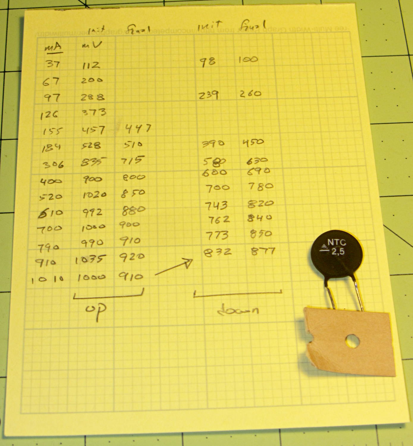
The original data and a portrait of the thermistor:
NTC 2.5 Power Thermistor – measurements
Anybody recognize the logo? The symbol in the striped triangle is S+M, if that helps.
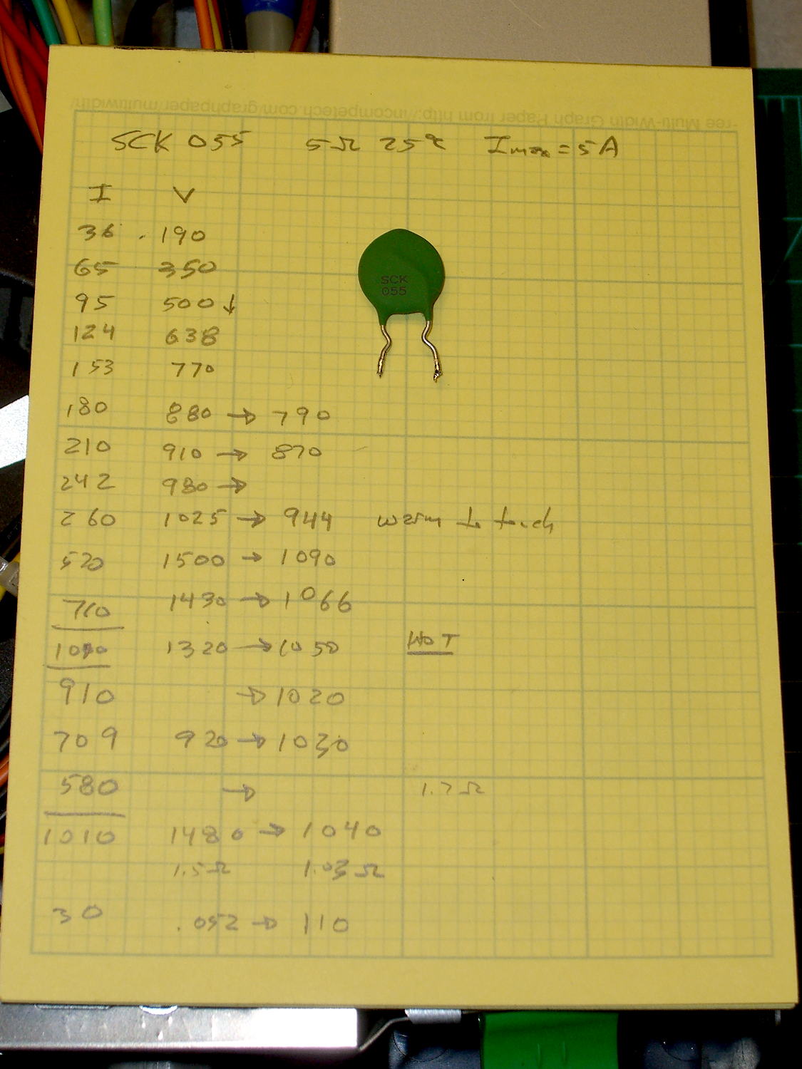
While pondering the dead ET227 transistors, I dug an inrush current limiter (a.k.a. NTC power thermistor) out of the heap and made some measurements:
SCK055 NTC Power Thermistor – measurements
That’s from a bench power supply attached to a meter and the limiter with clip leads, which was entirely too messy for a picture.
Turning those numbers into a spreadsheet to calculate the resistances:
SCK 055 NTC Power Thermistor
5 Ω @ 25 °C
Imax = 5 A
Time constant on the order of 90 seconds
Current mA
Initial mV
Final mV
Initial Ω
Final Ω
36
190
5.3
65
350
5.4
95
500
5.3
124
638
5.1
153
770
5.0
180
880
790
4.9
4.4
210
910
870
4.3
4.1
242
980
4.0
260
1025
944
3.9
3.6
520
1500
1090
2.9
2.1
710
1430
1066
2.0
1.5
1010
1320
1050
1.3
1.0
910
1020
1.1
709
920
1030
1.3
1.5
1010
1480
1040
1.5
1.0
30
52
110
1.7
3.7
The data sheet recommends a minimum current above 30% of the maximum, which would be 1.5 A. That’s above the motor’s 1 A operating current, let alone the low-speed current limited conditions, but in this situation that just means the resistance will remain around 1 to 2 Ω with the motor chugging along.
If I had more of ’em, I could put them in series to build up the resistance, but it’s not clear why that would be better than, say, a 6 Ω aluminum-heatsink resistor dissipating a few watts.