Ed Nisley's Blog: Shop notes, electronics, firmware, machinery, 3D printing, laser cuttery, and curiosities. Contents: 100% human thinking, 0% AI slop.
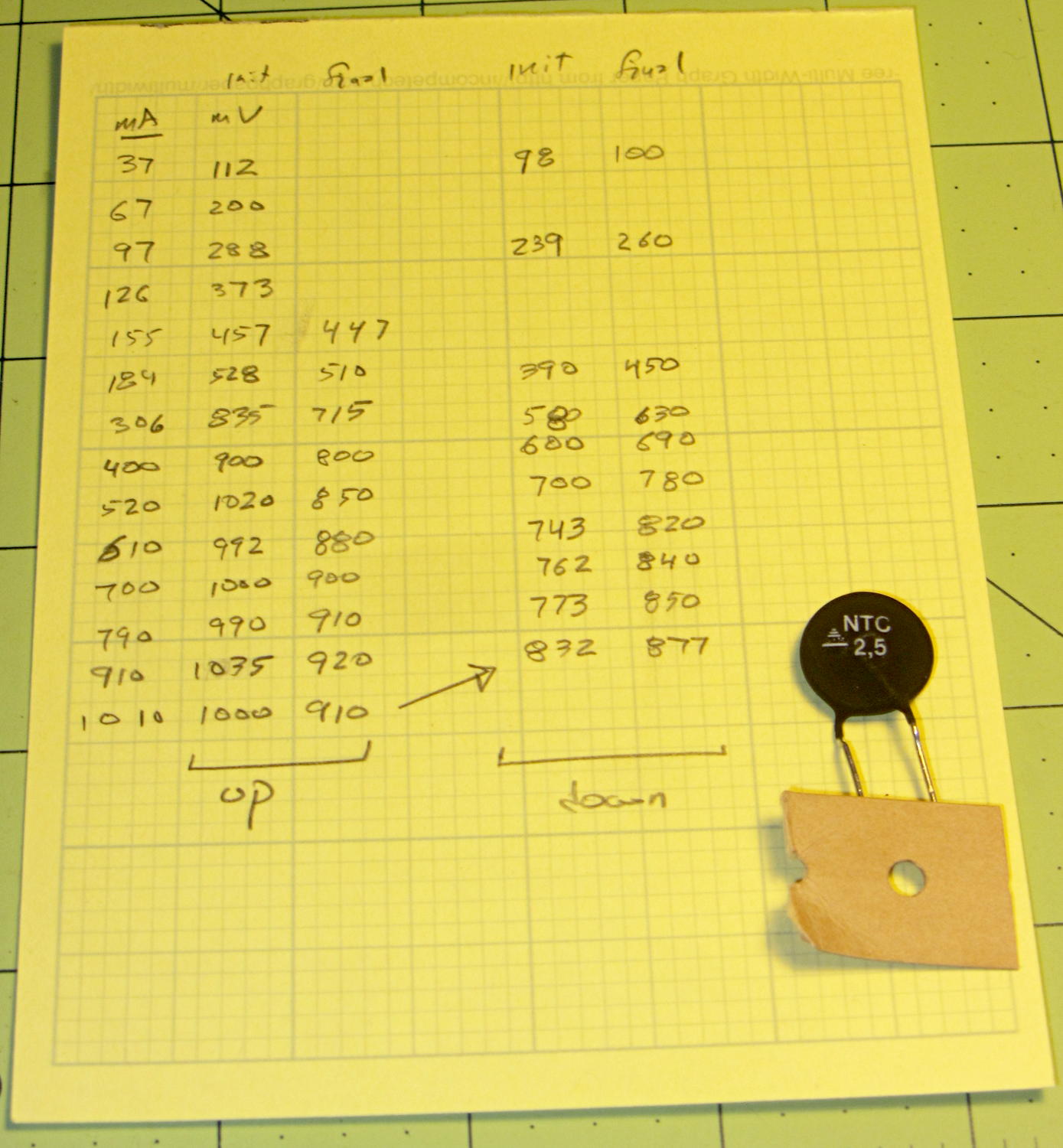
From a surplus batch, with no provenance, measuring the resistance with current increasing (upper = squares) and then decreasing (lower = diamonds):
NTC 2.5 Resistance vs Current
The resistance at a given current need not lie between those bounds, because it depends strongly on the thermistor’s temperature (duh), which depends on heat loss to the surroundings.
With that in mind, 1 or 2 Ω looks like the right ballpark for these gadgets. Figure around half a watt each at 600 mA; string three in series to get 9 Ω during a cold start and 3 Ω for warm starts. It’s not clear that would solve the transistor killing spike, but it’s a thought.
Compared to the SCK055 NTC thermistor, they have about the same resistance at the same current, despite starting at half the initial cold resistance. I think that’s because they’re somewhat larger and thus run cooler at a given current.
The original data and a portrait of the thermistor:
NTC 2.5 Power Thermistor – measurements
Anybody recognize the logo? The symbol in the striped triangle is S+M, if that helps.
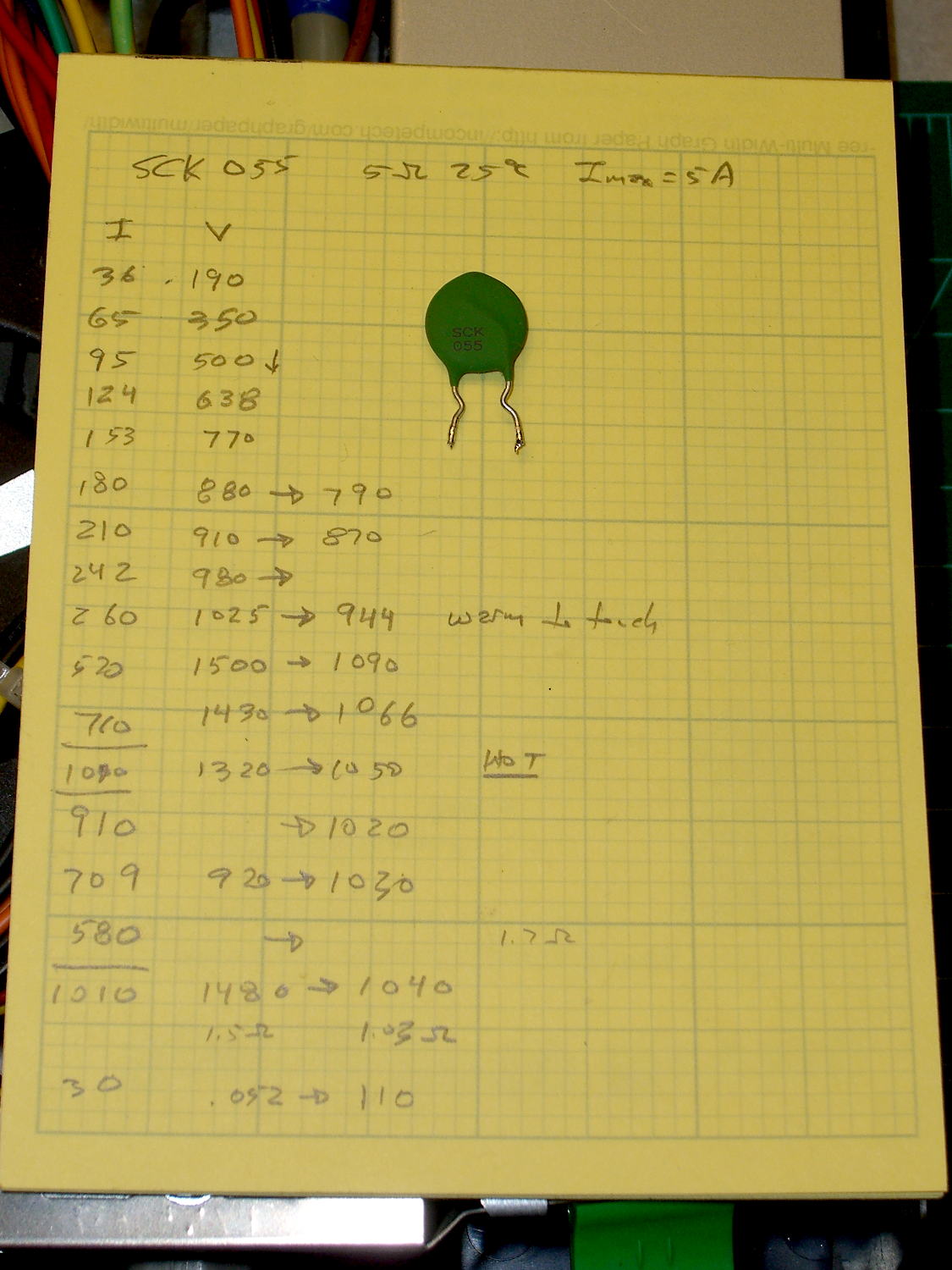
While pondering the dead ET227 transistors, I dug an inrush current limiter (a.k.a. NTC power thermistor) out of the heap and made some measurements:
SCK055 NTC Power Thermistor – measurements
That’s from a bench power supply attached to a meter and the limiter with clip leads, which was entirely too messy for a picture.
Turning those numbers into a spreadsheet to calculate the resistances:
SCK 055 NTC Power Thermistor
5 Ω @ 25 °C
Imax = 5 A
Time constant on the order of 90 seconds
Current mA
Initial mV
Final mV
Initial Ω
Final Ω
36
190
5.3
65
350
5.4
95
500
5.3
124
638
5.1
153
770
5.0
180
880
790
4.9
4.4
210
910
870
4.3
4.1
242
980
4.0
260
1025
944
3.9
3.6
520
1500
1090
2.9
2.1
710
1430
1066
2.0
1.5
1010
1320
1050
1.3
1.0
910
1020
1.1
709
920
1030
1.3
1.5
1010
1480
1040
1.5
1.0
30
52
110
1.7
3.7
The data sheet recommends a minimum current above 30% of the maximum, which would be 1.5 A. That’s above the motor’s 1 A operating current, let alone the low-speed current limited conditions, but in this situation that just means the resistance will remain around 1 to 2 Ω with the motor chugging along.
If I had more of ’em, I could put them in series to build up the resistance, but it’s not clear why that would be better than, say, a 6 Ω aluminum-heatsink resistor dissipating a few watts.
The ET227 transistor (labeled A from the DC gain tests) I’d been using, ever since the very beginning, failed with a collector-to-emitter short when I started it for a data taking run. In most circuits, that would be a catastrophic failure accompanied by arcs & sparks, but the Kenmore 158 simply started running at full speed and ignored my increasingly desperate attempts to regain control.
OK, those transistors date back to the 1980s (or maybe even earlier), so maybe It Was Time.
I swapped in ET227-B, buttoned everything up, and continued taking data.
Two days later, ET227-B failed with a collector-to-emitter short when it turned on.
Once is happenstance. Twice is coincidence. A third time means I missed the cluetrain.
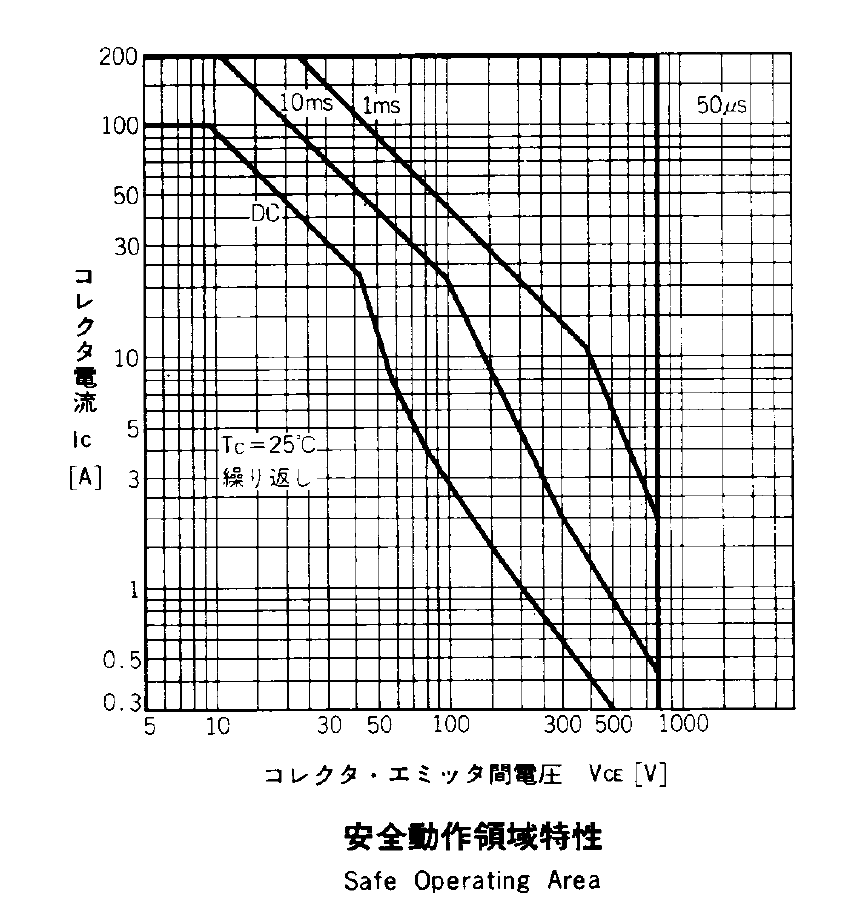
Although the ET227 can switch 1 kV and 100 A, the Safe Operating Area plot shows that the DC limit passes through 1 A at 200 V:
ET227 – Safe Operating Area
Bearing in mind that peak line voltage hits 170 – 180 V, 200 V looks like a convenient upper limit. Also, those limits apply at 25 °C case temperature and drop as the junctions warm up, although the datasheet remains mute as to the difference.
The circuit puts the following elements in series across the AC line:
5 A fast-blow fuse
Normally open relay
Full-wave rectifier block
120 VAC / 100 W universal motor
ET227 NPN transistor
25 T x 2 parallel 24 AWG winding
After screwing around with Spice for a while, I can’t convince myself that the simulation means anything, but the general idea is that closing the relay at maximum line voltage (about 180 V) produces a staggeringly high current pulse through the series capacitances. A small amount of stray capacitance across the motor passes line voltage to the collector, the collector-base capacitance feeds it to the base, the transistor’s gain slams essentially unlimited current against line voltage, and the operating point squirts through the top of the SOA graph.
I made up a snubber from a 220 nF X capacitor and a 5.6 Ω resistor. That won’t have any effect on the spike, because the various stray / parasitic capacitors remain directly in series across the line, so the snubber looks like an open circuit. The snubber does damp the ringing after the spike vanishes, but that’s not the problem.
Some scope shots from ET227-C show the magnitude of the problem; it hasn’t blown yet, but obviously this can’t go on. Note the varying horizontal time scales and vertical current scales (all are at 10 mV/div, with the Tek probe providing the scaling).
At 50 mA/div, the two humps come from the (damped) ringing. This one doesn’t have much of a spike:
Snubbed power on transient – ET227C 50 mA-div
At 100 mA/div, I must have caught it at a higher point in the voltage waveform:
Now, agreed, a 1.6 A spike in a transistor rated for 200 A pulses doesn’t sound like much, but catching the spikes depends on random chance. If the collector voltage starts at 100 V, then that spike comes pretty close to the DC SOA limit; that’s not enough to kill the transistor, but it’s certainly suggestive.
Putting an NTC power thermistor in series would add some resistance to the circuit and reduce the magnitude of the spike, but they’re really intended for power supplies that draw a constant load, not a sewing machine that starts and stops all the time. If the motor runs for a while, then the thermistor will be hot for the next startup and the relay will close with relatively little resistance in the circuit.
Plotting the motor RPM every 500 ms while increasing the nominal current by 50 mA per step from 550 mA:
Motor RPM vs Current Steps – Accelerating
And then downward from 950 mA:
Motor RPM vs Current Steps – Decelerating
No, the steps aren’t the same size going down as they are going up. The nominal current setting is open-loop = constant DAC values: the actual current for a given DAC value varies as the transistors heat up.
The motor starts running at 3700 RPM with 550 mA and stops well under 1000 RPM with 400 mA. Obviously, starting slowly and smoothly will require finesse: a swift kick of maybe 600 mA to get it turning, then immediately drop to 400-ish mA for slow stitching. Those currents must be the actual motor current, not the nominal DAC values, so the motor sees the proper current regardless of the transistor temperature.
The sewing machine requires four samples = two seconds to stabilize at each new speed on the way up, so the mechanical time constant is 2/3 second. Trying to stabilize the speed with a loop running much faster than that will certainly cause oscillation.
There is absolutely no deceleration control authority: reducing the current allows freewheeling as the machinery slows down to match the current. The undershoot after each step on the way down lasts 2.5 s, then there’s a persistent oscillation with a period of 3 s.
Forcing the firmware to run slowly enough to match the hardware should pose an interesting challenge… you don’t want to lock up the UI while the motor stabilizes!
The first task: produce an equation that converts raw ADC values into actual motor current. This is not quite the same as the DC calibration, because the motor current is neither clean nor stable.
Step the output current setpoint in 50 mA increments from 450 mA to 1100 mA and remain at each setpoint for 10 seconds while dumping measurements every 500 ms. The ADC count comes from the sampling / sorting / selection process that attempts to pick out either the not really flat top of the current-limited waveform or the peak of the non-limited sine wave.
Convert the raw data dump into a spreadsheet to get a block like this for each current setpoint:
Motor RPM
Shaft RPM
Setpoint mA
DAC count
ADC count
Noisy mA
Comp mA
Setpoint: 600
DACvalue: 2372
3797
334
600
2372
266
724
540
4465
399
600
2372
263
715
532
4734
416
600
2372
265
721
538
4834
438
600
2372
263
715
532
4829
433
600
2372
264
718
535
4857
438
600
2372
264
718
535
4900
438
600
2372
265
721
538
4859
436
600
2372
266
724
540
4887
445
600
2372
265
721
538
4926
446
600
2372
263
715
532
4884
438
600
2372
265
721
538
4890
442
600
2372
264
718
535
4913
440
600
2372
264
718
535
4866
436
600
2372
263
715
532
4895
434
600
2372
264
718
535
4890
442
600
2372
266
724
540
4884
438
600
2372
266
724
540
4913
442
600
2372
265
721
538
4913
441
600
2372
266
724
540
4878
436
600
2372
264
718
535
265
The lone number on the bottom row is the computed average of the ADC counts for the block, which I did in the spreadsheet rather than in the firmware.
During each ten second interval, set the scope voltage cursor to the eyeballed “correct” value of the motor current waveform, as measured on the Tek current probe. There’s no way to automate this, because only the human eyeball can pick out the, ah, true current measurement amid all the clutter:
Calibrate – Hall amp – Tek 200 mA-div
For each current setpoint value, create a line with the manually measured true voltage from the scope trace, the calculated true current (using the Tek probe’s front panel scale), along with the DAC setpoint and the average ADC values extracted from each block of that giant data dump:
Setpoint mA
Scope mV
Actual mA
DAC count
ADC count
450
21.80
436
2205
197
500
25.94
519
2261
225
550
29.06
581
2316
245
600
31.56
631
2372
265
650
34.38
688
2427
285
700
36.88
738
2483
304
750
39.69
794
2538
324
800
42.19
844
2594
340
850
45.00
900
2649
350
900
47.50
950
2705
361
850
46.86
937
2649
356
800
43.75
875
2594
348
750
41.25
825
2538
335
700
39.06
781
2483
318
650
36.56
731
2427
302
600
34.38
688
2372
285
550
32.50
650
2316
270
500
30.31
606
2261
253
450
27.81
556
2205
237
400
25.63
513
2150
220
Plot each actual motor current against the corresponding average ADC value:
ADC Calibration Curve
The linear fit breaks down toward 1 A, because measuring the actual peak of a noisy sine wave doesn’t work well, but the values aren’t all that far off.
Given an ADC value, that equation converts it directly into the actual motor current as estimated by the human eyeball, taking into account all the measurement weirdness. The Hall sensor produces a voltage that’s linearly related to the current, so the reasonable linearity of the data says that the sampling / sorting / selection process actually produces pretty nearly the correct result across the entire operating current range.
Note that the equation doesn’t depend on the DAC output calibration; the ADC and Tek probe simply measure whatever current happens to pass through the motor for that DAC value. The current through the ET227 transistor doesn’t seem to change over the ten seconds required to take the manual measurement, so it’s all good.
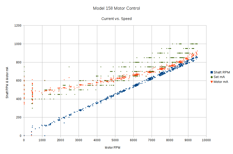
Now that the Arduino can set the current limiter, then measure the motor RPM, shaft RPM, and actual motor current, I can make plots like this:
Shaft speed and motor current vs RPM
The data comes from a routine that increments the setpoint current by 50 mA every five seconds, bouncing off 250 mA on the low end and 1 A on the high end, and writes the values to the serial port every half second. The actual current need not match the setpoint current, because it’s running open loop, and I haven’t done much in the way of calibration, so these represent interesting trends rather than dependable data points.
The eyeballometric slope down the middle of that blue smear comes out spot on 0.90, making the belt reduction 11.1 in good agreement with the results of those pulses.
The motor starts turning at 650 mA and will continue running down to maybe 500 mA, but with essentially zero low-end torque.
The horizontal range of green dots at each current setting shows that, as expected, the setpoint current has only a vague relation to the resulting motor speed: setting 800 mA will produce a speed between 5500 RPM and 9000 RPM, for sure. The actual motor current resulting from a given DAC output depends on the various transistor gains, all of which depend on temperature, which depends on how long the firmware has been running the motor at which speeds. Plenty of variation to go around.
The red points show that the actual motor current, as measured by the Hall effect sensor, generally lies below the green setpoint values, so better calibration is in order. Temperature effects turn accurate open-loop calibration into a fool’s errand, but we can do better than what you see there.
However, those red points do cluster much better, particularly between 6000 and 9000 RPM. You still can’t depend on the correlation, though, because the motor runs with a constant load here. In real life, the load will vary and so will the current required to maintain a given speed.
The green setpoints diverge from the red measurements at the high end, because the current limiter stops having much of an effect when the motor runs flat-out and sets its own current. After all, the original carbon-disk rheostat connected the line voltage directly across the motor, at which point the motor’s 100 W rating comes into play and limits the current to a nice sine wave with 1 A peaks.
Because the ET227 transistor acts as a current limiter, the motor current waveform has flat tops at the level set by the DAC voltage. However, the current depends strongly on the temperature of all those transistor junctions, with some commutation noise mixed in for good measure, so the firmware must measure the actual current to know what’s going on out there.
Here’s one way to pull that off:
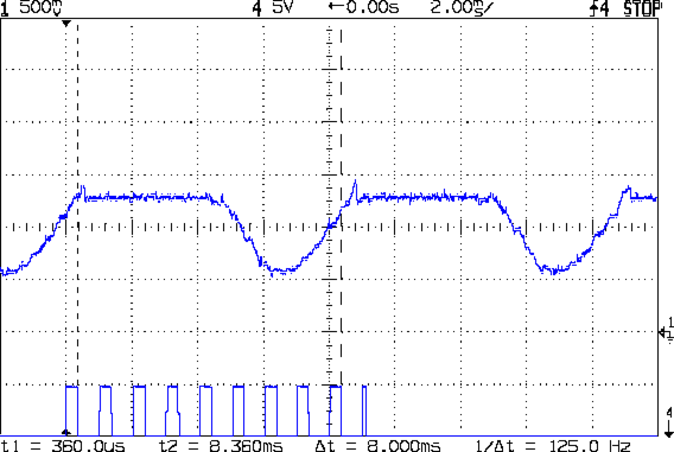
Motor current – ADC sample timing
The upper waveform shows the motor current sporting flat tops at 650 mA.
The lower waveform marks the current measurement routine, with samples taken just before the falling edge of the first nine pulses. The (manually tweaked) delay between the samples forces them to span one complete cycle of the waveform, but they’re not synchronized to the power line. Remember that the motor runs from a full wave rectifier, so each “cycle” in that waveform is half of a normal power line cycle.
Given an array containing those nine samples, the routine must return the maximum value of the waveform, ignoring the little glitch at the start of the flat top and taking into consideration that the waveform won’t have a flat top (or much of a glitch) when the current “limit” exceeds the maximum motor current.
After a bit of fumbling around with the scope and software, the routine goes like this:
Collect samples during one current cycle
Sort in descending order
Ignore highest sample
Return average of next two highest samples
Given that the array has only nine samples, I used a quick-and-dirty bubble sort. The runt pulse at the end of the series in the bottom waveform brackets the sort routine, so it’s not a real time killer.
Seeing as how this is one of the very few occasions I’ve had to sort anything, I wheeled out the classic XOR method of exchanging the entries. Go ahead, time XOR against swapping through a temporary variable; it surely doesn’t make any difference at all on an 8-bit microcontroller.
The sampling code, with all the tracing stuff commented out:
//------------------
// Sample current along AC waveform to find maximum value
//	this is blocking, so don't call it every time around the main loop!

#define NUM_I_SAMPLES	9

unsigned int SampleCurrent(byte PinNum) {

unsigned int Samples[NUM_I_SAMPLES];
unsigned int AvgSample;
byte i,j;

//	digitalWrite(PIN_SYNC,HIGH);
	for (i=0; i < NUM_I_SAMPLES; i++) {				// collect samples
//		digitalWrite(PIN_SYNC,HIGH);
		Samples[i] = ReadAI(PinNum);
//		digitalWrite(PIN_SYNC,LOW);
		delayMicroseconds(640);
	}
//	digitalWrite(PIN_SYNC,LOW);

//	digitalWrite(PIN_SYNC,HIGH);							// mark start of sorting
	for (i=0; i < (NUM_I_SAMPLES - 1); i++)
		for (j=0 ; j < (NUM_I_SAMPLES - 1 - i); j++)
			if (Samples[j] < Samples[j+1]) {
				Samples[j] ^= Samples[j+1];					// swap entries!
				Samples[j+1] ^= Samples[j];
				Samples[j] ^= Samples[j+1];
			}
//	digitalWrite(PIN_SYNC,LOW);								// mark end of sorting

//	printf("Samples: ");
//	for (i=0; i < NUM_I_SAMPLES; i++)
//		printf("%5d,",Samples[i]);

	AvgSample = (Samples[1] + Samples[2])/2;				// discard highest sample
//	printf(" [%5d]\r\n",AvgSample);

	return AvgSample;

}