The Smell of Molten Projects in the Morning

Ed Nisley's Blog: Shop notes, electronics, firmware, machinery, 3D printing, laser cuttery, and curiosities. Contents: 100% human thinking, 0% AI slop.

Tag: Sewing

Fabric arts and machines

  • Kenmore 158: Presser Foot Screw Shrink

    Mary started doing “ruler quilting” that involves sewing seams aligned with templates, only to find that the thumbscrew holding the (modified) presser foot obscures the view to the left of the needle:

    Kenmore Model 158 - OEM Presser Foot Screw
    Kenmore Model 158 – OEM Presser Foot Screw

    The screw looked to be 6-32 and I wanted to use a socket head cap screw, but thread turns out to be 6-40. Having previously bought the Brownell’s Fillister Head Screw Assortment specifically to solve that problem, all I had to do was cut the screw to length:

    Kenmore Model 158 - Small Presser Foot Screw
    Kenmore Model 158 – Small Presser Foot Screw

    The washer epoxied to the screw provides a bit more bearing surface.

    Rather than putz with a screwdriver, this handle locates itself around the screw head; turn until the blade clicks into the screw slot, then tighten or loosen as needed:

    Kenmore Model 158 - Presser Foot - Driver and Screw
    Kenmore Model 158 – Presser Foot – Driver and Screw

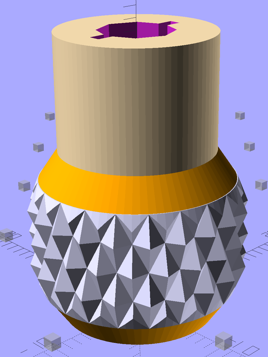
    The chubby driver handle descends directly from the Sherline tommy bar handles and four-jaw chuck speed keys:

    Presser Foot Screw Driver - solid model
    Presser Foot Screw Driver – solid model

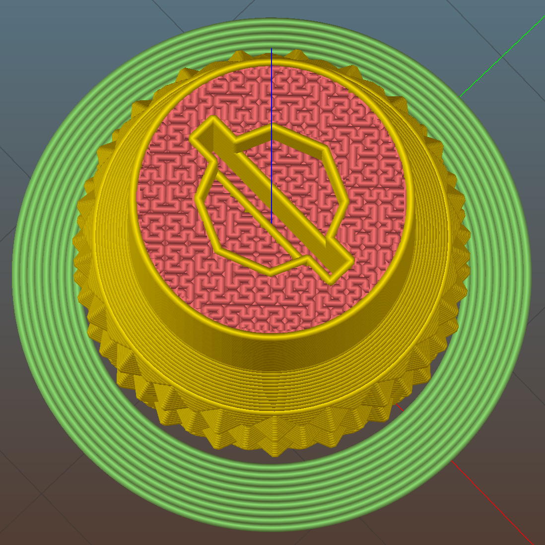
    The slot holds a chunk of spring steel (barely visible in the driver’s snout in group photo above) that accounts for the fat shaft around the screw head:

    Presser Foot Screw Driver - top - Slic3r
    Presser Foot Screw Driver – top – Slic3r

    I think the shaft could be a few millimeters narrower, but a bit of meat around the ends of the blade will support it against the torque.

    The screw head slot is about 1 mm and the blade is 0.75 mm. I chopped the blade to fit by whacking the spring with a poorly tempered cold chisel, then flexing across the impact line until it broke. That chisel needed sharpening anyhow.

    A dab of epoxy along the slot edges holds the blade in place. I inserted it flush with the top of the socket, then lined up the screw and pushed, with the steel bottomed out in the screw head and riding down for a perfect fit.

    Then it’s all good!

    The OpenSCAD source code:

    // Presser Foot Screw Driver for Kenmore Model 158
    // Ed Nisley - KE4ZNU - December 2015
    
    use <knurledFinishLib_v2.scad>
    
    //- Extrusion parameters must match reality!
    //  Print with 2 shells and 3 solid layers
    
    ThreadThick = 0.20;
    ThreadWidth = 0.40;
    
    HoleWindage = 0.3;			// extra clearance to improve hex socket fit
    
    Protrusion = 0.1;			// make holes end cleanly
    
    inch = 25.4;
    
    //----------------------
    // Dimensions
    
    SocketDia = 5.75;				// generous fit on 6-40 fillister screw head
    SocketDepth = 3.2;
    
    Blade = [9.0,1.0,ceil(SocketDepth + 5)];		// inserted metal driver blade
    echo(str("Blade: ",Blade));
    
    ShaftDia = 1.5*Blade[0];		// un-knurled section diameter
    ShaftLength = 10.0;				//  ... length
    
    KnurlLen = 10.0;				// length of knurled section
    KnurlDia = 18.0;				//   ... diameter at midline of knurl diamonds
    KnurlDPNom = 30;				// Nominal diametral pitch = (# diamonds) / (OD inches)
    
    DiamondDepth = 1.0;				//   ... depth of diamonds
    DiamondAspect = 2;				// length to width ratio
    
    KnurlID = KnurlDia - DiamondDepth;		// dia at bottom of knurl
    
    NumDiamonds = ceil(KnurlDPNom * KnurlID / inch);
    echo(str("Num diamonds: ",NumDiamonds));
    
    NumSides = 4*NumDiamonds;		// 4 facets per diamond
    
    KnurlDP = NumDiamonds / (KnurlID / inch);				// actual DP
    echo(str("DP Nom: ",KnurlDPNom," actual: ",KnurlDP));
    
    DiamondWidth = (KnurlID * PI) / NumDiamonds;
    
    DiamondLenNom = DiamondAspect * DiamondWidth;					// nominal diamond length
    DiamondLength = KnurlLen / round(KnurlLen/DiamondLenNom);		//  ... actual 
    
    TaperLength = 0.50*DiamondLength;
    
    KnobOAL = 2*TaperLength + KnurlLen + ShaftLength;
    
    //----------------------
    // Useful routines
    
    module PolyCyl(Dia,Height,ForceSides=0) {			// based on nophead's polyholes
    
      Sides = (ForceSides != 0) ? ForceSides : (ceil(Dia) + 2);
    
      FixDia = Dia / cos(180/Sides);
    
      cylinder(r=(FixDia + HoleWindage)/2,
               h=Height,
    	   $fn=Sides);
    }
    
    module ShowPegGrid(Space = 10.0,Size = 1.0) {
    
      Range = floor(50 / Space);
    
    	for (x=[-Range:Range])
    	  for (y=[-Range:Range])
    		translate([x*Space,y*Space,Size/2])
    		  %cube(Size,center=true);
    }
    
    
    //- Build it
    
    ShowPegGrid();
    
    difference() {
    	union() {
    		render(convexity=10)
    		translate([0,0,TaperLength])			// knurled cylinder
    			knurl(k_cyl_hg=KnurlLen,
    				  k_cyl_od=KnurlDia,
    				  knurl_wd=DiamondWidth,
    				  knurl_hg=DiamondLength,
    				  knurl_dp=DiamondDepth,
    				  e_smooth=DiamondLength/2);
    		color("Orange")							// lower tapered cap
    		cylinder(r1=ShaftDia/2,
    					r2=(KnurlDia - DiamondDepth)/2,
    					h=(TaperLength + Protrusion),
    					$fn=NumSides);
    		color("Orange")							// upper tapered cap
    		translate([0,0,(TaperLength + KnurlLen - Protrusion)])
    			cylinder(r2=ShaftDia/2,
    					r1=(KnurlDia - DiamondDepth)/2,
    					h=(TaperLength + Protrusion),
    					$fn=NumSides);
    		color("Moccasin")						// cylindrical extension
    		translate([0,0,(2*TaperLength + KnurlLen - Protrusion)])
    			cylinder(r=ShaftDia/2,h=(ShaftLength + Protrusion),$fn=NumSides);
    
    	}
    	
    	translate([0,0,(KnobOAL - SocketDepth + Protrusion)])
    		PolyCyl(SocketDia,(SocketDepth + Protrusion),8);	// screw head socket
    		
    	translate([0,0,KnobOAL - (Blade[2] - Protrusion)/2])
    		cube(Blade + [0,0,Protrusion],center=true);
    }
    
  • Kenmore 158: Largest Spool Holder, Now With Eye Protection

    A tip o’ the cycling helmet to Mike for catching this oversight:

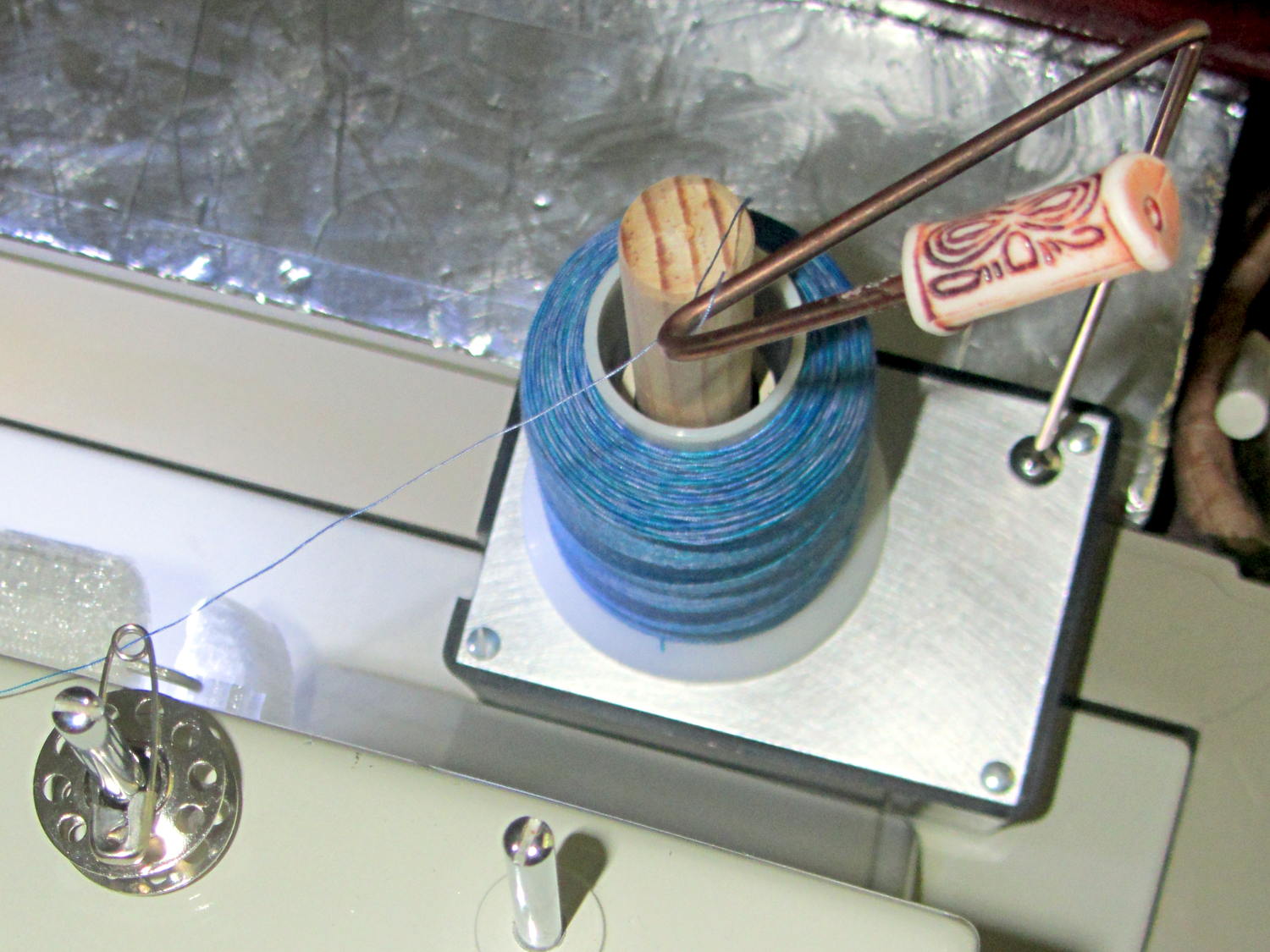
    Large spool holder - added bead and guide
    Large spool holder – added bead and guide

    I’d rounded the end of that steel rod, it stands behind the sewing machine, and blah blah blah. He was right: it needed a bead. That’s a fancy one pilfered from our Larval Engineer’s stash, held in place by a blob of fast-cure epoxy.

    Selah.

    The safety pin atop the bobbin on the left spool pin feeds the thread into the machine’s upper thread guide at the proper angle to make it all work; a direct line from the spool holder hook isn’t quite right.

  • Kenmore 158: Large(st) Spool Holder

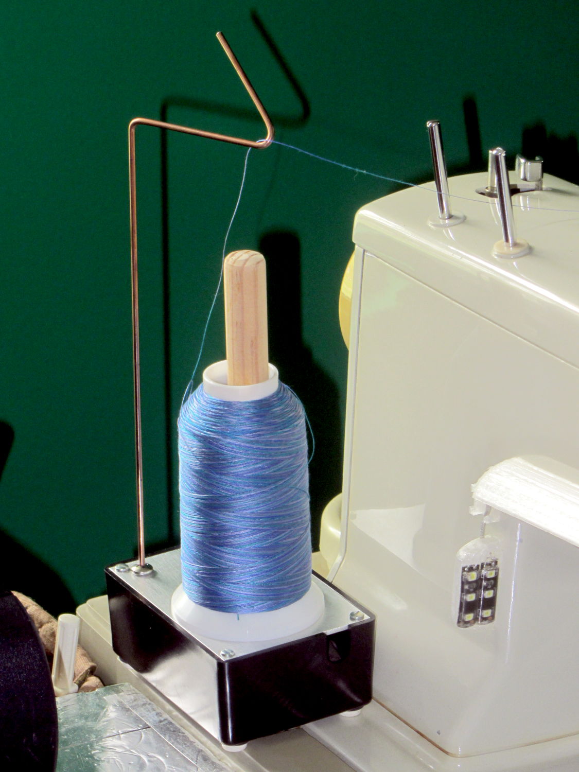
    Large quilting projects require lots of thread, beyond the capacity of the previous spool adapter, so we came up with a different solution:

    Large spool holder
    Large spool holder

    These are cheap & readily available from the usual sources, but recent reviews indicate that the “metal” base has become plastic and the build quality isn’t anything to rejoice over. My feeling is that if it’s going to become a shop project anyway, I should just conjure something suitable from the heap.

    The base is a random plastic project box that came with a flimsy sheet-steel top, which I replaced with a rectangle of 0.1 inch = 2.5 mm aluminum plate for more heft. The box is filled with 1.5 pounds of wheel weights, so it’s not going anywhere on its own. The silicone rubber feet probably don’t add much to the project, but why not use ’em?

    The feed hook started life as copper-flashed welding filler rod, smooth to the thread and pleasant to the eye, sitting in a hole drilled into a stainless steel 10-32 screw. It’s long enough to feed the thread just above the Kenmore’s top surface. A hook works better than an eyelet: just pass the thread over the hook and you’re done.

    The central shaft is a wood dowel, shaped & sanded on the (metal) lathe, held in place by another 10-32 screw. Inside the spool sits a length of “3/4 inch” CPVC pipe (ID = 0.7 inch, OD = 0.875 inch, gotta love those plumbing measurements) that’s a sloppy fit in the just-over 1 inch spool ID.

    The smaller spools fit directly on the dowel, perhaps atop the CPVC sleeve.

    This seems to work OK, but I’m going to trim the dowel down to just over the length of the spool, so the thread will feed without touching the wood. I thought stacking the smaller spools atop the CPVC sleeve made sense, but that turned out to not be the case.

    Took about an hour to conjure with found materials and without a hint of 3D printing…


  • Kenmore 158 UI: Pastel Buttons

    The user community asked for toned-down buttons, in place of my rather garish color scheme. A bit of twiddling with the Hue parameter produced these buttons:

    Kenmore 158 UI - Pastel Buttons
    Kenmore 158 UI – Pastel Buttons

    Which look pretty good in context:

    Kenmore 158 UI - Pastel buttons
    Kenmore 158 UI – Pastel buttons

    The Bash script, which includes Unicode characters that may confuse your browser:

    ND=50
    ./mkBFam.sh NdDn  $ND ⤓ 
    ./mkBFam.sh NdUp  $ND ⤒
    ./mkBFam.sh NdAny $ND ⛀ 80 80 40
    #./mkBFam.sh NdAny $ND  ⛂ 80 80 40
    #./mkBFam.sh NdAny $ND 🍥 80 80 40
    
    PD=14
    ./mkBFam.sh PdOne $PD One 120 80 
    ./mkBFam.sh PdFol $PD Follow 120 80 
    ./mkBFam.sh PdRun $PD Run 120 80 
    
    SM=44
    ./mkBFam.sh SpMax $SM  🏃 80 80 40
    ./mkBFam.sh SpMed $SM  🐇 80 80 40
    ./mkBFam.sh SpLow $SM  🐌
    
    montage *bmp -tile 3x -geometry +2+2 Buttons.png
    display Buttons.png
    

    So far, so good…

  • Kenmore 158 UI: Button Rework

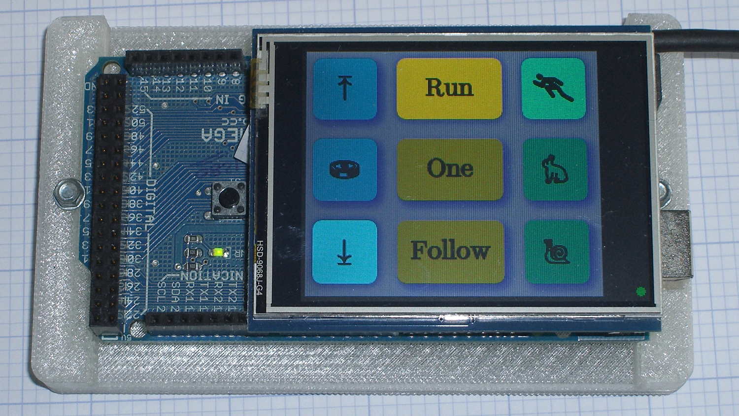
    Simplifying the Kenmore 158 UI’s buttons definitely improved the user experience:

    Kenmore 158 Controller - Simplified Buttons
    Kenmore 158 Controller – Simplified Buttons

    The trick depends on specifying the colors with HSB, rather than RGB, so that the buttons in each row have the same hue and differ in saturation and brightness. The Imagemagick incantations look like this:

    • Disabled: hsb\(${HUE}%,50%,40%\)
    • Unselected: hsb\(${HUE}%,100%,70%\)
    • Selected: hsb\(${HUE}%,100%,100%\)

    For whatever reason, the hue must be a percentage if the other parameters are also percentages. At least, I couldn’t figure out how to make a plain integer without a percent sign suffix work as a degree value for hue.

    Anyhow, in real life they look pretty good and make the selected buttons much more obvious:

    Kenmore 158 UI - Simplified buttons - contrast stretch
    Kenmore 158 UI – Simplified buttons – contrast stretch

    The LCD screen looks just like that; I blew out the contrast on the surroundings to provide some context. The green square on the left is the Arduino Mega’s power LED, the purple dot on the right is the heartbeat spot.

    The new “needle stop anywhere” symbol (left middle) is the White Draughts Man Unicode character: ⛀ = U+26C0. We call them checkers here in the US, but it’s supposed to look like a bobbin, as you must disengage the handwheel clutch and stop the main shaft when filling a bobbin; the needle positioning code depends on the shaft position sensor.

    Weirdly, Unicode has no glyphs for sewing, not even a spool of thread, although “Fish Cake With Swirl” (🍥 = U+1F365) came close. Your browser must have access to a font with deep Unicode support in order to see that one…

    You can’t say I didn’t try:

    Unicode characters - bobbin-like shapes
    Unicode characters – bobbin-like shapes

    The script that generates all the buttons:

    ./mkBFam.sh NdDn  9 ⤓
    ./mkBFam.sh NdUp  9 ⤒
    ./mkBFam.sh NdAny 9 ⛀ 80 80 40
    ./mkBFam.sh PdOne 33 One 120 80
    ./mkBFam.sh PdFol 33 Follow 120 80
    ./mkBFam.sh PdRun 33 Run 120 80
    ./mkBFam.sh SpMax 83  🏃 80 80 40
    ./mkBFam.sh SpMed 83  🐇 80 80 40
    ./mkBFam.sh SpLow 83  🐌
    montage *bmp -tile 3x -geometry +2+2 Buttons.png
    display Buttons.png
    

    The script that generates all the versions of a single button:

    # create family of button images
    # Ed Nisley - KE4ZNU
    # March 2015
    
    [ -z $1 ] && FN=Test || FN=$1
    [ -z $2 ] && HUE=30  || HUE=$2
    [ -z $3 ] && TXT=x   || TXT=$3
    [ -z $4 ] && SX=80   || SX=$4
    [ -z $5 ] && SY=80   || SY=$5
    [ -z $6 ] && PT=25   || PT=$6
    [ -z $7 ] && BDR=10  || BDR=$7
    
    echo fn=$FN hue=$HUE txt=$TXT sx=$SX sy=$SY pt=$PT bdr=$BDR
    
    echo Working ...
    
    echo Shape
    
    echo Buttons
    echo  .. Disabled
    convert -size ${SX}x${SY} xc:none \
      -fill hsb\(${HUE}%,50%,40%\) -draw "roundrectangle $BDR,$BDR $((SX-BDR)),$((SY-BDR)) $((BDR-2)),$((BDR-2))" \
      ${FN}_s.png
    convert ${FN}_s.png \
      -font /usr/share/fonts/custom/Symbola.ttf  -pointsize ${PT}  -fill gray20  -stroke gray20 \
      -gravity Center  -annotate 0 "${TXT}"  -trim -repage 0x0+7+7 \
      \( +clone -background navy -shadow 80x4+4+4 \) +swap \
      -background snow4  -flatten \
      ${FN}0.png
    
    echo  .. Enabled
    convert -size ${SX}x${SY} xc:none \
      -fill hsb\(${HUE}%,100%,70%\) -draw "roundrectangle $BDR,$BDR $((SX-BDR)),$((SY-BDR)) $((BDR-2)),$((BDR-2))" \
      ${FN}_s.png
    convert ${FN}_s.png \
      -font /usr/share/fonts/custom/Symbola.ttf  -pointsize $PT  -fill black  -stroke black \
      -gravity Center  -annotate 0 "${TXT}"  -trim -repage 0x0+7+7 \
      \( +clone -background navy -shadow 80x4+4+4 \) +swap \
      -background snow4  -flatten \
      ${FN}1.png
    
    echo  .. Pressed
    convert -size ${SX}x${SY} xc:none \
      -fill hsb\(${HUE}%,100%,100%\) -draw "roundrectangle $BDR,$BDR $((SX-BDR)),$((SY-BDR)) $((BDR-2)),$((BDR-2))" \
      ${FN}_s.png
    convert ${FN}_s.png \
      -font /usr/share/fonts/custom/Symbola.ttf  -pointsize ${PT}  -fill black  -stroke black \
      -gravity Center  -annotate 0 "${TXT}"  -trim -repage 0x0+7+7 \
      \( +clone -background navy -shadow 80x4+4+4 -flip -flop \) +swap \
      -background snow4  -flatten \
      ${FN}2.png
    
    echo BMPs
    for ((i=0 ; i <= 2 ; i++))
    do
     convert ${FN}${i}.png -type truecolor ${FN}${i}.bmp
    # display -resize 300% ${FN}${i}.bmp
    done
    
    rm ${FN}_s.png ${FN}?.png
    
    echo Done!
    
  • Kenmore 158: Bobbin Winder Repair

    For reasons which are, trust me on this, not relevant here, we now have a third Kenmore 158 sewing machine: a freebie that sat under a roof leak in an unused room some years ago and wasn’t cleaned before being stored. Even though not much water got inside the covers, the bobbin winder shaft froze solid.

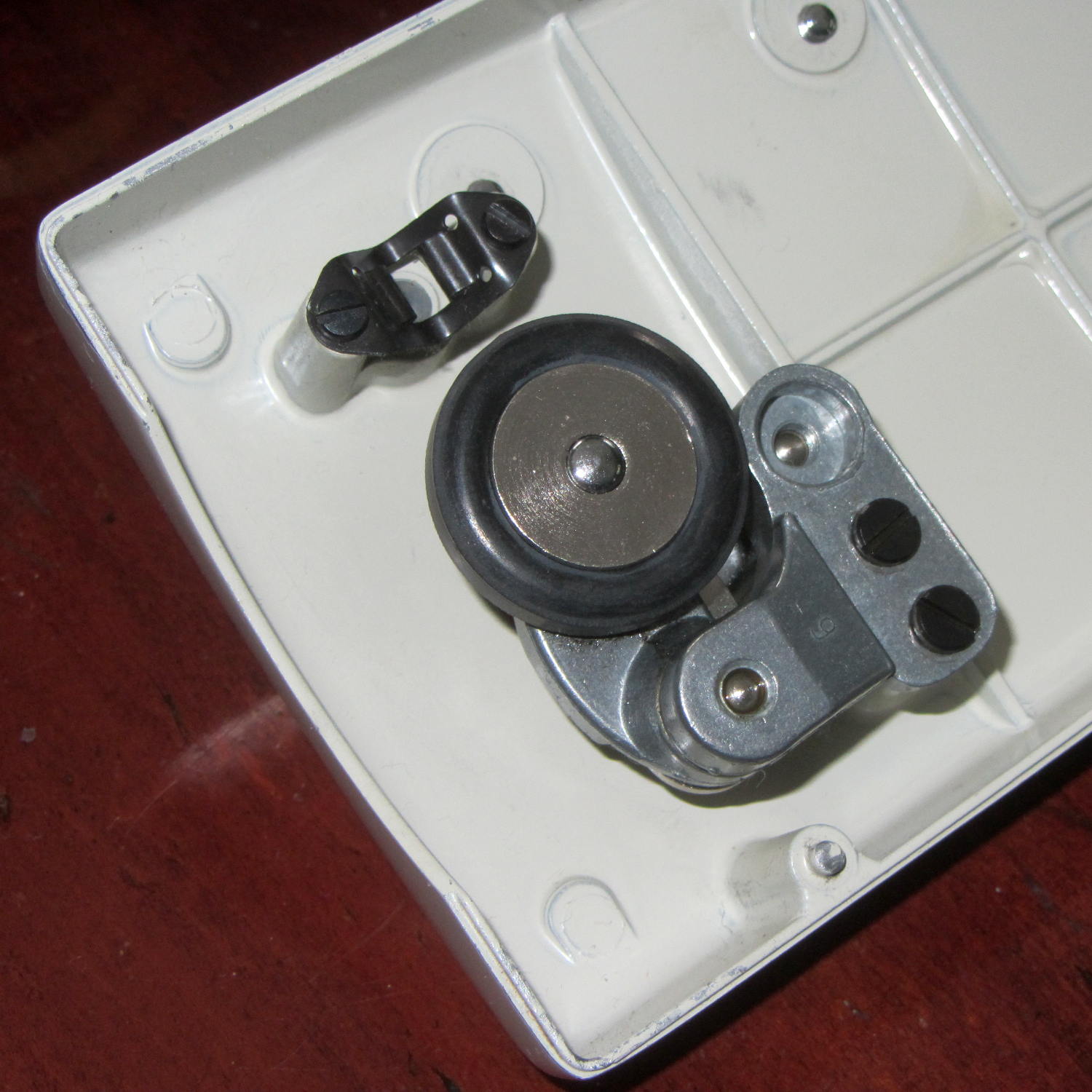
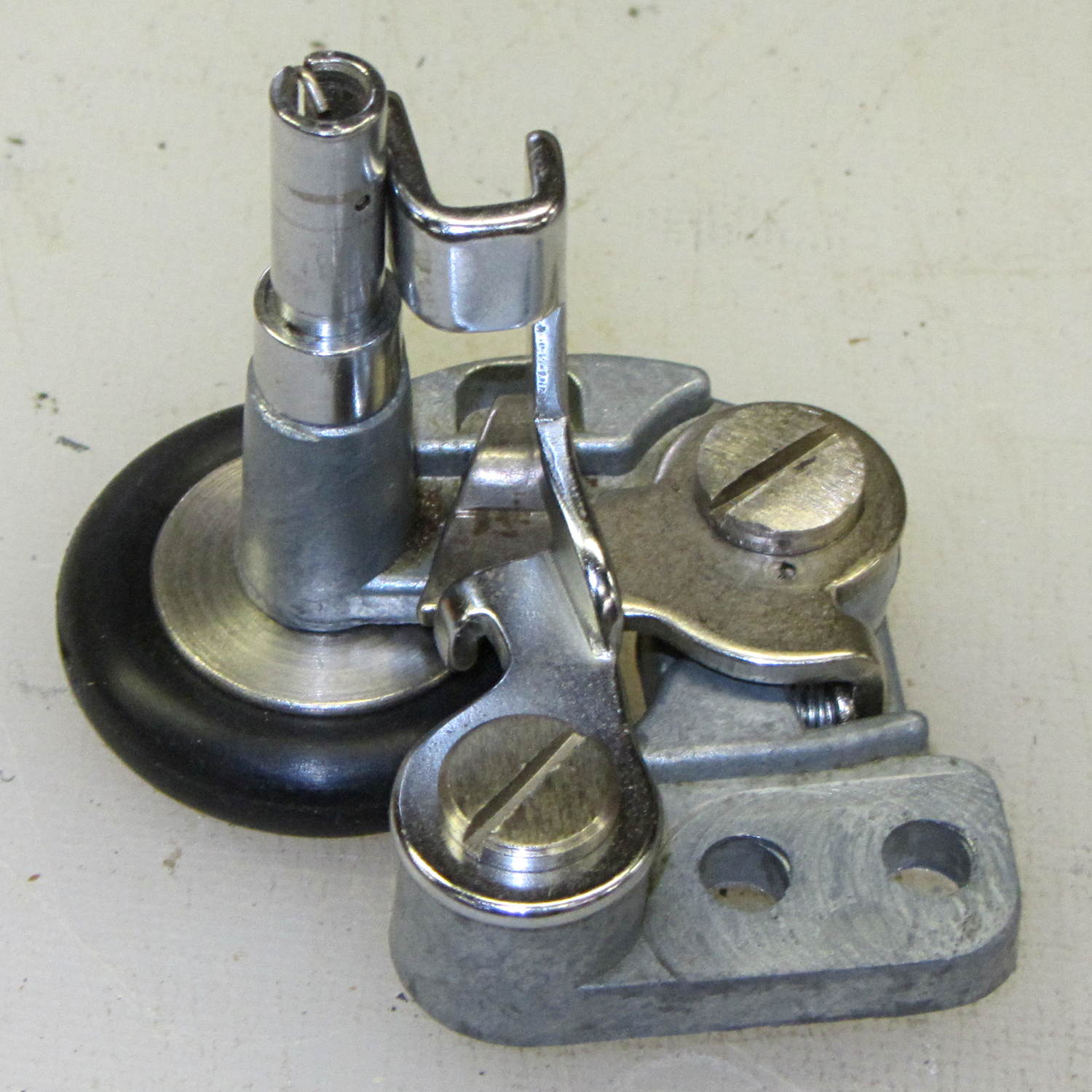
    Two black screws hold it to the cover and provide a slight adjustment of the tire-to-handwheel distance:

    Bobbin Winder - old tire
    Bobbin Winder – old tire

    Prior to this adventure, I soaked the shaft in penetrating oil for a week or two, but to no avail.

    I didn’t take any before-the-repair photos, but it looked like this afterward, with the new tire installed…

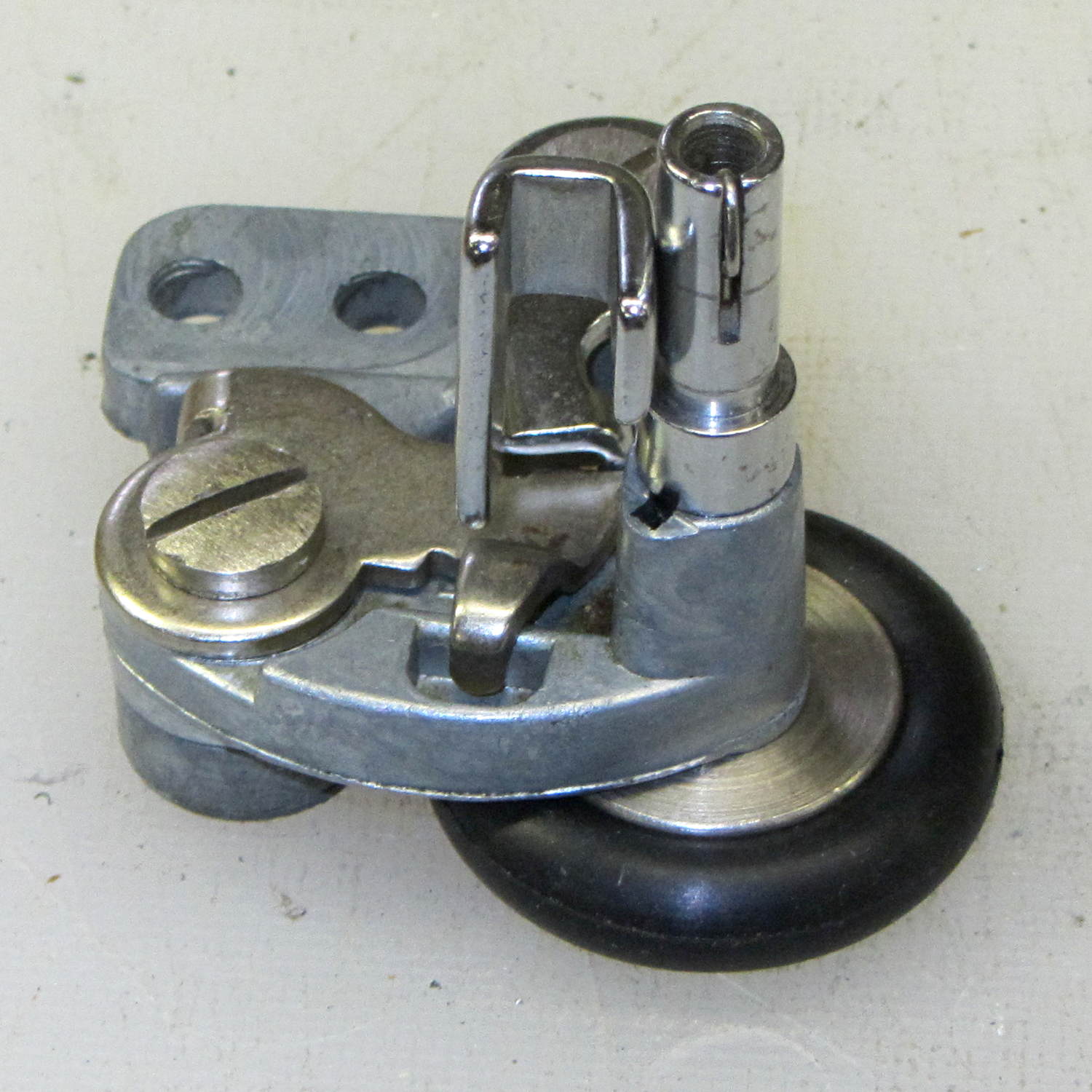
    From the top right (looking over the handwheel):

    Bobbin Winder - assembled - top right
    Bobbin Winder – assembled – top right

    Notice the small rectangular hole just below the larger section of the shaft in the protruding part of the pot metal housing. That’s supposed to be an oil hole, but it’s also a fine water inlet.

    From the top left:

    Bobbin Winder - assembled - top left
    Bobbin Winder – assembled – top left

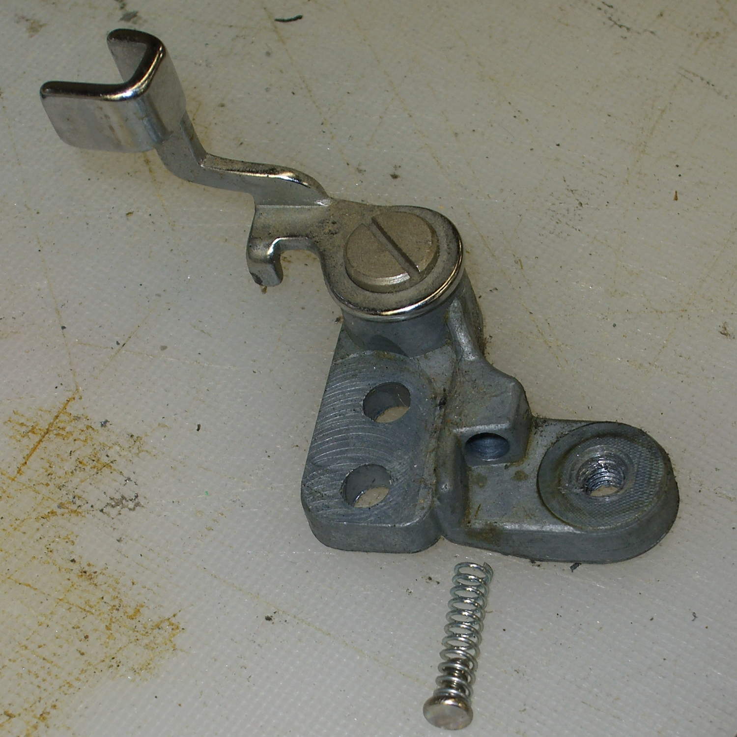
    The two obvious screws remove the obvious parts, but beware the compression spring:

    Bobbin Winder - fill sense lever
    Bobbin Winder – fill sense lever

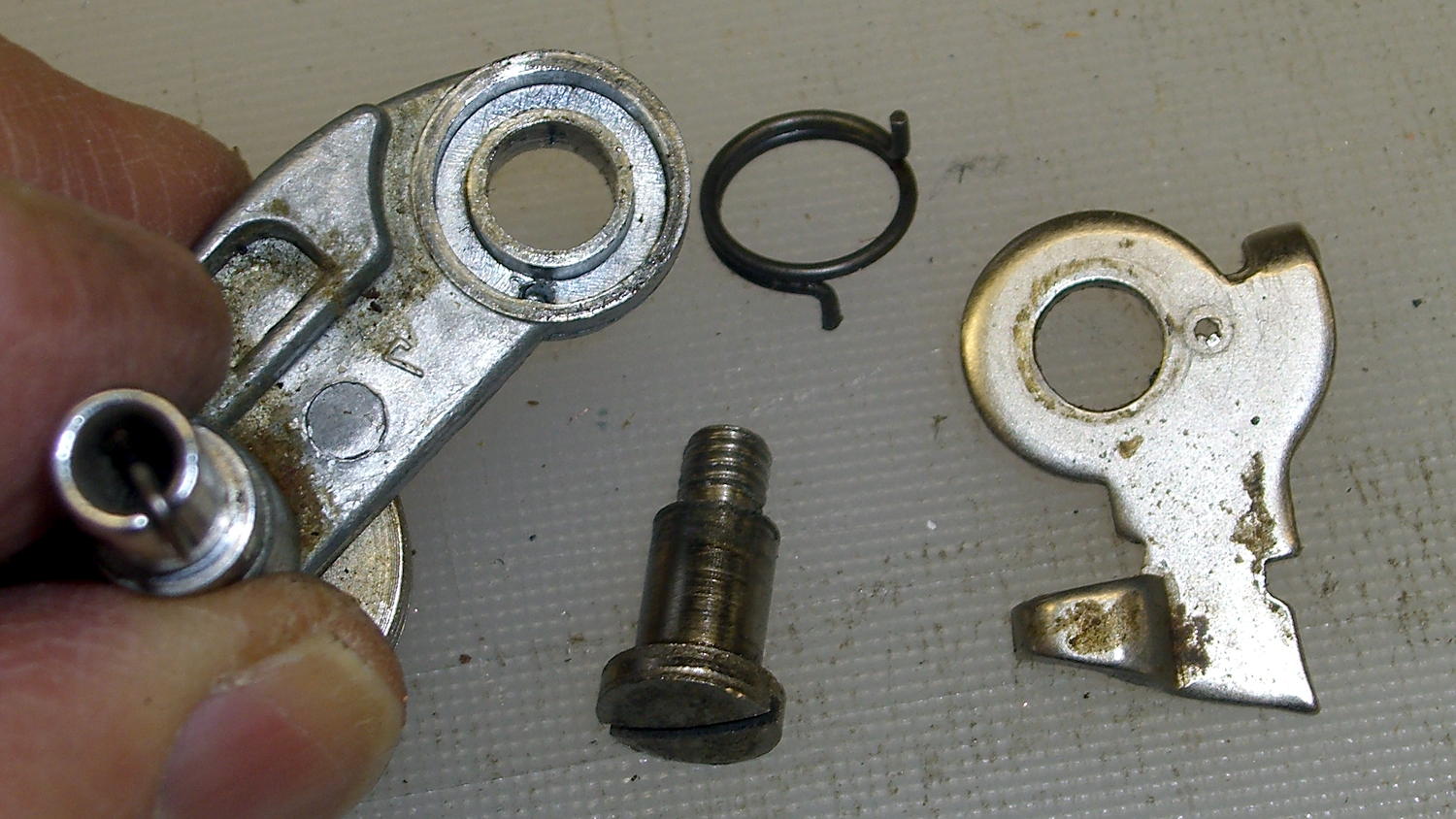
    And the torsion spring:

    Bobbin Winder - drive latch
    Bobbin Winder – drive latch

    Some experimentation with a strap wrench rotated the wheel on the (still firmly frozen) shaft, which suggested the joint was a press fit without a setscrew, splines, or adhesive.

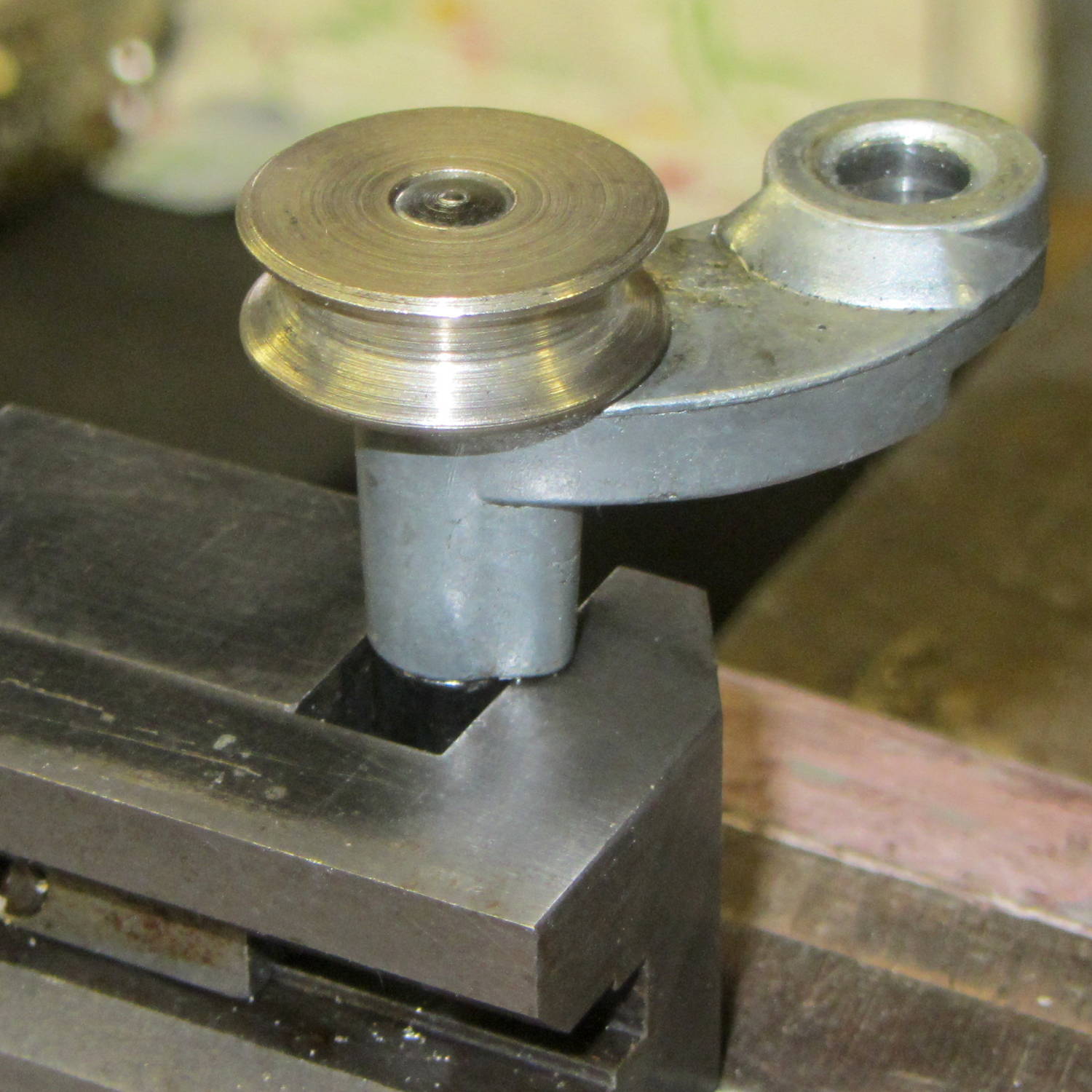
    Grabbing the shaft lightly in a machinist’s vise, resting it atop the bench vise, and giving it a few shots with a drift punch drove it downward through the housing:

    Bobbin Winder - driving out spindle
    Bobbin Winder – driving out spindle

    More gentle beating produced this heartrending scene:

    Bobbin Winder - corroded shaft
    Bobbin Winder – corroded shaft

    Water just isn’t any good at all for unlubricated steel in a pot-metal bushing…

    Anyhow, the shaft & housing cleaned up well, although they look a tad grody, and everything went back together in the reverse order.

    I added a drop of light oil through the lube port, chucked the shaft in the drill press, spun it for a minute at low speed to wear off a slight binding, and it’s all good again.

  • Kenmore 158: Bobbin Winder Tires

    The bobbin winder atop the Kenmore 158 sewing machine has a rubber tire that contacts a ribbed ring on the inside surface of the handwheel; the clutch knob disengages the main shaft and you run the motor at top speed. As you’d expect, both age and wear take their toll on the rubber, to the extent that the winder on Mary’s machine stopped turning. I swapped it for the slightly less decrepit winder on the Crash Test Dummy, but that was obviously a stop-gap measure.

    I mistakenly thought the metal wheel consisted of two plates that clamped a rubber disk in place, with no possibility of removal:

    Bobbin Winder - old tire
    Bobbin Winder – old tire

    The fact that the spare parts list didn’t include the rubber disk helped convince me.

    Eventually, I stumbled over replacement “tires” on, of course, eBay that suggested how to dismount them:

    Bobbin Winder - wheel and tires
    Bobbin Winder – wheel and tires

    Yup, that sucker slides right off.

    Anyhow, the replacements seem to be standard industrial O-rings, rather than the original tire with a flattened rim:

    Bobbin Winder - old vs new tire
    Bobbin Winder – old vs new tire

    The new tires measure 28.94 mm OD on the bench (I don’t trust that last digit, either) and 29.56 mm OD installed. The (hardened and cracked) old tires measure 29.94, 30.06, and 30.28 mm OD on the bench; that’s a radius anywhere from 0.2 mm to 0.4 mm larger. The winder’s mounting screws provide a very small adjustment range that helps a bit.

    Knowing that I needed an O-ring, I checked the assortment of “standard size” O-rings I bought many, many years ago, which once again failed to offer up anything suitable. To the best of my knowledge, that kit has never had the right size; apparently, every application uses a different standard.

    The O-ring definitely puts less rubber on the handwheel than the tire, but seems to drive the bobbin winder well enough to fill a handful of bobbins without any of the previous drama.