The Smell of Molten Projects in the Morning

Ed Nisley's Blog: Shop notes, electronics, firmware, machinery, 3D printing, laser cuttery, and curiosities. Contents: 100% human thinking, 0% AI slop.

Tag: Sewing

Fabric arts and machines

  • OttLite LED Conversion

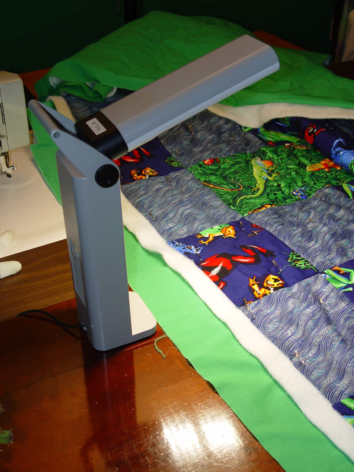
    Although Mary liked the illumination from her OttLite (an old 13 W fluorescent Folding Task Lamp), neither of us liked its tiny base and tippy nature. It recently fell / was dropped / jumped to its doom, smashing the CFL tube and wreaking havoc on the tiny plastic studs holding its large cast-iron weight and steel base in position. Given that the CFL ballast had started humming a while ago, I took it apart to see whether I could salvage anything from the rubble.

    Remove:

    • Four screws under the fuzzy felt feet
    • One screw under the label on the back
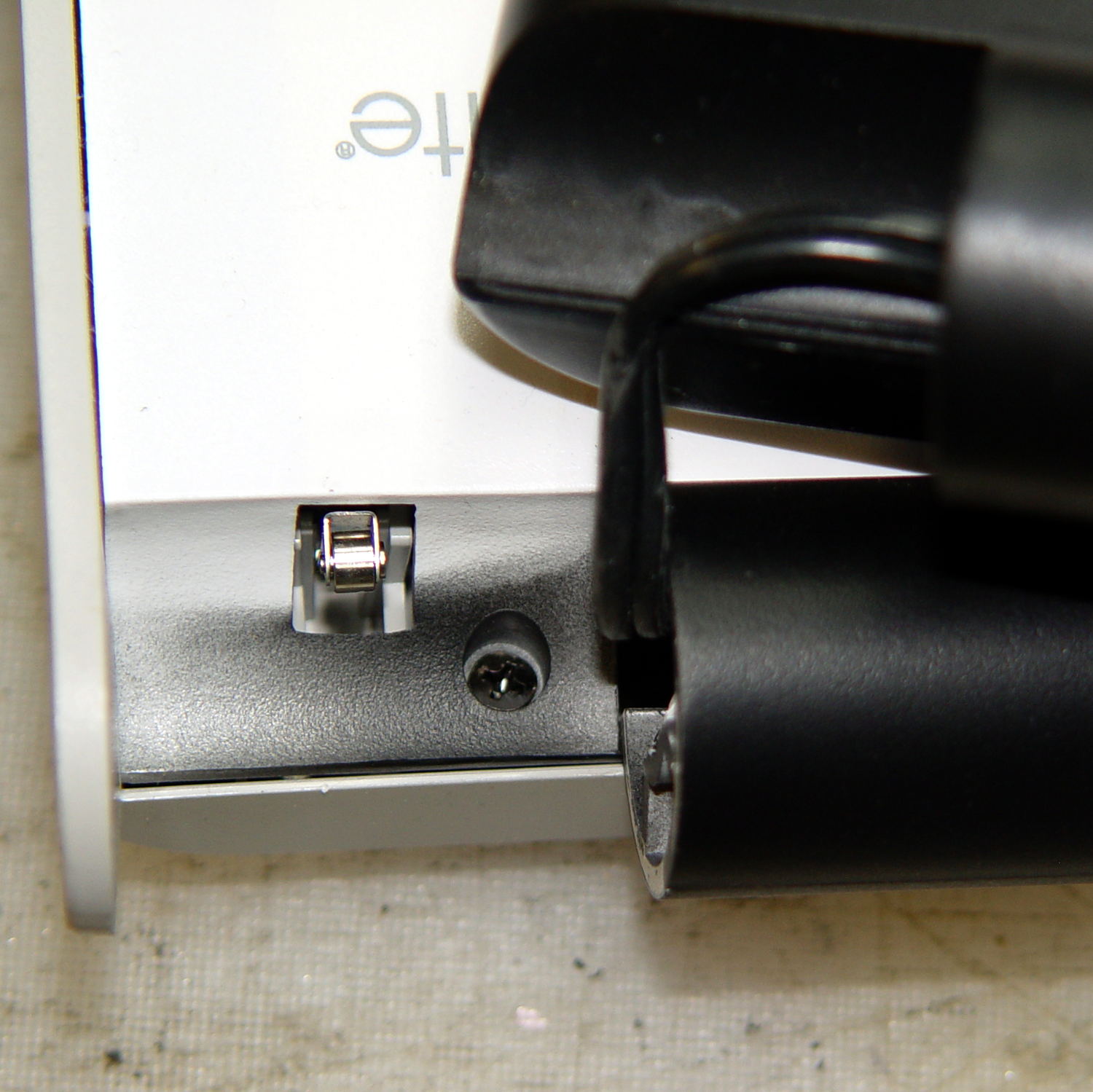
    • A final screw that becomes visible only after disemboweling the hinge assembly by unscrewing the obvious endcaps:
    OttLite LED Conversion - hinge screw
    OttLite LED Conversion – hinge screw

    Pull the hinge end of the white inside panel away from the outer stand at enough of an angle to disengage all three latches holding it to the base, then remove it just enough to let you start cutting wires around the ballast…

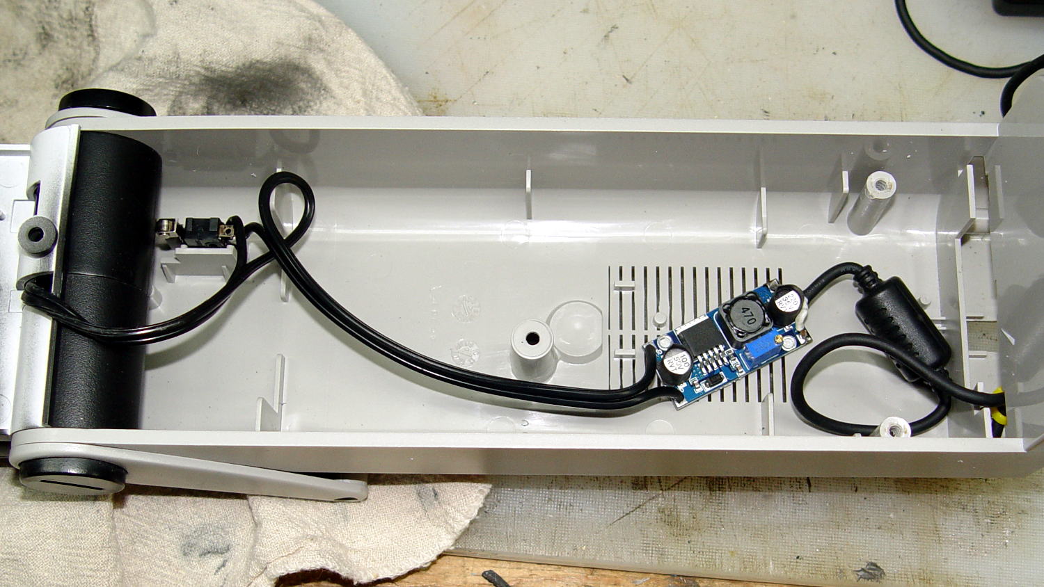
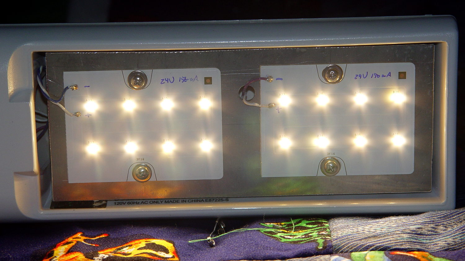
    I rebuilt the thing with a pair of 24 V 150 mA warm-white LED panels (good industrial surplus, not the usual cheap eBay crap) powered by a 19 V laptop adapter (from IBM, no less) through a (cheap eBay) boost converter sticky-foam-taped where the fluorescent ballast used to live:

    OttLite LED Conversion - boost supply wiring
    OttLite LED Conversion – boost supply wiring

    The power supply had only two conductors, the central wire surrounded by twisted shielding, and didn’t require a fussy interface. Hooray for simple bulk power supplies; I lopped off the connector and soldered the wires directly to the boost converter.

    The original lamp wiring has a 120 VAC switch inside the hinge that turned the lamp on as you raise the arm holding the CFL tube: exactly what I need for its new use. That eliminated figuring out how to crack the arm apart to rewire it.

    I harvested the base from a(nother) defunct CFL bulb:

    OttLite LED Conversion - harvested CFL base
    OttLite LED Conversion – harvested CFL base

    By soldering wires directly into the pins, I could reuse the existing CFL socket in the lamp arm, the existing wiring, and the switch.

    The LED panels dissipate 3-ish W each:

    OttLite LED Conversion - LED panel layout
    OttLite LED Conversion – LED panel layout

    They’re mounted on a 0.1 inch aluminum sheet from the heap that required exactly one saw cut to fit into the space available, so I defined it to be perfect. The 4-40 screws holding the panels in place continue through the plate and 3/8 inch aluminum standoffs into a quartet of knurled inserts epoxied into eyeballometrically match-drilled holes in the lamp arm:

    OttLite LED Conversion - epoxied threaded inserts
    OttLite LED Conversion – epoxied threaded inserts

    The faint yellowish discoloration from the CFL tube’s heat and UV is much more visible in real life, but nobody will ever see it again. The scrawled blue (+) and (-) marks give the socket polarity; it’s not mechanically polarized and a bit of care is in order. The black rectangle is actually a shiny metal sheet intended to reflect heat from the CFL tube’s base away from the plastic arm.

    I set the boost converter to 23.5 V, at which point the LED panels draw about 100 mA each and get just over uncomfortably warm after an hour or two:

    OttLite LED Conversion - in action
    OttLite LED Conversion – in action

    The panels run 120 °F = 50 °C and the SMD LEDs probably exceed 150 °F = 65 °C. The scant surplus doc touted “No heatsink required” and the single-sided FR4 PCB insulates the LEDs from the aluminum sheet, but I still smeared some heatsink compound behind the panels in the hopes of spreading the heat out a bit.

    I glued the shattered base studs back in place with IPS #3, surrounded them with generous epoxy fillets, plunked the cast iron weight in place atop some waxed paper to mold the epoxy to fit (and let me remove it again, if needs be), screwed everything together, and stuck a foam sheet over the steel base plate. It’s as tippy as before, but at least the LEDs won’t shatter if when it falls. It really needs a larger base; a polycarbonate plate might work, if only I could figure out how to attach it.

    All in all, the lamp looks good and the warm-white LEDs with DC drive don’t produce that horrible fluorescent flicker.

    The lamp now sports a label identifying it as a NisLite; because P-Touch labeler.

  • Streaming Player: Wireless Keypad

    Moving the streaming media player control panel across the Sewing Room for E-Z access:

    Wireless Keypad - colored labels
    Wireless Keypad – colored labels

    Stipulated: garish labels that don’t fit the keys well at all.

    I need more than one stream for testing; the only one that matters is Classical.

    The keypad uses the same 2.4 GHz ISM band as the Raspberry Pi’s Wifi radio, which means holding a key down (which should never happen) puts a dent in mplayer’s cache fill level. Even absent that interference, the WiFi link seems more than a little iffy, probably because it’s at the far end of the house and upstairs from the router.

    Other WiFi devices report that 2.4 GHz RF has trouble punching through the intervening fifty feet of hardwood floor (on the diagonal, the joists amount to a lot of wood) and multiple sets of doubled wallboard sheets; the RPi probably needs a better radio with an actual antenna. I did move the WiFi control channel away from the default used by the (relatively distant) neighbors, which seemed to improve its disposition.

  • Kenmore Model 158: Older Foot Pedal Resistor

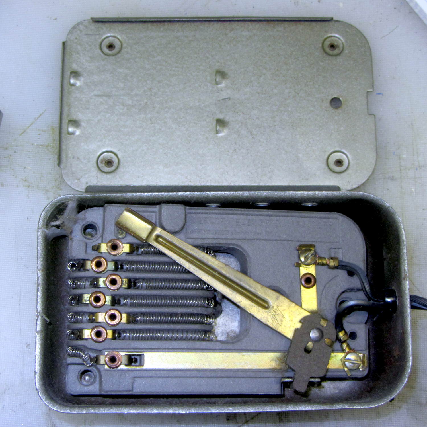
    Based on the paperwork tucked into the sewing table, the most recent Kenmore Model 158 sewing machine in our stable dates to 1972, a bit earlier than the others, and has a metal-cased foot pedal with a wire-wound resistor:

    Kenmore Model 158 - new-ish foot pedal resistor
    Kenmore Model 158 – new-ish foot pedal resistor

    The cord insulation stiffened up over the decades and I wanted to replace it, but the contacts in the sewing machine connector were spot-welded to the conductors with no room for teeny screws:

    Kenmore Model 158 - new-ish foot pedal connector
    Kenmore Model 158 – new-ish foot pedal connector

    I blew out the fuzz, put it back together, and it works pretty well, modulo the usual low torque at slow speeds issue.

    The discrete resistor taps produce a somewhat stepped response, but early reports suggest it’s not enough to be annoying; it’s much more stable than the carbon disks in the more recent pedals.

  • Sears Sewing Table: Sewing Machine Supports

    For reasons that should not require explanation by now, Mary just acquired a large sewing table (along with a Sears Kenmore Model 158 sewing machine that’s slightly older and fancier than the three we already have). The table has an opening fitted to the machine base, but the rubber pads atop the leveling screws had long since stiffened up and two screws were frozen in place. A few drops of penetrating oil released the screws and, mirable dictu, they have ordinary 6-32 threads.

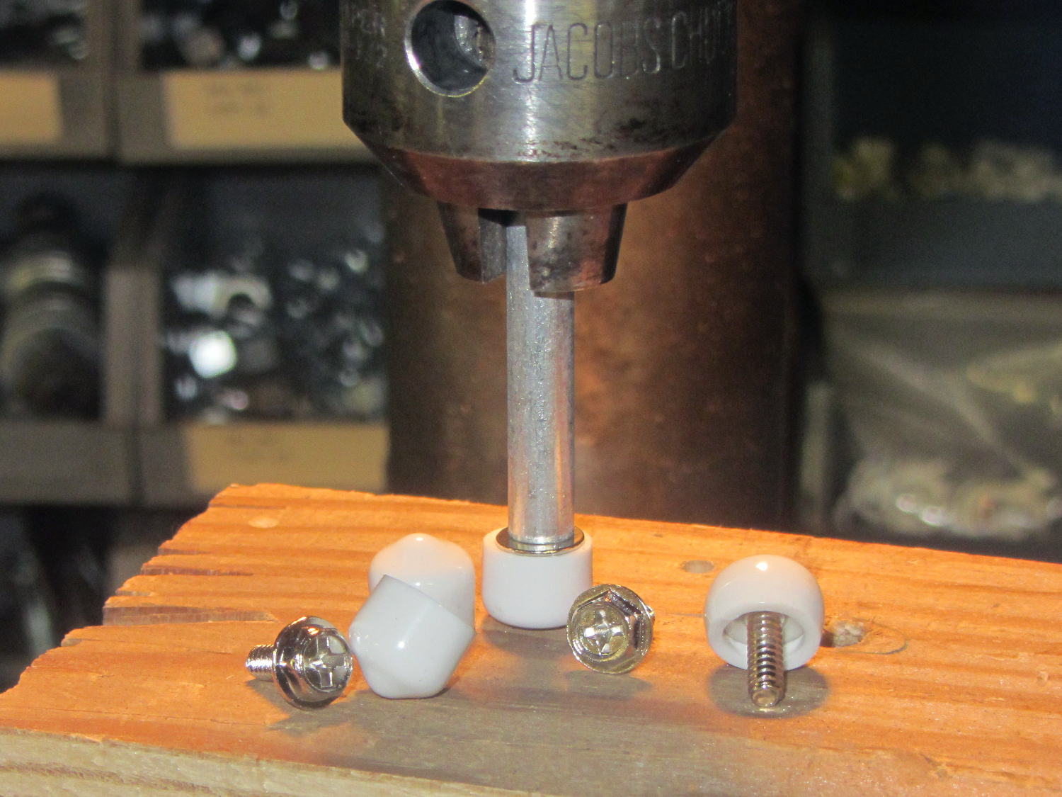
    Some rummaging turned up four PC case screws and soft caps intended for wire shelves, which easily combined into replacement machine supports:

    Sewing Machine Supports - inserting screws
    Sewing Machine Supports – inserting screws

    Once again, I’m using the drill press as a low-force arbor press, with a chunk of aluminum tubing to shove the screw flange into the slightly smaller plastic cap.

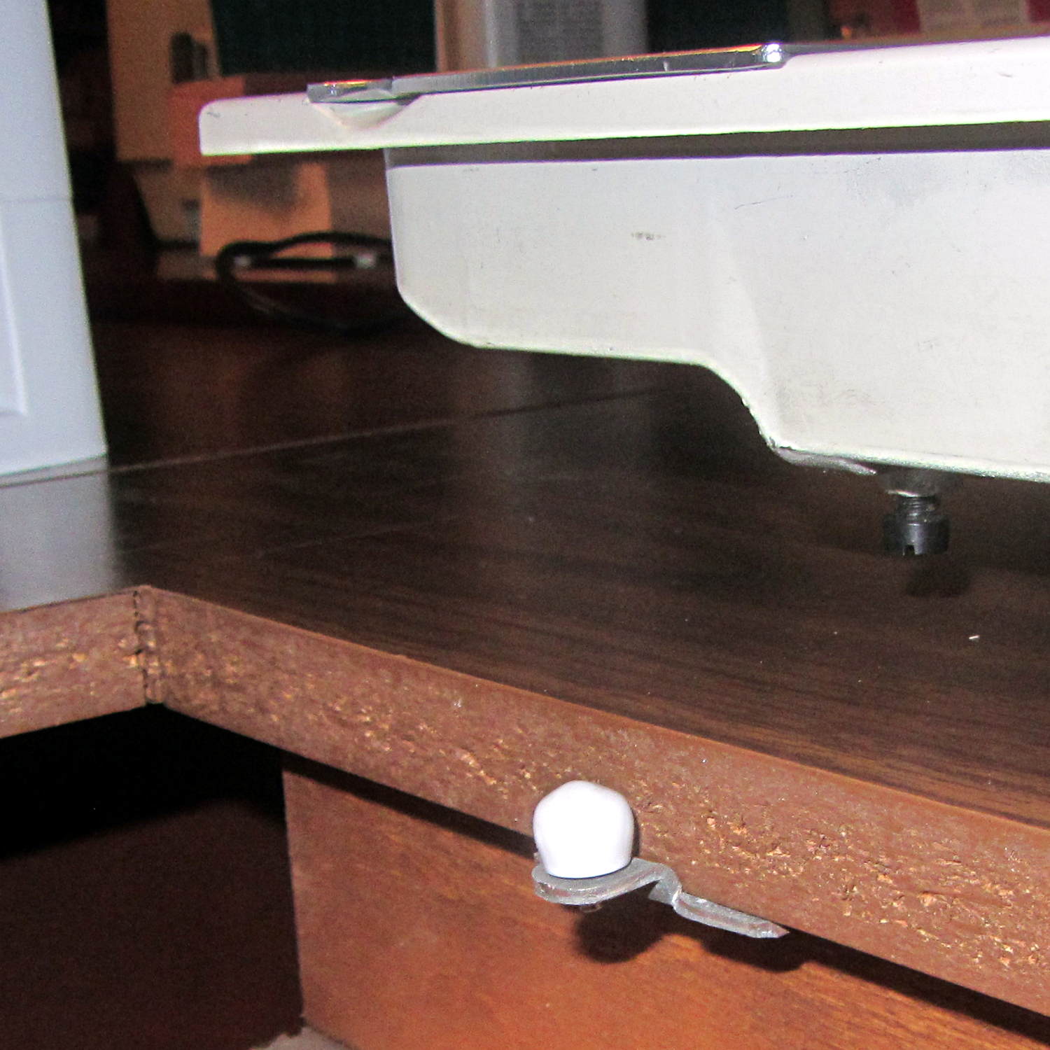
    Spun into their brackets, they look quite nice, not that anybody will ever see them:

    Sewing Machine Supports - installed
    Sewing Machine Supports – installed

    The new-to-us table replaces the incredible collection of junk previously supporting Machine #3. I tucked some plastic foam around the near and right edges to fill the small gaps and it fits well:

    Sewing Machine Supports - machine installed
    Sewing Machine Supports – machine installed

    Obviously, the foam will fall out whenever Mary lifts the machine to tinker with machinery under the platform, so we’ll see how often pins & needles slip through the cracks without the foam.

    That machine awaits a lighting update, because I’m awaiting some rectangular chip-on-board LED strips from halfway around the planet.

    Early reports concerning the sewing table seem promising…

  • Sears Sewing Table Hinge Covers

    The extension surfaces on the Sears sewing table in the Basement Sewing Room unfold from the top, leaving the hinges exposed:

    Sears Sewing Table - hinge
    Sears Sewing Table – hinge

    Alas, quilts snag on the squared-off ends of the hinges, a situation that is not to be tolerated…

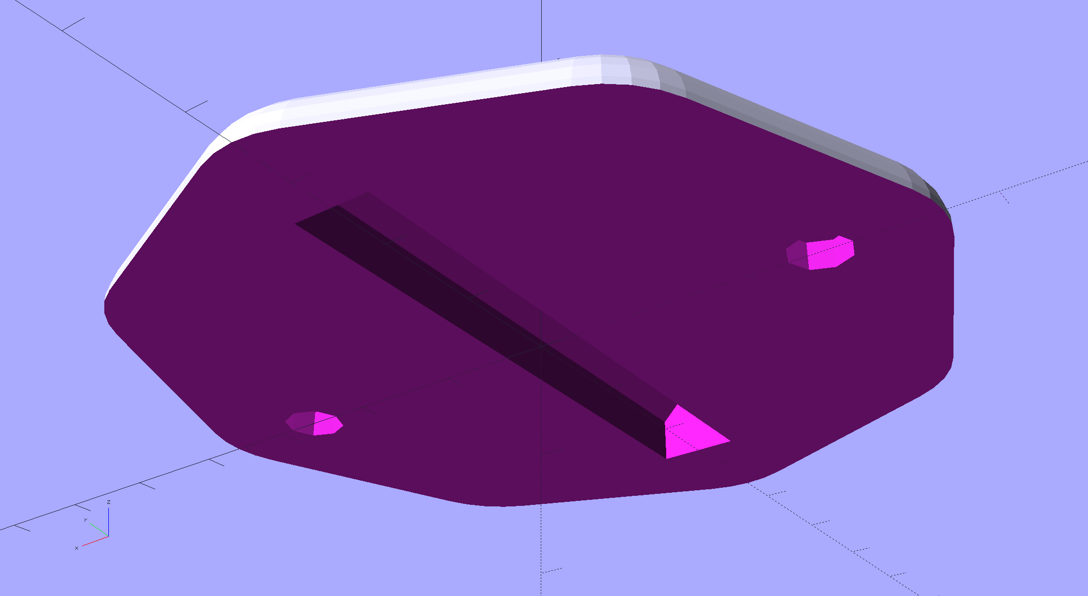
    This protective cap isn’t as small as we’d like, but it must be that thick to cover the hinge, that long to cover the squared-off ends, and that wide for symmetry:

    Sears Sewing Table Hinge Cover - solid model
    Sears Sewing Table Hinge Cover – solid model

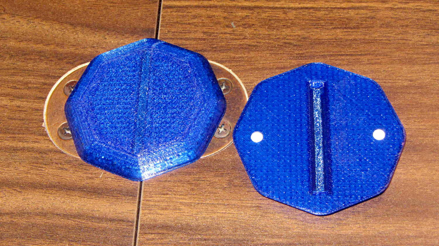
    Two neodymium magnets fit in the holes and secure the cover to the all-steel “bronzed” hinges:

    Sears Sewing Table - hinge covers
    Sears Sewing Table – hinge covers

    We’re not sure how well that will work in the long term, but early returns seem promising.

    It could be slightly narrower left-to-right and maybe fewer vertices should be oriented differently.

    The OpenSCAD source code as a GitHub gist:

    // Vacuum Tube LED Lights
    // Ed Nisley KE4ZNU January 2016
    //- Extrusion parameters must match reality!
    ThreadThick = 0.20;
    ThreadWidth = 0.40;
    HoleWindage = 0.2;
    Protrusion = 0.1; // make holes end cleanly
    inch = 25.4;
    function IntegerMultiple(Size,Unit) = Unit * ceil(Size / Unit);
    //———————-
    // Dimensions
    Hinge = [7.0,52.0,6.0];
    TopThick = 3*ThreadThick;
    PlateThick = Hinge[2] + TopThick;
    NumSides = 8*4;
    //———————-
    // Useful routines
    module PolyCyl(Dia,Height,ForceSides=0) { // based on nophead's polyholes
    Sides = (ForceSides != 0) ? ForceSides : (ceil(Dia) + 2);
    FixDia = Dia / cos(180/Sides);
    cylinder(r=(FixDia + HoleWindage)/2,h=Height,$fn=Sides);
    }
    //———————-
    // Build it
    difference() {
    hull()
    for (a=[0:7])
    rotate(a*360/8)
    translate([Hinge[1]/2,0,0])
    scale([1.5,1.5,1])
    sphere(r=PlateThick,$fn=NumSides);
    hull()
    for (k=[-1,1])
    translate([0,Hinge[1]/2,k*(Hinge[2] – Hinge[0]/2)])
    rotate([90,0,0]) rotate(180/8)
    PolyCyl(Hinge[0],Hinge[1],8);
    for (i=[-1,1])
    translate([i*Hinge[1]/2,0,-Protrusion])
    PolyCyl(4.8,2.5 + Protrusion,8);
    translate([0,0,-PlateThick])
    cube(2*[Hinge[1],Hinge[1],PlateThick],center=true);
    }
  • Darning Foot Modification

    Mary wanted an opening in the front of the Darning Foot I didn’t modify the last time around, so I grabbed it in a machinist’s vise, grabbed that in the bench vise, and freehanded a Dremel slitting saw:

    Darning Foot - saw-cut foot
    Darning Foot – saw-cut foot

    A bit of file work and it looks pretty good, although neither of us like the blurred-from-the-factory red lines:

    Darning Foot - opened foot
    Darning Foot – opened foot

    This one retains the pin that lifts it as the needle rises, so it’s a hopping foot.

  • Olfa Rotary Cutter Spacer

    At some point along the way, the bright yellow washer (they call it a “spacer”) on Mary’s 60 mm Olfa rotary cutter went missing. A casual search suggests that replacement washers come directly from Olfa after navigating their phone tree, but …

    Judging from scuffs on the rear surface, the washer serves two purposes:

    • Hold the blade close to the handle against slightly misaligned cutting forces
    • Add more compression to the wave washer under the nut

    This model is much more intricate than the stock washer:

    Olfa Rotary Cutter - backing washer
    Olfa Rotary Cutter – backing washer

    The trench across the middle of the thicker part allows a wider compression adjustment range for the wave washer and provides more thread engagement at the lightest setting for my liking. The shape comes from the chord equation based on measurements of the wave washer:

    Olfa Rotary Cutter - washer doodles
    Olfa Rotary Cutter – washer doodles

    The wave washer keys on the bolt flats: the whole affair rotates with the blade and gives the nut no inclination to unscrew. If you remove the trench, the remaining hole has the proper shape to key on the bolt and rotate with it; with the trench in place, the wave washer’s sides haul the plastic washer along with it.

    The plain ring, just two threads thick, glues bottom-to-bottom on the thicker part to soak up the air gap and provide more blade stability. It’s not entirely clear that’s a win; it’s easy to omit.

    It looks about like you’d expect:

    Olfa Rotary Cutter - washer in place
    Olfa Rotary Cutter – washer in place

    The wave washer must go on the bolt with the smooth curve downward into the trench. That orientation that wasn’t enforced by the Official Olfa spacer washer’s smooth sides.

    The nut sits upside-down to show the face that normally sits against the wave washer. I’d lay long odds that the recess around the threads originally held a conical compression spring with a penchant for joining the dust bunnies under the sewing table. You can insert the wave washer the wrong way, but it doesn’t store enough energy to go airborne unless you drop it, which did happen once with the expected result.

    The OpenSCAD source code as a GitHub gist:

    // Olfa rotary cutter backing washer
    // Ed Nisley KE4ZNU January 2016
    Layout = "Build";
    //- Extrusion parameters must match reality!
    // Print with +1 shells and 3 solid layers
    ThreadThick = 0.20;
    ThreadWidth = 0.40;
    HoleWindage = 0.2;
    function IntegerMultiple(Size,Unit) = Unit * ceil(Size / Unit);
    Protrusion = 0.1; // make holes end cleanly
    //———————-
    // Dimensions
    WasherOD = 35.0;
    WasherThick = 1.5;
    WaveOD = 14.0; // wave washer flat dia
    WaveM = 1.8; // height of wave washer bend
    BendRad = (pow(WaveM,2) + pow(WaveOD,2)/4) / (2*WaveM); // radius of wave washer bend
    echo(str("Wave washer bend radius: ",BendRad));
    SpacerID = WaveOD + 2.0;
    SpacerThick = 2*ThreadThick;
    NumSides = 12*4;
    $fn = NumSides;
    //———————-
    // Useful routines
    module PolyCyl(Dia,Height,ForceSides=0) { // based on nophead's polyholes
    Sides = (ForceSides != 0) ? ForceSides : (ceil(Dia) + 2);
    FixDia = Dia / cos(180/Sides);
    cylinder(r=(FixDia + HoleWindage)/2,
    h=Height,
    $fn=Sides);
    }
    //———————-
    // Parts
    module Upper() {
    difference() {
    cylinder(d1=WasherOD,d2=(WasherOD – 2.0),h=WasherThick);
    translate([0,0,-Protrusion])
    intersection() {
    PolyCyl(8.2,2.0,8);
    cube([(6.0 + HoleWindage),10,2*WasherThick],center=true);
    }
    translate([-(WaveOD + 1.0)/2,0,BendRad])
    rotate([0,90,0]) rotate(0*180/16)
    PolyCyl(BendRad*2,(WaveOD + 1),16);
    }
    }
    module Spacer() {
    difference() {
    cylinder(d=WasherOD,h=SpacerThick);
    translate([0,0,-Protrusion])
    cylinder(d=SpacerID,h=2*SpacerThick);
    }
    }
    //———————-
    // Build it!
    if (Layout == "Show") {
    translate([0,0,SpacerThick])
    color("Cyan")
    Upper();
    color("LightCyan")
    Spacer();
    }
    if (Layout == "Build") {
    translate([-0.6*WasherOD,0,0])
    Upper();
    translate([0.6*WasherOD,0,0])
    Spacer();
    }