The Smell of Molten Projects in the Morning

Ed Nisley's Blog: Shop notes, electronics, firmware, machinery, 3D printing, laser cuttery, and curiosities. Contents: 100% human thinking, 0% AI slop.

Tag: RPi

Raspberry Pi

  • Raspberry Pi HQ Camera Mount

    Raspberry Pi HQ Camera Mount

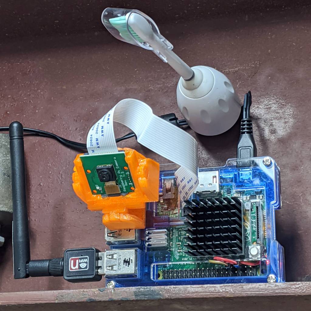
    As far as I can tell, Raspberry Pi cases are a solved problem, so 3D printing an intricate widget to stick a Pi on the back of an HQ camera seems unnecessary unless you really, really like solid modeling, which, admittedly, can be a thing. All you really need is a simple adapter between the camera PCB and the case of your choice:

    HQ Camera Backplate - OpenSCAD model
    HQ Camera Backplate – OpenSCAD model

    A quartet of 6 mm M2.5 nylon spacers mount the adapter to the camera PCB:

    RPi HQ Camera - nylon standoffs
    RPi HQ Camera – nylon standoffs

    The plate has recesses to put the screw heads below the surface. I used nylon screws, but it doesn’t really matter.

    The case has all the right openings, slots in the bottom for a pair of screws, and costs six bucks. A pair of M3 brass inserts epoxied into the plate capture the screws:

    RPi HQ Camera - case adapter plate - screws
    RPi HQ Camera – case adapter plate – screws

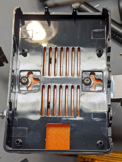
    Thick washers punched from an old credit card go under the screws to compensate for the case’s silicone bump feet. I suppose Doing the Right Thing would involve 3D printed spacers matching the cross-shaped case cutouts.

    Not everyone agrees with my choice of retina-burn orange PETG:

    RPi HQ Camera - 16 mm lens - case adapter plate
    RPi HQ Camera – 16 mm lens – case adapter plate

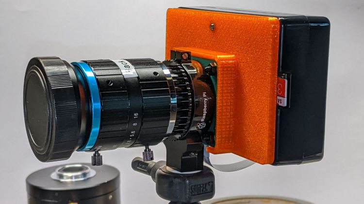
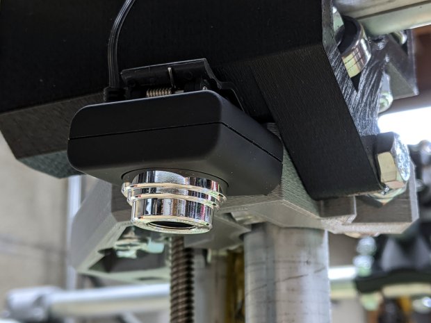
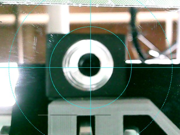
    Yes, that’s a C-mount TV lens lurking in the background, about which more later.

    The OpenSCAD source code as a GitHub Gist:

    // Raspberry Pi HQ Camera Backplate
    // Ed Nisley KE4ZNU 2020-09
    //– Extrusion parameters
    /* [Hidden] */
    ThreadThick = 0.25;
    ThreadWidth = 0.40;
    HoleWindage = 0.2;
    function IntegerMultiple(Size,Unit) = Unit * ceil(Size / Unit);
    function IntegerLessMultiple(Size,Unit) = Unit * floor(Size / Unit);
    Protrusion = 0.1; // make holes end cleanly
    inch = 25.4;
    ID = 0;
    OD = 1;
    LENGTH = 2;
    //- Basic dimensions
    CamPCB = [39.0,39.0,1.5]; // Overall PCB size, plus a bit
    CornerRound = 3.0; // … has rounded corners
    CamScrewOC = [30.0,30.0,0]; // … mounting screw layout
    CamScrew = [2.5,5.0,2.2]; // … LENGTH = head thickness
    Standoff = [2.5,5.5,6.0]; // nylon standoffs
    Insert = [3.0,4.0,4.0];
    WallThick = IntegerMultiple(2.0,ThreadWidth);
    PlateThick = Insert[LENGTH];
    CamBox = [CamPCB.x + 2*WallThick,
    CamPCB.y + 2*WallThick,
    Standoff.z + PlateThick + CamPCB.z + 1.0];
    PiPlate = [90.0,60.0,PlateThick];
    PiPlateOffset = [0.0,(PiPlate.y – CamBox.y)/2,0];
    PiSlotOC = [0.0,40.0];
    PiSlotOffset = [3.5,3.5];
    NumSides = 2*3*4;
    TextDepth = 2*ThreadThick;
    //———————-
    // Useful routines
    module PolyCyl(Dia,Height,ForceSides=0) { // based on nophead's polyholes
    Sides = (ForceSides != 0) ? ForceSides : (ceil(Dia) + 2);
    FixDia = Dia / cos(180/Sides);
    cylinder(r=(FixDia + HoleWindage)/2,h=Height,$fn=Sides);
    }
    //———————-
    // Build it
    difference() {
    union() {
    hull() // camera enclosure
    for (i=[-1,1], j=[-1,1])
    translate([i*(CamBox.x/2 – CornerRound),j*(CamBox.y/2 – CornerRound),0])
    cylinder(r=CornerRound,h=CamBox.z,$fn=NumSides);
    translate(PiPlateOffset)
    hull()
    for (i=[-1,1], j=[-1,1]) // Pi case plate
    translate([i*(PiPlate.x/2 – CornerRound),j*(PiPlate.y/2 – CornerRound),0])
    cylinder(r=CornerRound,h=PiPlate.z,$fn=NumSides);
    }
    hull() // camera PCB space
    for (i=[-1,1], j=[-1,1])
    translate([i*(CamPCB.x/2 – CornerRound),j*(CamPCB.y/2 – CornerRound),PlateThick])
    cylinder(r=CornerRound,h=CamBox.z,$fn=NumSides);
    translate([0,-CamBox.y/2,PlateThick + CamBox.z/2])
    cube([CamScrewOC.x – Standoff[OD],CamBox.y,CamBox.z],center=true);
    for (i=[-1,1], j=[-1,1]) // camera screws with head recesses
    translate([i*CamScrewOC.x/2,j*CamScrewOC.y/2,-Protrusion]) {
    PolyCyl(CamScrew[ID],2*CamBox.z,6);
    PolyCyl(CamScrew[OD],CamScrew[LENGTH] + Protrusion,6);
    }
    for (j=[-1,1]) // Pi case screw inserts
    translate([0,j*PiSlotOC.y/2 + PiSlotOffset.y,-Protrusion] + PiPlateOffset)
    PolyCyl(Insert[OD],2*PiPlate.z,6);
    translate([-PiPlate.x/2 + (PiPlate.x – CamBox.x)/4,0,PlateThick – TextDepth/2] + PiPlateOffset)
    cube([15.0,30.0,TextDepth + Protrusion],center=true);
    }
    translate([-PiPlate.x/2 + (PiPlate.x – CamBox.x)/4 + 3,0,PlateThick – TextDepth – Protrusion] + PiPlateOffset)
    linear_extrude(height=TextDepth + Protrusion,convexity=2)
    rotate(-90)
    text("Ed Nisley",font="Arial:style=Bold",halign="center",valign="center",size=4,spacing=1.05);
    translate([-PiPlate.x/2 + (PiPlate.x – CamBox.x)/4 – 3,0,PlateThick – TextDepth – Protrusion] + PiPlateOffset)
    linear_extrude(height=TextDepth + Protrusion,convexity=2)
    rotate(-90)
    text("KE4ZNU",font="Arial:style=Bold",halign="center",valign="center",size=4,spacing=1.05);
  • Raspberry Pi Streaming Video Loopback

    Raspberry Pi Streaming Video Loopback

    As part of spiffing my video presence for SquidWrench Zoom meetings, I put a knockoff RPi V1 camera into an Az-El mount, stuck it to a Raspberry Pi, installed the latest OS Formerly Known as Raspbian, did a little setup, and perched it on the I-beam over the workbench:

    Raspberry Pi - workbench camera setup
    Raspberry Pi – workbench camera setup

    The toothbrush head has a convenient pair of neodymium magnets affixing the RPi’s power cable to the beam, thereby preventing the whole lashup from falling off. The Pi, being an old Model B V 1.1, lacks onboard WiFi and requires a USB WiFi dongle. The white button at the lower right of the heatsink properly shuts the OS down and starts it up again.

    Zoom can show video only from video devices / cameras attached to the laptop, so the trick is to make video from the RPi look like it’s coming from a local laptop device.

    Start by exporting video from the Raspberry Pi:

    raspivid --nopreview -t 0 -rot 180 -awb sun --sharpness -50 --flicker 60hz -w 1920 -h 1080 -ae 48 -a 1032 -a 'RPi Cam1 %Y-%m-%d %X'  -b 1000000 -l -o tcp://0.0.0.0:5000

    The -rot 180 -awb sun --sharpness -50 --flicker 60hz parameters make the picture look better. The bottom of the video image There is no way to predict which side of the video will be on the same side as the cable, if that’s any help figuring out which end is up, and the 6500 K LED tubes apparently fill the shop with “sun”.

    The -l parameter causes raspivid to wait until it gets an incoming tcp connection on port 5000 from any other IP address, whereupon it begins capturing video and sending it out.

    Then, on the laptop, create a V4L loopback device:

    sudo modprobe v4l2loopback devices=1 video_nr=10 exclusive_caps=1 card_label="Workbench"

    Zoom will then include a video source identified as “Workbench” in its list of cameras.

    Now fetch video from the RPi and ram it into the loopback device:

    ffmpeg -f h264 -i tcp://192.168.1.50:5000 -f v4l2 -pix_fmt yuv420p /dev/video10

    VLC knows it as /dev/video10:

    RPi - V4L loopback - screen grab
    RPi – V4L loopback – screen grab

    That’s the edge of the workbench over there on the left, looking distinctly like a cliff.

    The RPi will happily stream video all day long to ffmpeg while you start / stop the display program pulling the bits from the video device. However, killing ffmpeg also kills raspivid, requiring a manual restart of both programs. This isn’t a dealbreaker for my simple needs, but it makes unattended streaming from, say, a yard camera somewhat tricky.

    There appear to be an infinite number of variations on this theme, not all of which work, and some of which rest upon an unsteady ziggurat of sketchy / unmaintained software.

    Addendum: If you have a couple of RPi cameras, it’s handy to run the matching ssh and ffmpeg sessions in screen / tmux / whatever terminal multiplexer you prefer. I find it easier to flip through those sessions with Ctrl-A N, rather than manage half a dozen tabs in a single terminal window. Your mileage may differ.

  • PiHole with DNS-over-HTTP: Revised

    More than a year later, the PiHole continues to work fine, but the process for installing the Cloudflare DoH machinery has evolved.

    (And, yes, it’s supposed to be DNS-over-HTTPS. So it goes.)

    To forestall link rot, the key points:

    cd /tmp ;  wget https://bin.equinox.io/c/VdrWdbjqyF/cloudflared-stable-linux-arm.tgz
    tar -xvzf cloudflared-stable-linux-arm.tgz 
    sudo cp cloudflared /usr/local/bin
    sudo chmod +x /usr/local/bin/cloudflared
    sudo cloudflared -v
    sudo useradd -s /usr/sbin/nologin -r -M cloudflared
    sudo nano /etc/default/cloudflared
    ----
    CLOUDFLARED_OPTS=--port 5053 --upstream https://1.1.1.1/dns-query --upstream https://1.0.0.1/dns-query 
    ----
    sudo chown cloudflared:cloudflared /etc/default/cloudflared
    sudo chown cloudflared:cloudflared /usr/local/bin/cloudflared
    sudo nano /etc/systemd/system/cloudflared.service
    ----
    [Unit]
    Description=cloudflared DNS over HTTPS proxy
    After=syslog.target network-online.target
    
    [Service]
    Type=simple
    User=cloudflared
    EnvironmentFile=/etc/default/cloudflared
    ExecStart=/usr/local/bin/cloudflared proxy-dns $CLOUDFLARED_OPTS
    Restart=on-failure
    RestartSec=10
    KillMode=process
    
    [Install]
    WantedBy=multi-user.target
    ----
    sudo systemctl enable cloudflared
    sudo systemctl start cloudflared
    sudo systemctl status cloudflared

    Then aim PiHole’s DNS at 127.0.0.1#5053. It used to be on port #54, for whatever that’s worth.

    Verify it at https://1.1.1.1/help, which should tell you DoH is in full effect.

    To update the daemon, which I probably won’t remember:

    wget https://bin.equinox.io/c/VdrWdbjqyF/cloudflared-stable-linux-arm.tgz
    tar -xvzf cloudflared-stable-linux-arm.tgz
    sudo systemctl stop cloudflared
    sudo cp ./cloudflared /usr/local/bin
    sudo chmod +x /usr/local/bin/cloudflared
    sudo systemctl start cloudflared
    cloudflared -v
    sudo systemctl status cloudflared

    And then It Just Works … again!

  • MPCNC: bCNC Probe Camera Refresh

    For the usual inscrutable reasons, updating bCNC killed the USB camera on the MPCNC, although it still worked fine with VLC. Rather than argue with it, I popped a more recent camera from the heap and stuck it onto the MPCNC central assembly:

    bCNC - USB probe camera - attachment
    bCNC – USB probe camera – attachment

    This one has a nice rectangular case, although the surface might be horrible silicone that turns to snot after a few years. The fancy silver snout rotates to focus the lens from a few millimeters to infinity … and beyond!

    If you think it looks a bit off-kilter, you’re absolutely right:

    bCNC - USB probe camera - off-axis alignment
    bCNC – USB probe camera – off-axis alignment

    The lens image reflected in a mirror on the platform shows the optical axis has nothing whatsoever to do with the camera case or lens snout:

    bCNC - USB probe camera - off-axis reflection
    bCNC – USB probe camera – off-axis reflection

    Remember, the mirror reflects the lens image back to itself only when the optical axis is perpendicular to the mirror. With the mirror flat on the platform, the lens must be directly above it.

    Because the MPCNC camera rides at a constant height over the platform, the actual focus & scale depends on the material thickness, but this should be typical:

    bCNC - USB Probe Camera - scale - screenshot
    bCNC – USB Probe Camera – scale – screenshot

    It set up a Tek Circuit Computer test deck within 0.2 mm and the other two within 0.1 mm, so it’s close enough.

    The image looks a whole lot better: cheap USB cameras just keep improving …

  • Raspberry Pi Shutdown / Start Button

    While adding the usual Reset button to a Raspberry Pi destined for a Show-n-Tell with the HP 7475A plotter, I browsed through the latest dtoverlay README and found this welcome surprise:

    Name:   gpio-shutdown
    Info:   Initiates a shutdown when GPIO pin changes. The given GPIO pin
            is configured as an input key that generates KEY_POWER events.
            This event is handled by systemd-logind by initiating a
            shutdown. Systemd versions older than 225 need an udev rule
            enable listening to the input device:
    
                    ACTION!="REMOVE", SUBSYSTEM=="input", KERNEL=="event*", \
                            SUBSYSTEMS=="platform", DRIVERS=="gpio-keys", \
                            ATTRS{keys}=="116", TAG+="power-switch"
    
            This overlay only handles shutdown. After shutdown, the system
            can be powered up again by driving GPIO3 low. The default
            configuration uses GPIO3 with a pullup, so if you connect a
            button between GPIO3 and GND (pin 5 and 6 on the 40-pin header),
            you get a shutdown and power-up button.
    Load:   dtoverlay=gpio-shutdown,<param>=<val>
    Params: gpio_pin                GPIO pin to trigger on (default 3)
    
            active_low              When this is 1 (active low), a falling
                                    edge generates a key down event and a
                                    rising edge generates a key up event.
                                    When this is 0 (active high), this is
                                    reversed. The default is 1 (active low).
    
            gpio_pull               Desired pull-up/down state (off, down, up)
                                    Default is "up".
    
                                    Note that the default pin (GPIO3) has an
                                    external pullup.
    
            debounce                Specify the debounce interval in milliseconds
                                    (default 100)

    So I added two lines to /boot/config.txt:

    dtoverlay=gpio-shutdown
    dtparam=act_led_trigger=heartbeat

    The fancy “Moster heatsink” case doesn’t leave much room for wiring:

    RPi Shutdown Restart Switch - GPIO 3
    RPi Shutdown Restart Switch – GPIO 3

    The switch button is slightly shorter than the acrylic sheet, so it’s recessed below the surface and requires a definite push to activate. It’s not as if it’ll get nudged by accident, but ya never know.

    I’ll eventually migrate this change to all the RPi boxes around the house, because it just makes more sense than any of the alternatives. Heck, it’ll free up a key on the streaming radio player keypads, although I must move the I²C display to Bus 0 to avoid contention on Pin 3.

    For reference, the Raspberry Pi header pinout:

    Raspberry Pi pinout
    Raspberry Pi pinout

    I don’t know if I²C Bus 0 has the same 1.8 kΩ pullups as Bus 1, though; a look at the bus currents will be in order.

  • HP 7475A Plotter Data Sniffing: socat Serial Port Tee

    Some hints and examples provided the socat incantation required to sniff serial data between my Superformula demo program (on the Raspberry Pi) and my HP 7475A plotter:

    socat /dev/ttyUSB0,raw,echo=0 SYSTEM:'tee /tmp/in.txt | socat - "PTY,link=/tmp/ttyv0,raw,echo=0,wait-slave" | tee /tmp/out.txt'

    The out.txt file collects data from the program to the plotter, the in.txt file holds data from the plotter to the program, and both files contain exactly and only the serial data, so some interpretation will be required.

    With that in hand, tweak the .chiplotle/config.py file to aim Chiplotle at the virtual serial port:

    serial_port_to_plotter_map = {'/tmp/ttyv0' : 'HP7475A'}

    This is dramatically easier than wiring a pair of additional hardware serial ports onto the RS-232 connection between the two:

    HP 7475A - serial port adapters - hardcore
    HP 7475A – serial port adapters – hardcore

    The adapter stack instantly become a custom cable, although I miss Der Blinkenlights.

    The HPGL output to the plotter (out.txt) comes from the Chiplotle driver with no embedded linefeed / carriage return characters, as HPGL uses semicolon command terminators, making it one humongous line impervious to the usual text utilities. In addition, several plotter configuration commands have prefix ESC (0x1b) characters without semicolon separators. Each LB (label) command within the stream ends with a 0x03 ETX character.

    While one could fix all those gotchas with a sufficiently complex sed script, I manually separated the few lines I needed after each semicolon, then converted the raw ASCII control characters to displayable Unicode glyphs (␛ and ␃), making it legible for a presentation:

    head -c 1000 out.txt
    ␛.B
    ␛.(;
    IN;
    OW;OW;OW;OW;
    ␛.H200:;
    SC;
    OW;OW;OW;OW;
    IP0,0,16640,10365;
    OW;OW;
    SC-8320,8320,-5182,5182;
    SI0.13,0.17;
    VS8;
    PA5320,-4282;
    SP1;
    PA5320,-4282;
    LBStarted 2020-01-09 18:03:57.494617␃;
    SP1;
    PA5320,-4382;
    LBPen 1: ␃;
    SP1;
    LBm=1.9 n1=0.71 n2=n3=0.26␃;
    SP1;
    PU;
    PA8320.00,0.00;
    PD;
    PA8320.00,0.00,
    6283.71,24.59,
    5980.63,46.81,
    5789.79,67.98,
    5648.37,88.44,
    5535.22,108.34,
    5440.50,127.81,
    5358.77,146.89,
    <<< snippage >>>

    The corresponding responses from the plotter to the program (in.txt) are separated by carriage return characters (␍) with no linefeeds (␊), so the entire file piles up at the terminal’s left margin when displayed with the usual text tools. Again, manually splitting the output at the end of each line produces something useful:

    1024
    0,0,16640,10365
    0,0,16640,10365
    0,0,16640,10365
    0,0,16640,10365
    0,0,16640,10365
    0,0,16640,10365
    0,0,16640,10365
    0,0,16640,10365
    0,0,16640,10365
    0,0,16640,10365
    26
    18
    18
    <<< snippage >>>

    The first number gives the size of the serial FIFO buffer. An inexplicable ten OW; commands from deep in the Chiplotle driver code return the Output Window size in plotter units. No other commands produce any output until the plot finishes, whereupon my code waits for a digitized point from the plotter, with the (decimal) 18 indicating a point isn’t ready.

    All that at 9600 bits per second …

  • Raspberry Pi: Adding a PIXEL Desktop Launcher

    The Raspberry Pi’s Raspbian PIXEL Desktop UI (not to be confused with the Google Pixel phone) descends from LXDE, with all the advantages & disadvantages that entails. One nuisance seems to be the inability to create a launcher for a non-standard program.

    The stock task bar (or whatever it’s called) has a few useful launchers and you can add a launcher for a program installed through the usual Add/Remove Software function, as shown by the VLC icon:

    LXDE launcher icons
    LXDE launcher icons

    Adding a bCNC launcher requires a bit of legerdemain, because it’s not found in the RPi repositories. Instead, install bCNC according to its directions:

    … install various pre-requisites as needed …
    pip2 install --upgrade git+https://github.com/vlachoudis/bCNC 

    Which is also how you upgrade to the latest & greatest version, as needed.

    You then launch bCNC from inside a terminal:

    python2 -m bCNC

    The installation includes all the bits & pieces required to create a launcher; they’re just not in the right places.

    So put them there:

    sudo cp ./.local/lib/python2.7/site-packages/bCNC/bCNC.png /usr/share/icons/
    sudo cp .local/lib/python2.7/site-packages/bCNC/bCNC.desktop /usr/share/applications/bCNC.desktop

    The bCNC.desktop file looks like this:

    [Desktop Entry]
    Version=1.0
    Type=Application
    Name=bCNC
    Comment=bCNC Controller
    Exec=bCNC
    Icon=bCNC.png
    Path=
    Terminal=true
    StartupNotify=false
    Name[en_US]=bCNC

    Set Terminal=false if you don’t want a separate terminal window and don’t care about any of the messages bCNC writes to the console during its execution. However, those messages may provide the only hint about happened as bCNC falls off the rails.

    With all that in place, it turns out LXDE creates a user-specific panel configuration file only when you change the default system panel configuration. Add a VLC launcher to create the local ~/.config/lxpanel/LXDE-pi/panels/panel file.

    With that ball rolled, then add the bCNC launcher:

    nano .config/lxpanel/LXDE-pi/panels/panel
    … add this stanza …
    Plugin {
      type=launchbar
      Config {
        Button {
          id=bCNC.desktop
        }
      }
    }

    Log out, log back in again, and the bCNC icon should appear:

    LXDE launcher icons - additions
    LXDE launcher icons – additions

    Click it and away you go:

    bCNC - Running from LXDE Launcher
    bCNC – Running from LXDE Launcher

    At least you (and I) will start closer to the goal when something else changes …