Mashing rotary encoder reading together with the focus-distance-to-DAC equation produces well-behaved camera focusing.
First, set up another test range:
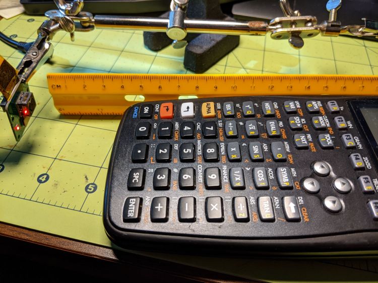
Run the test code:
# Simpleminded focusing test for
# Arducam Motorized Focus Camera
# Gets events through evdev from rotary encoder knob
# Ed Nisley - KE4ZNU
# 2020-10-20
import sys
import math
import evdev
import smbus
# useful functions
def DAC_from_distance(dist):
return math.trunc(256*(10.8 + 2180/dist))
# write DAC word to camera I2C bus device
# and ignore the omnipresent error return
def write_lens_DAC(bus,addr,val):
done = False
while not done:
try:
bus.write_word_data(addr,val >> 8,val & 0xff)
except OSError as e:
if e.errno == 121:
# print('OS remote error ignored')
done = True
except:
print(sys.exc_info()[0],sys.exc_info()[1])
else:
print('Write with no error!')
done = True
# set up focus distances
closest = 50 # mm
farthest = 500
nominal = 100 # default focus distance
foci = [n for n in range(closest,nominal,5)] \
+ [n for n in range(nominal,250,10)] \
+ [n for n in range(250,1501,25)]
# compute DAC equivalents for each distance
foci_DAC = list(map(DAC_from_distance,foci))
focus_index = foci.index(nominal)
# set up the I2C bus
f = smbus.SMBus(0)
lens = 0x0c
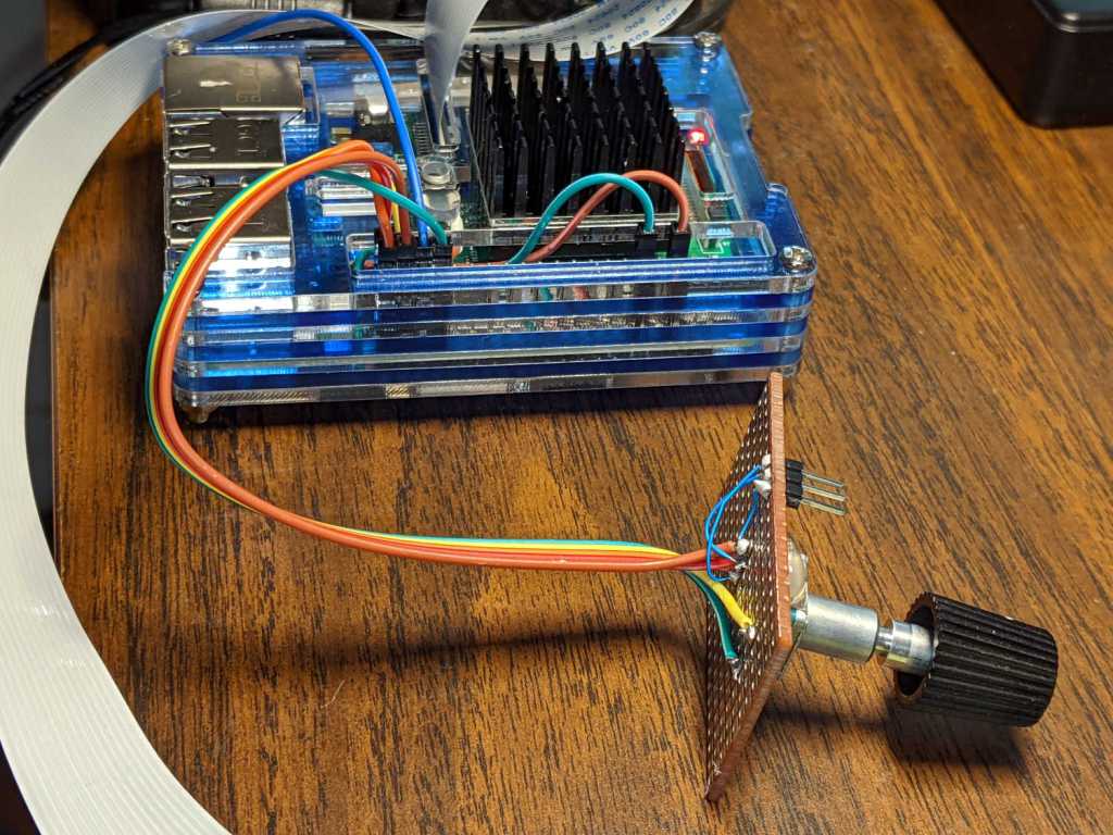
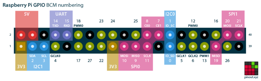
# set up the encoder device handler
# requires rotary-encoder dtoverlay aimed at pins 20 & 21
d = evdev.InputDevice('/dev/input/by-path/platform-rotary@14-event')
print('Rotary encoder device: {}'.format(d.name))
# set initial focus
write_lens_DAC(f,lens,foci_DAC[focus_index])
# fetch I2C events and update the focus forever
for e in d.read_loop():
# print('Event: {}'.format(e))
if e.type == evdev.ecodes.EV_REL:
# print('Rel: {}'.format(e.value))
if (e.value > 0 and focus_index < len(foci) - 1) or (e.value < 0 and focus_index > 0):
focus_index += e.value
dist = foci[focus_index]
dac = foci_DAC[focus_index]
print('Distance: {:4d} mm DAC: {:5d} {:04x} i: {:3d}'.format(dist,dac,dac,focus_index))
write_lens_DAC(f,lens,dac)
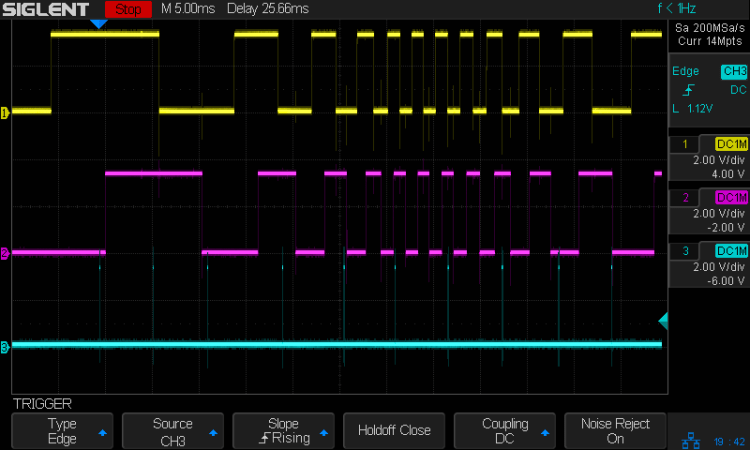
Because the knob produces increments of ±1, the code accumulates them into an index for the foci & foci_DAC lists, then sends the corresponding entry from the latter to the lens on every rotary encoder event.
And then It Just Works!
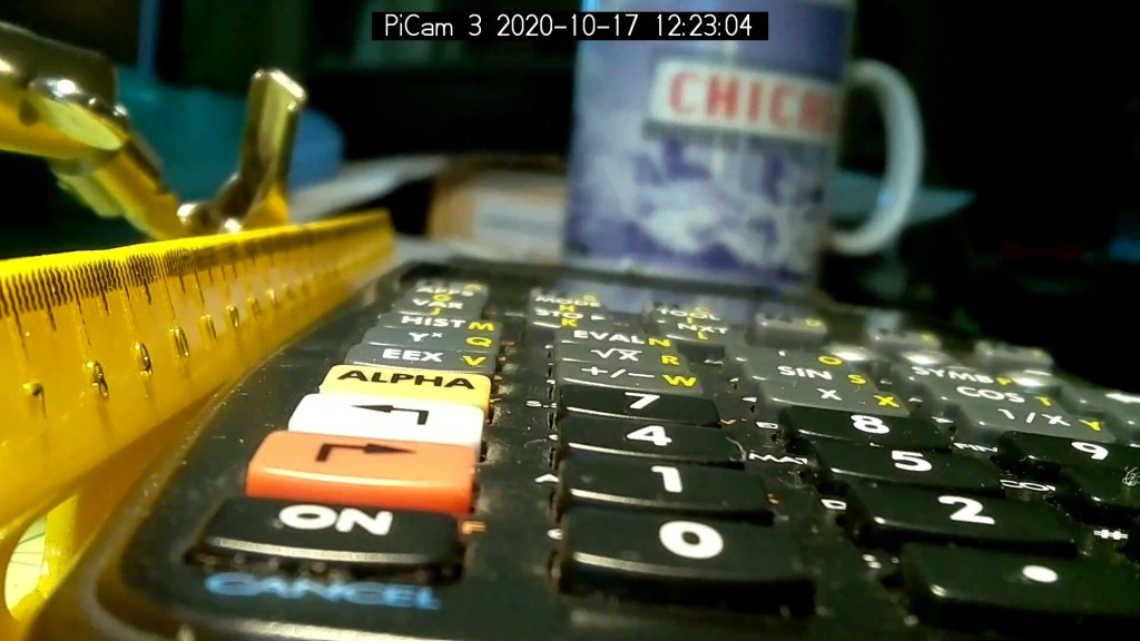
The camera powers up with the lens focused at infinity (or slightly beyond), but setting it to 100 mm seems more useful:

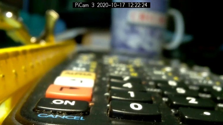
Turning the knob counterclockwise runs the focus inward to 50 mm:
Turning it clockwise cranks it outward to 1500 mm:
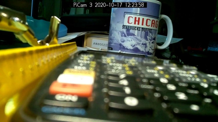
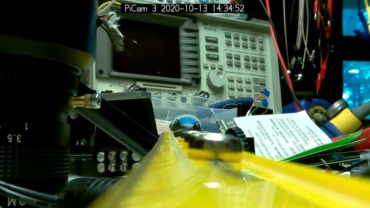
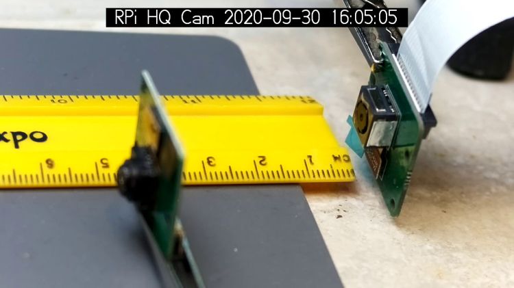
The mug is about 300 mm away, so the depth of field extends from there to infinity (and beyond).
It needs more work, but now it has excellent upside potential!