Ed Nisley's Blog: Shop notes, electronics, firmware, machinery, 3D printing, laser cuttery, and curiosities. Contents: 100% human thinking, 0% AI slop.
It turns out the thread guide on Mary’s new Juki TL-2010Q sewing machine has what’s euphemistcally known as “negative clearance” with the ruler foot she uses for quilting patterns. With the foot raised to move the cloth, inadvertently pressing the foot pedal or turning the handwheel can crunch the thread guide against the foot.
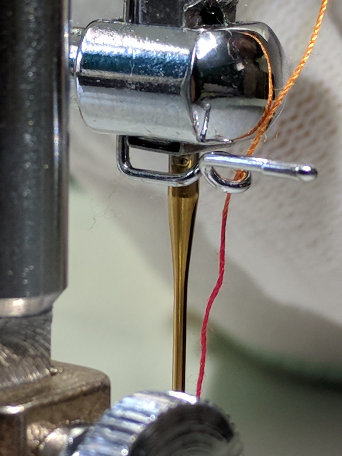
As you might expect, the intricately bent wire thread guide doesn’t survive the encounter. Not having a spare ready to hand and not knowing quite what it should look like, I reshaped it as best I could:
Juki thread guide – in vise
It worked moderately well:
Juki thread guide – reshaped installed
The automatic needle threader wasn’t reliable, but she could cope until the replacements arrived.
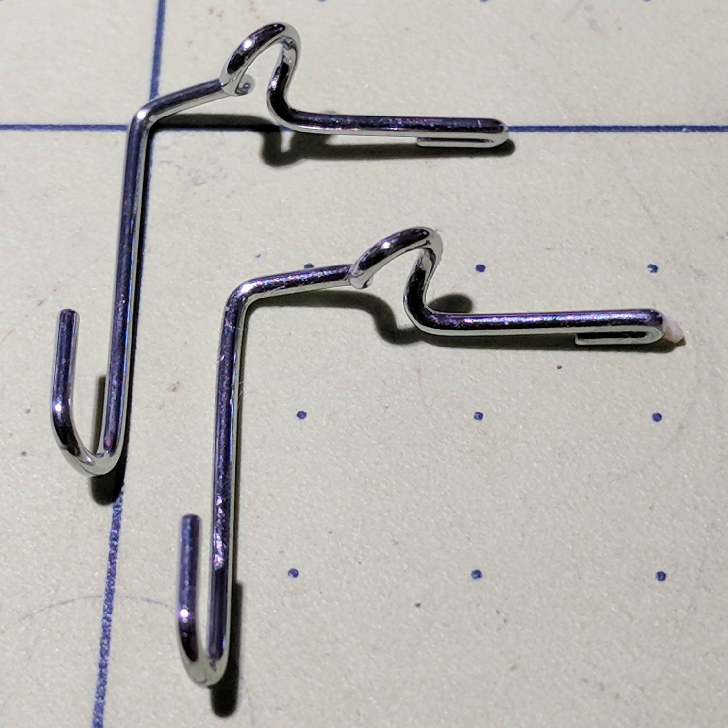
Comparing the new one (left) with the wrecked one (right) shows I didn’t re-bend the loop tightly enough, putting the end on the right at the wrong angle:
Juki thread guide – new vs reshaped
It’s the kind of shape you can duplicate by the thousands with a production machine, but can’t make at home without entirely too much tedious effort.
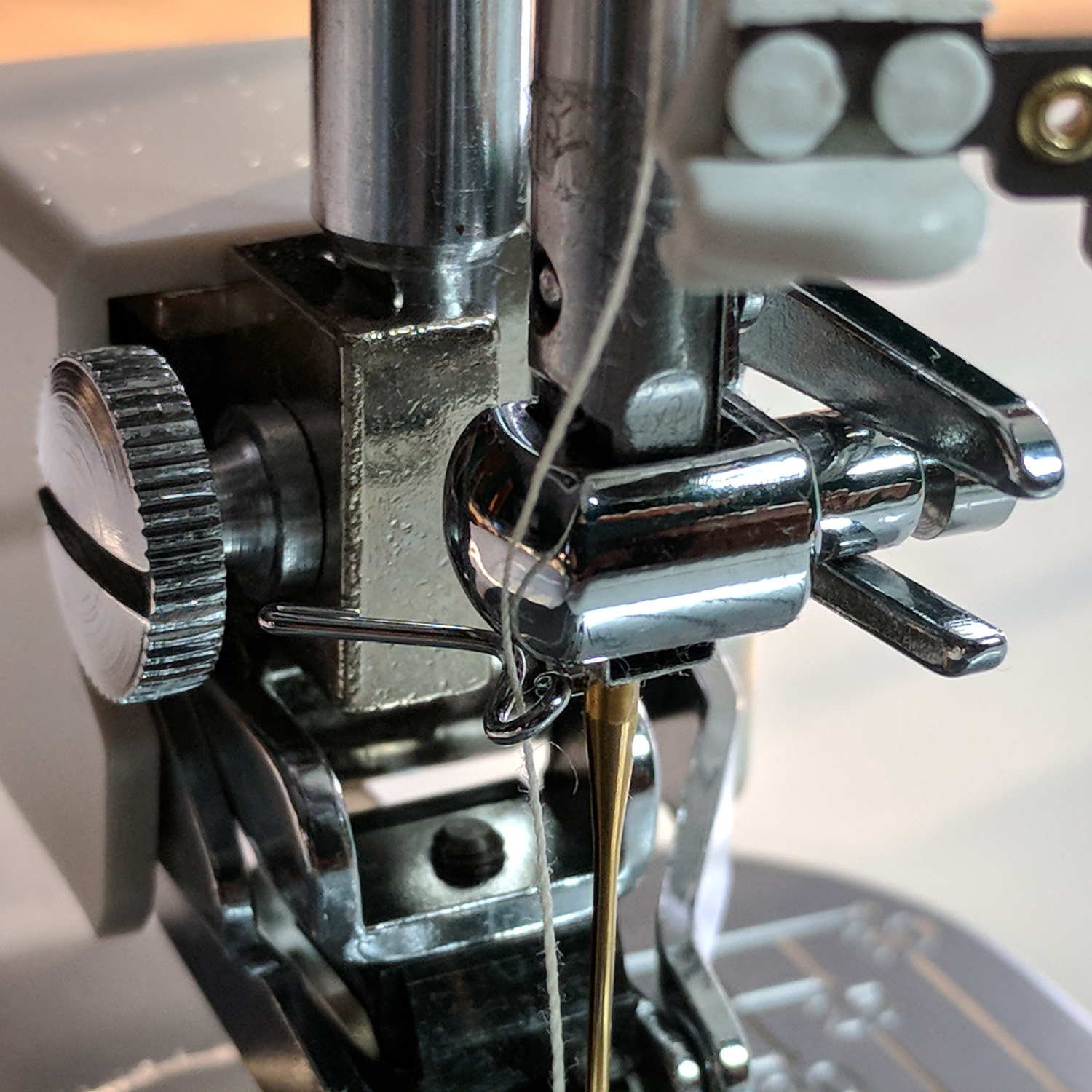
The new one works fine, seen here in front of a walking foot, with the auto-threader looming in the upper foreground:
It adds a festive touch when done up in orange PETG:
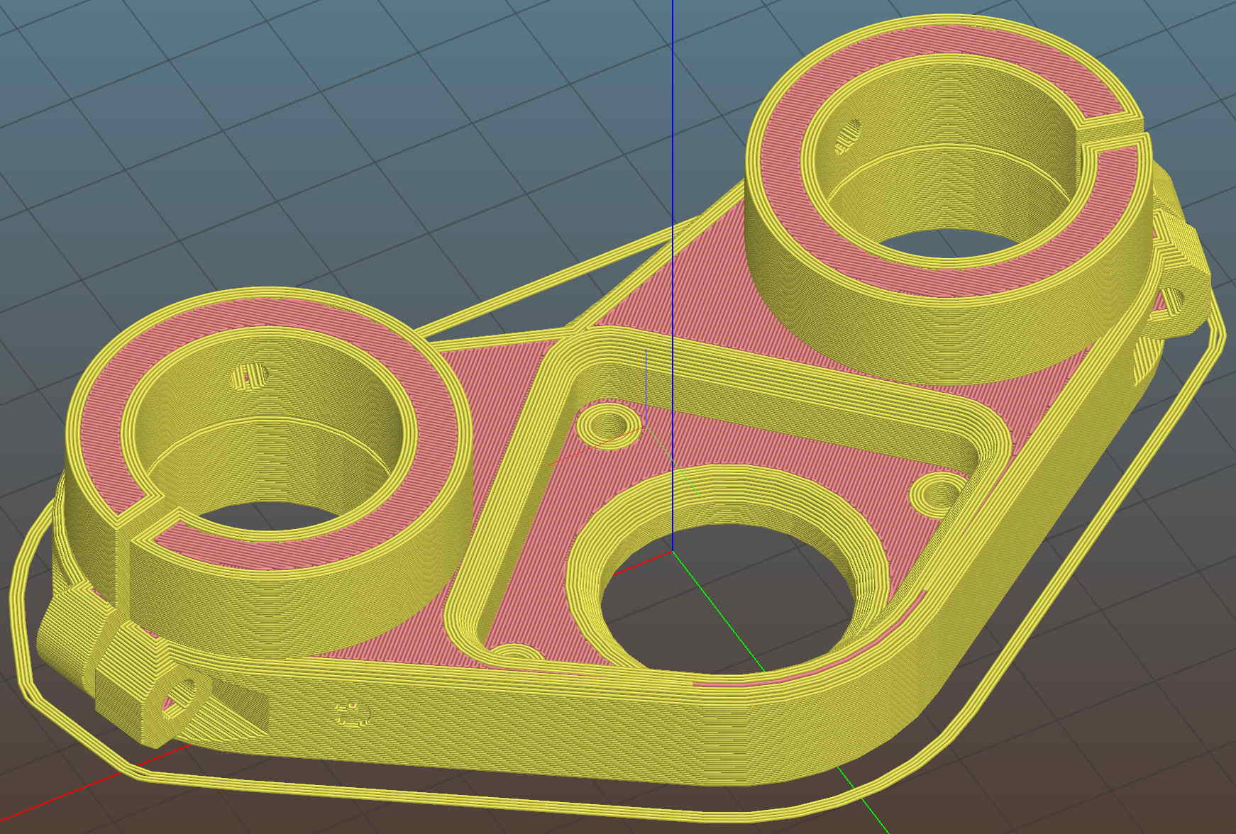
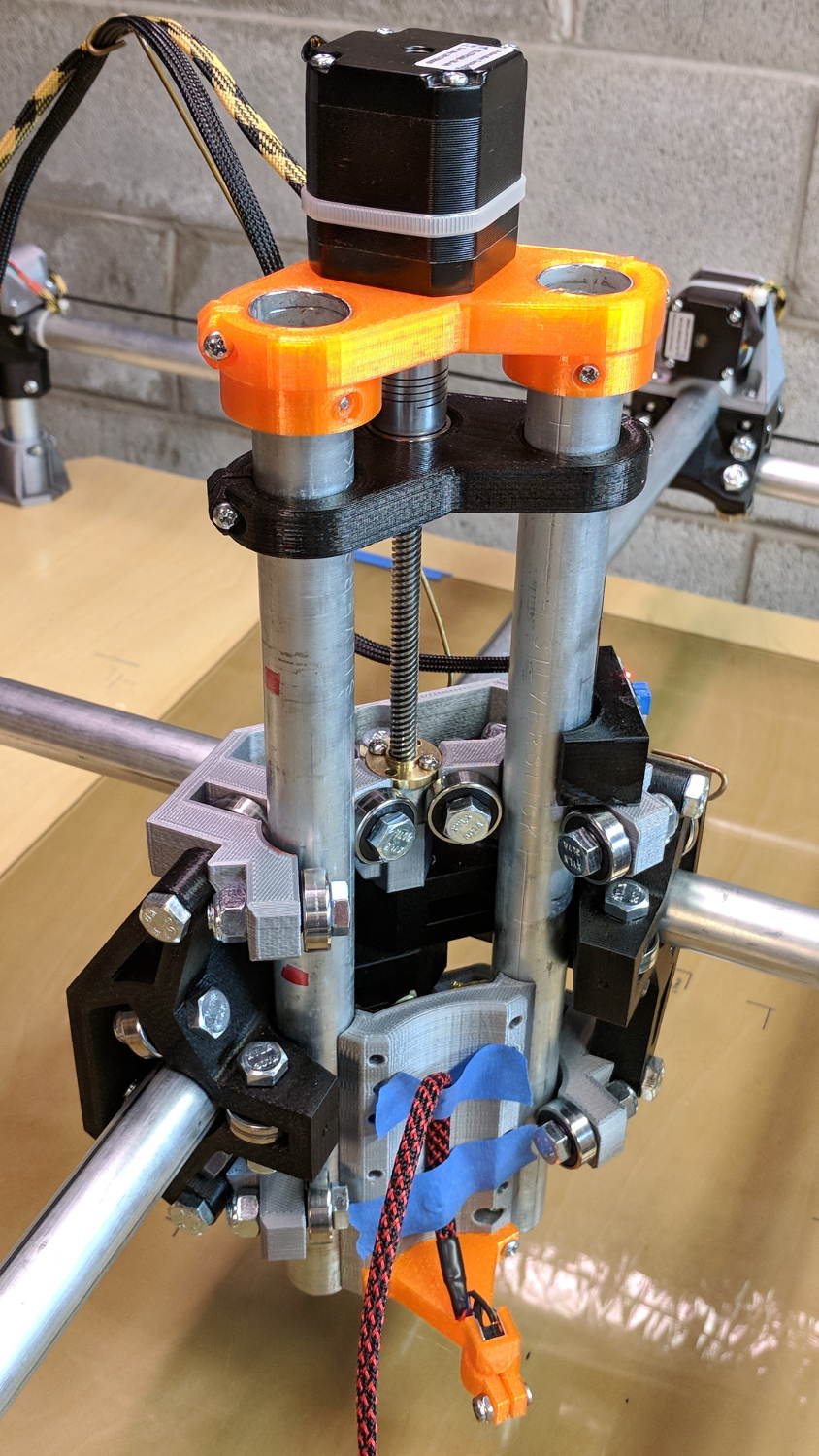
MPCNC – Reinforced Z Motor Mount
The attentive reader will note the missing head of the screw anchoring the mount to the left Z rail. Apparently a #32 drill was a bit too small to let the randomly chosen self-tapping screws thread themselves into EMT; they probably anchored a PCB to the plastic case of a long-forgotten lump of consumer electronics.
It should last long enough for something else to let go …
Two more umbrella struts snapped and required the same repair, but, having drained all the suitable snippets from the Box o’ Brass Cutoffs, some lathe work was in order:
Umbrella strut splint – cutting
I used the carbide insert in the mistaken belief it’d be less grabby, then applied the cutoff tool.
Break the edges, slide splints over the ribs, slobber epoxy on the struts, slide splints into place, apply masking tape for a bit of compression & alignment, and let it cure:
Our long-suffering and much-repairedKenmore clothes dryer didn’t shut off, with the heat on and the timer failing to advance from whatever position we set it to; the clothes were plenty dry and scorching hot. I tried “timed air dry” to eliminate the heater from the problem and found the timer still didn’t advance.
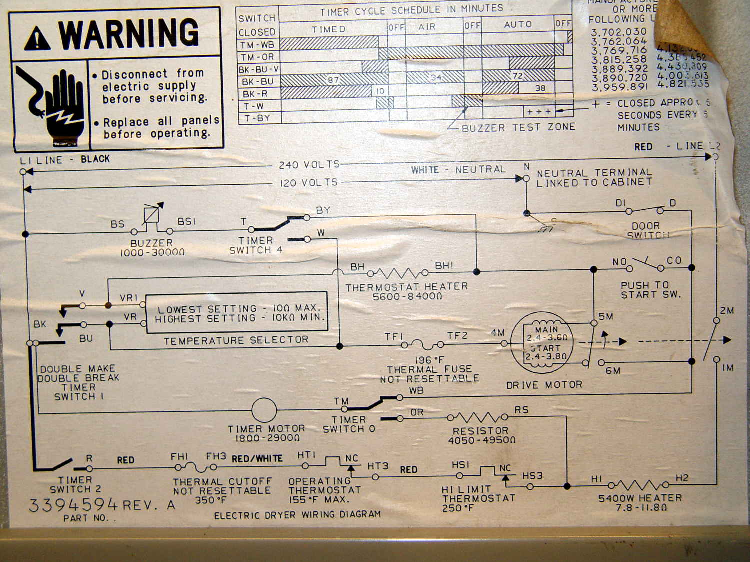
Referring to the wiring diagram may be of some help:
The timer motor is in the next-to-bottom ladder rung. Its BK terminal on the left connects to one side of the 240 VAC supply and the switch just to its right connects terminal TM to either the neutral AC line (thus unbalancing the 240 VAC line by a smidge) or to through a 4-ish kΩ resistor and the heater element (essentially zero, on this scale) to the other hot line; the resistor thus dropping 120-ish VAC.
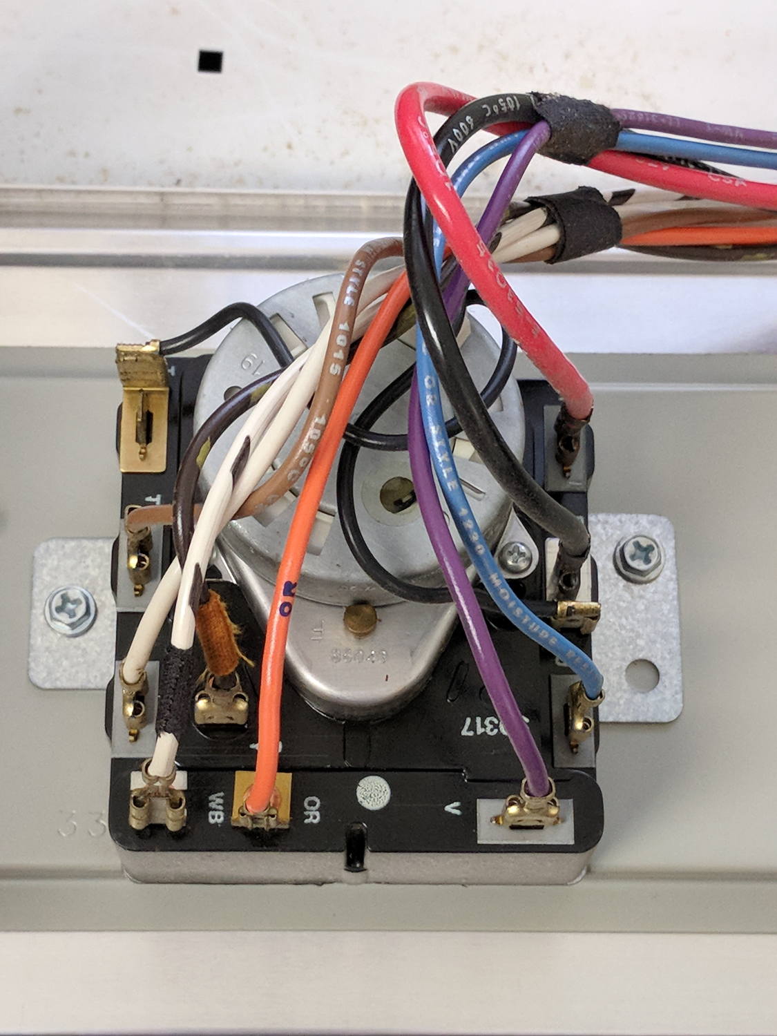
The various switches around the timer collect nearly all the wiring in the dryer:
Kenmore dryer – timer wiring
A closer look at the back, minus all the wiring:
Kenmore dryer – timer backplate
The motor comes off easily enough, revealing the fact that it’s not just an ordinary (i.e., cheap & readily available) timer motor:
Kenmore dryer – timer motor pinions
Hotwiring the motor through a widowmaker zip cord showed it worked just fine. For reference, the upper pinion rotates at about 45 sec/rev, the lower pinion takes maybe 1 hr/rev, both counterclockwise.
Reassembling and hotwiring the complete timer showed it worked just fine, too.
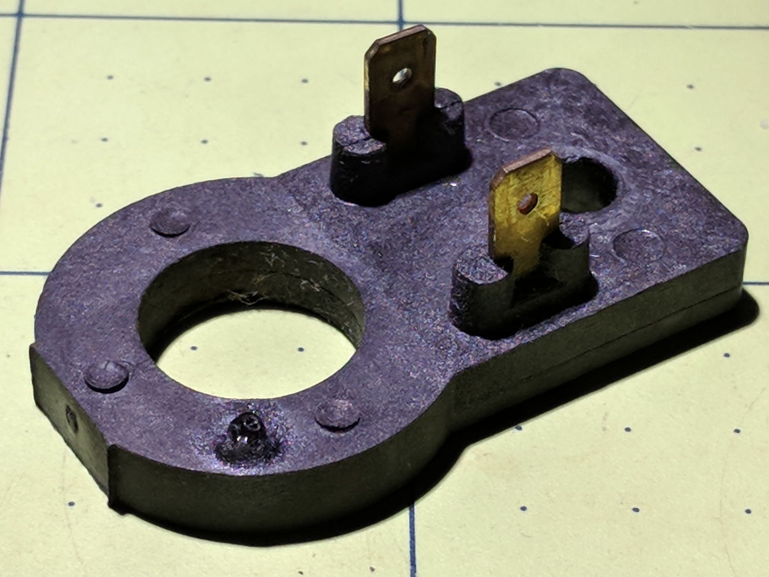
Poring over the wiring diagram suggested the power resistor might be open and, indeed, it was:
Kenmore dryer – power resistor failure
The raised zit near the front shouldn’t be there:
Kenmore dryer – power resistor failure – detail
Apparently, the resistive element broke at that spot, burned through the thermoset plastic case, and failed safe.
Introducing it to Mr Disk Sander revealed a cavity below the zit, surrounded by the remains of the resistive element:
Kenmore dryer – power resistor – cut open
You can get a replacement resistor from the usual suspects for prices between $20 and $40, plus or minus shipping, but their pictures look a lot like an ordinary power resistor inside a length of heatshrink tubing, rather than the molded OEM part. I don’t put much stock in reviews & comments, although they seemed to suggest you get, indeed, an ordinary power resistor.
I didn’t have a 4.7 kΩ power resistor in my (diminished) collection, so I soldered a giant 1.5 kΩ cylindrical resistor in series with a small 3.5 kΩ sandbox, wrapped them up, and tucked them under the front panel’s ground wire:
Kenmore dryer – expedient power resistor
A small box of resistors should arrive in the next month and I’ll re-do the repair with a bit more attention to permanency.
Three times is enemy action, but we’re not there yet. I was willing to believe something I’d done had killed both of the radios, even though it seemed unlikely for them to last five years and fail almost simultaneously.
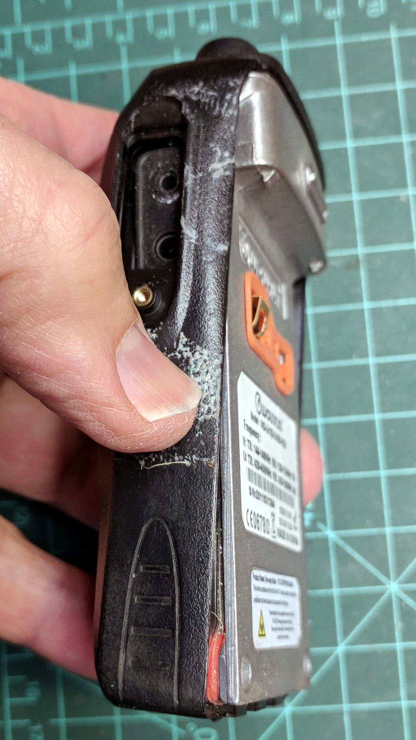
So I dismantled this one to see what’s inside. Pull off both knobs, remove the two screws at the bottom of the battery compartment, pry gently with a small screwdriver, and the whole PCB pulls out:
Wouxun KG-UV3D – disassembly
A bit more prying separates the big pieces:
Wouxun KG-UV3D – interior
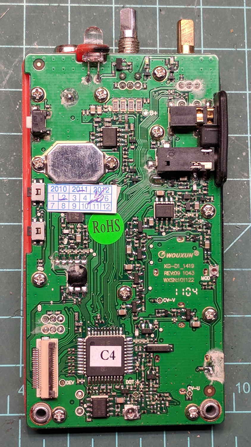
Looking closely at the main PCB showed some problems I definitely didn’t cause:
Wouxun KG-UV3D – PCB overview
Although it’s been riding around on my bike, the white blotches on the PCB came from inadequate flux removal after hand soldering.
A collection of images taken through the microscope reveals the problems:
This slideshow requires JavaScript.
I swabbed off the crud with denatured alcohol to no avail. The bottom side of the PCB has even more components and, I’m sure, even more crud, but I didn’t bother removing all the screws required to expose it, nor did I dismantle the other failed HT.
I doubt Wouxun’s QC improved over the last few years, which means the two replacement KG-UV3D radios I just bought are already on their last legs, despite my paying top dollar to the same reputable source that sold me the first pair.
We’ll be ready for new radios on new bikes by the time these fail.
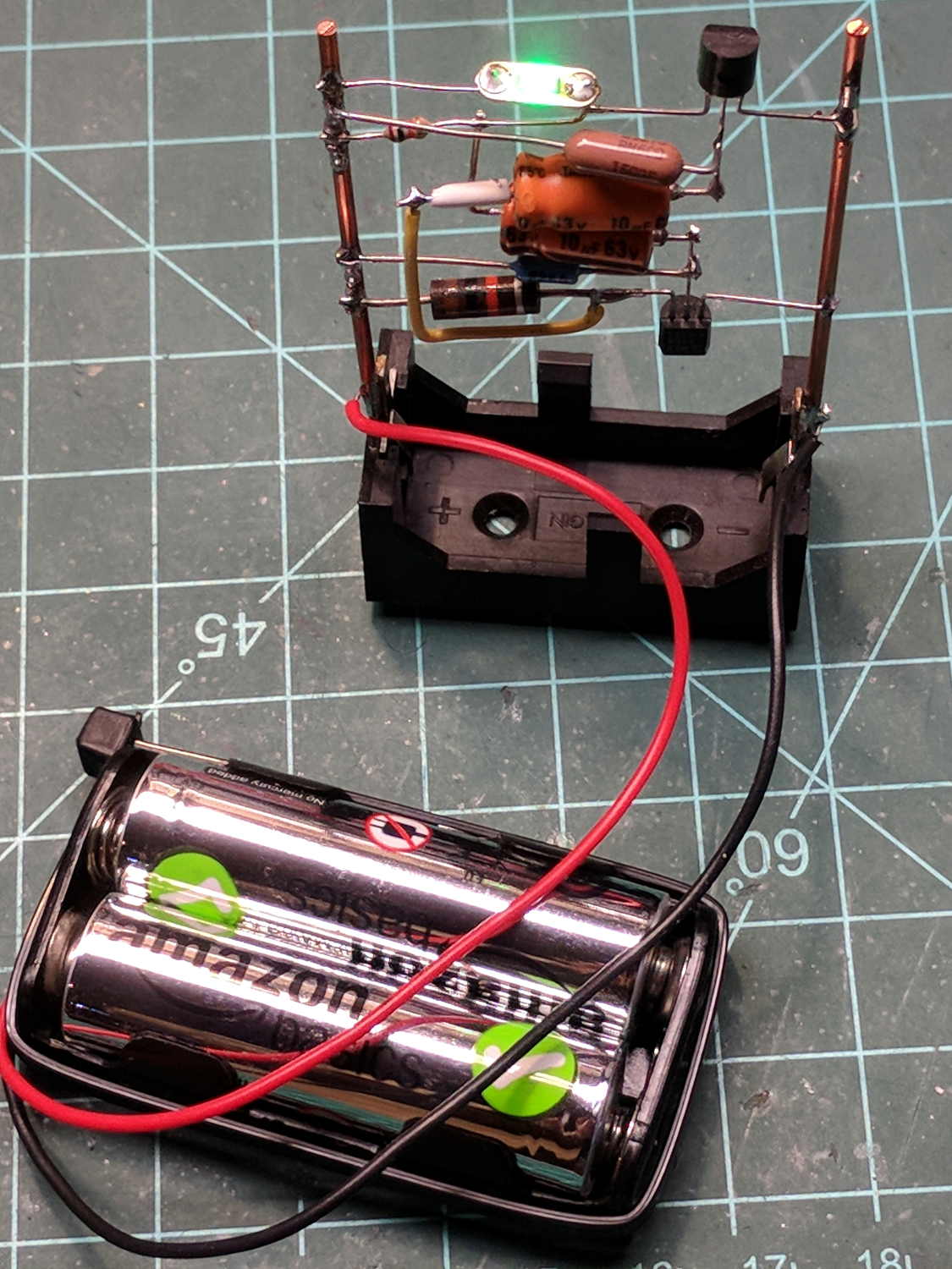
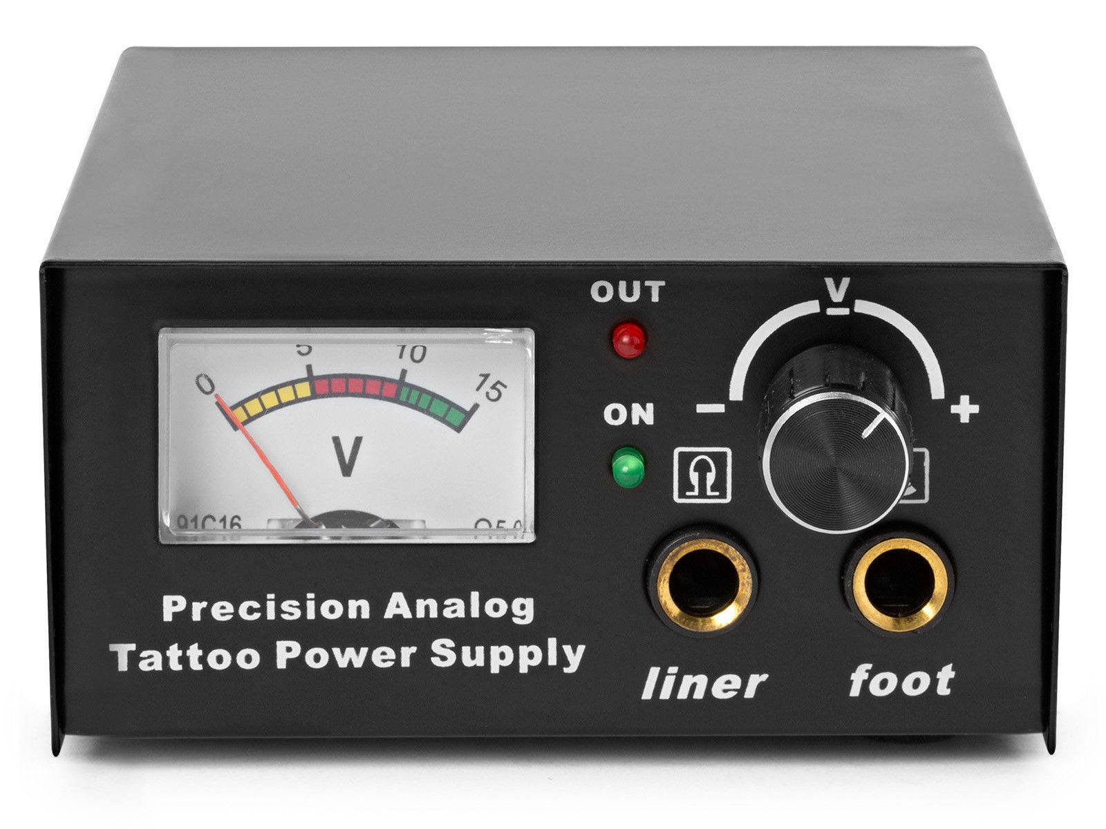
The idea behind this gadget surfaced while I was looking for something else and, although the front panel makes my skin crawl, it’s just an adjustable DC power supply:
Let’s say it has the potential to be a DC power supply, although we might quibble about the “Precision” part.
As delivered, it’s a deathtrap. Of course, it’s not UL listed and I didn’t expect it to be.
How many lethal problems do you see?
Tattoo power supply – original AC wiring
For starters, it has a three-wire AC line cord with the green-and-yellow conductor chopped off flush with the outer insulation inside the heatshrink tubing just behind the transformer:
Tattoo power supply – ungrounded AC line
The blue wire is AC neutral, but it really shouldn’t be connected to the finger-reachable outer fuse terminal.
The brown wire is AC line, which goes directly to one power switch terminal. In the event of a hot wiring fault, an unfused conductor touching the case will test the GFI you should have on your bench wiring.
The AC line cord uses some mysterious copper-colored metallic substance that’s about as stiff as music wire:
Tattoo power supply – stiff AC wire
The strands cannot be twisted together like ordinary copper wire, although they can be soldered. They may be copper-plated aluminum, because a magnet ignores them.
After soldering the strands together, they snap when bent:
Tattoo power supply – soldered broken AC wire
Generous strain relief is not just a good idea, it’s mandatory.
After some Quality Shop Time, the ground wire now connects to the case through the transformer’s rear mounting screw, the neutral AC wire connects to the transformer, the hot AC wire goes to the tip of the line fuse, and the fuse cap terminal goes to the switch:
Tattoo power supply – AC line rewiring
I relocated the white LED to the middle of the meter, where it looks a bit less weird:
Tattoo power supply – revised front panel
I have no idea what “Porket indicate” might mean. Perhaps “Precision indicator”?
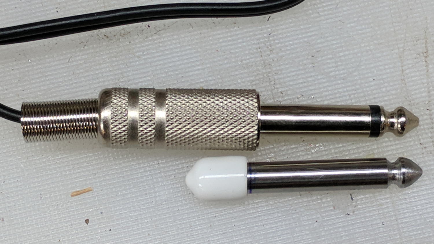
The right 1/4 inch jack, labeled “Foot”, normally goes to a foot switch you don’t need for a bench power supply, so I converted a length of drill rod into a dummy plug to short the jack contacts:
Tattoo power supply – dummy switch plug
The tip comes from a bit of lathe and file work and the white cap comes from a bag of wire shelf hardware.
A genuine hologram sticker (!) on the back panel proclaims “1.5 – 15 VDC 2 A”, which seemed optimistic. Some fiddling with power resistors suggests tattoo liners (I learned a new word!) don’t draw much current:
4 V @ 1 A
8 V @ 800 mA
10 V @ 600 mA
It can reach a bit over 18 V (pegging the meter) at lower current, so it’s Good Enough for small projects with un-fussy power requirements.