The Smell of Molten Projects in the Morning

Ed Nisley's Blog: Shop notes, electronics, firmware, machinery, 3D printing, laser cuttery, and curiosities. Contents: 100% human thinking, 0% AI slop.

Tag: Repairs

If it used to work, it can work again

  • Wyze V2 Camera: Tear-In

    One of my Wyze V2 cameras either arrived with dead IR hardware or failed early on in its tenure here, but it simply didn’t work in night-vision mode: the IR LEDs didn’t turn on and the IR-cut filter didn’t move. Neither the Official Wyze App nor the Xiaomi-Dafang Hacks firmware had any effect, so I expected a (possibly simple) hardware problem.

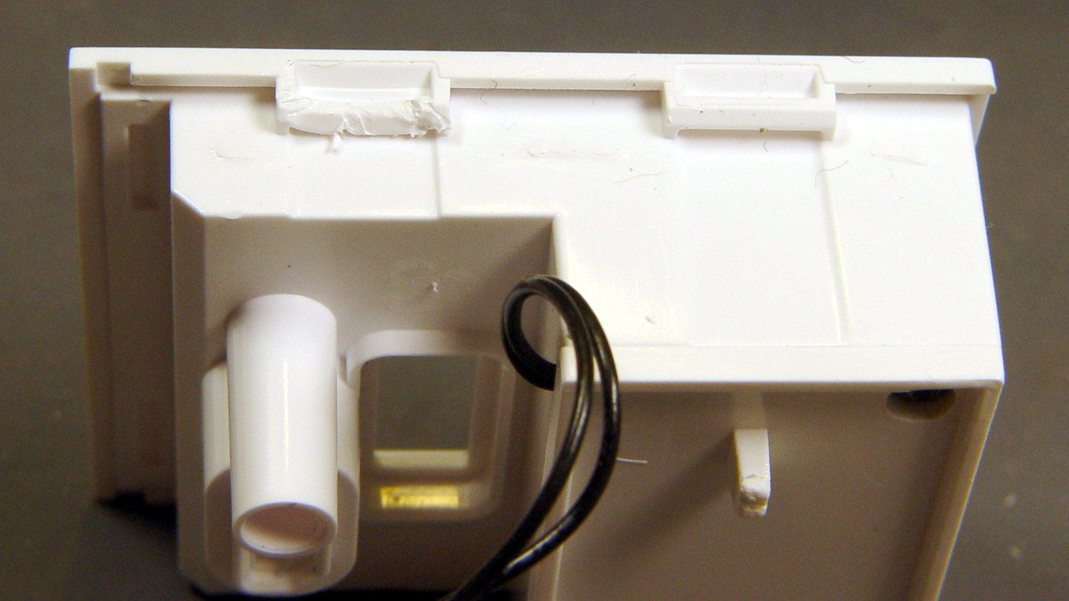
    The first hint of trouble was finding the case had only one of the two screws securing its bottom lid, with the missing screw having never been installed. Removing the single screw and prying a bit popped the lid, revealing the innards:

    Wyze V2 - interior bottom view
    Wyze V2 – interior bottom view

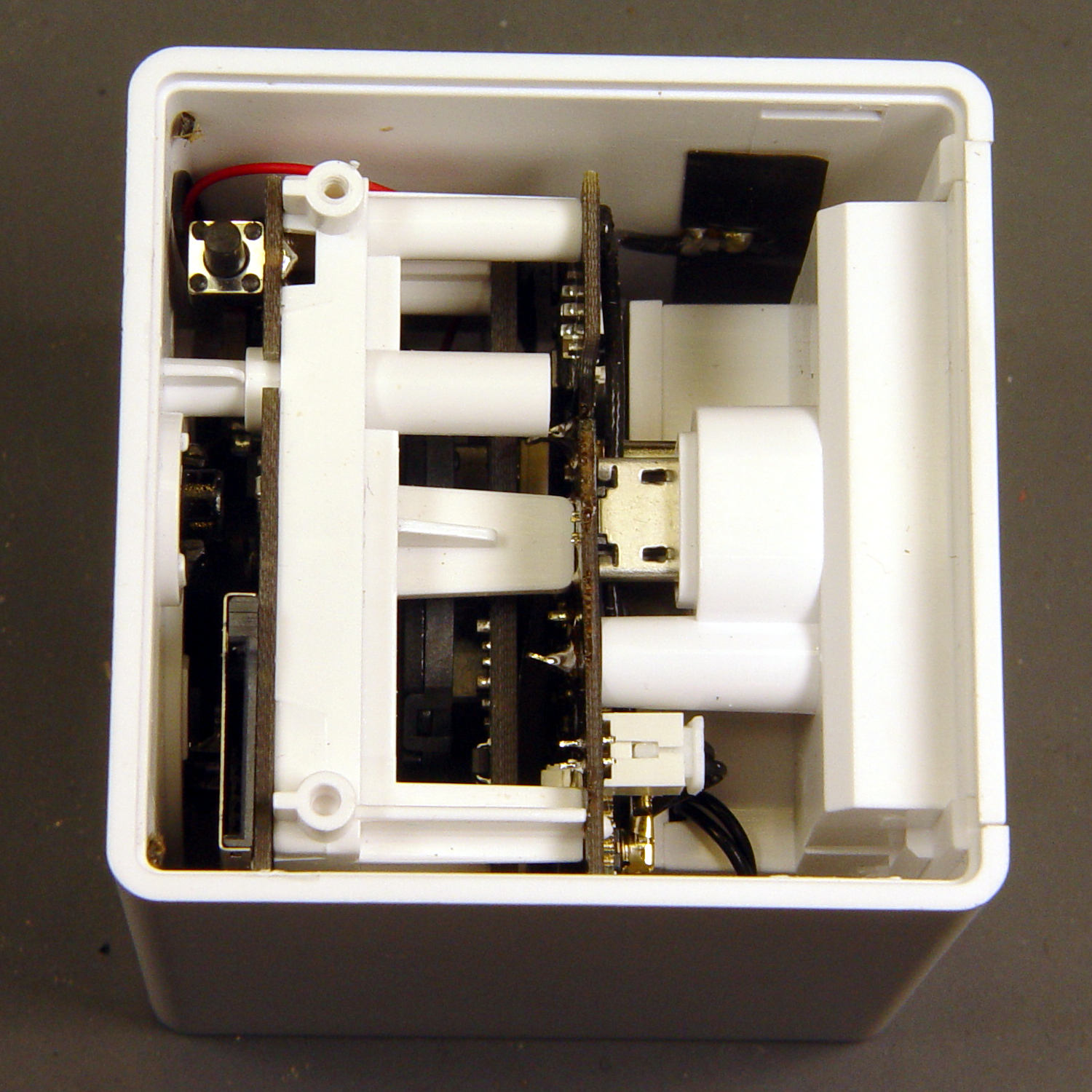
    The rear panel (on the right) comes off after abusing the snaps holding it to the main case:

    Wyze V2 - rear panel snaps
    Wyze V2 – rear panel snaps

    That’s best done with a small, designated Prydriver, rather than a screwdriver to which you have a deep emotional attachment.

    The corresponding part of the main body shows less abuse:

    Wyze V2 - case snaps - WiFi antenna
    Wyze V2 – case snaps – WiFi antenna

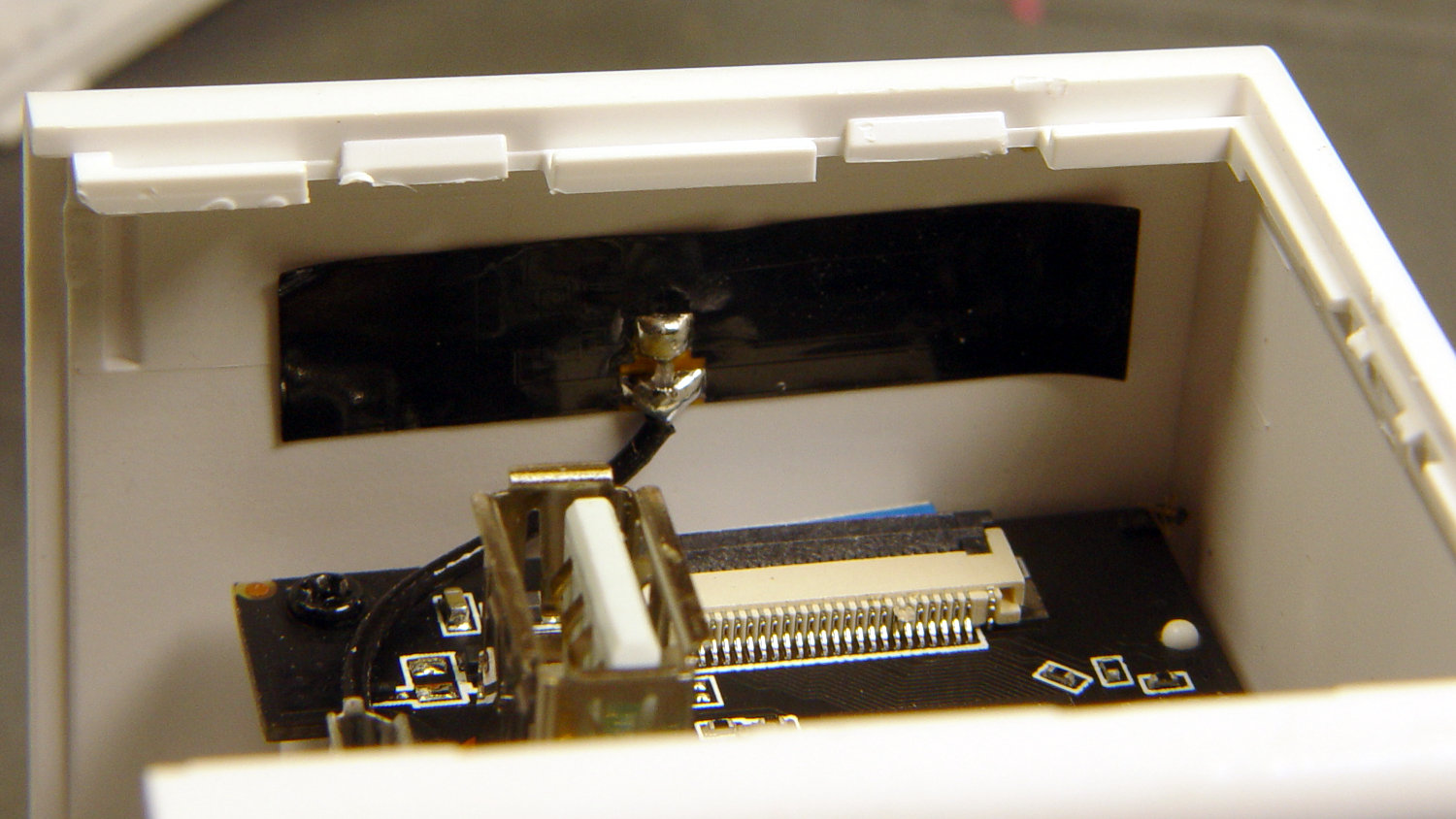
    The black patch is the WiFi antenna, which you must unplug from the top board before going much further.

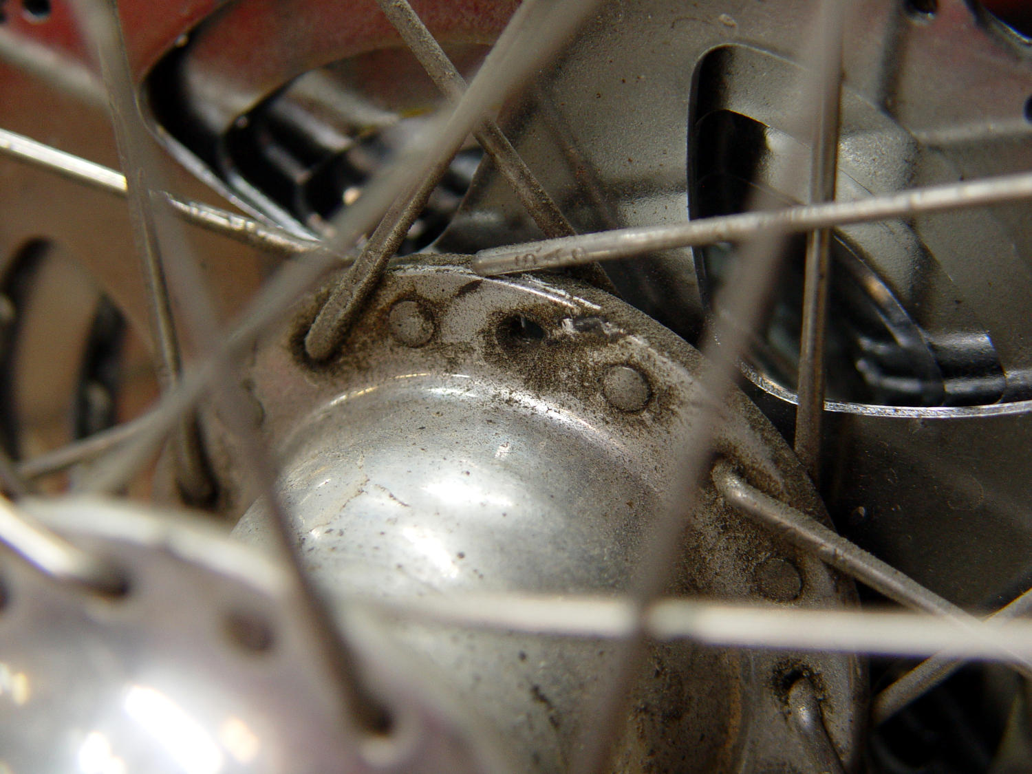
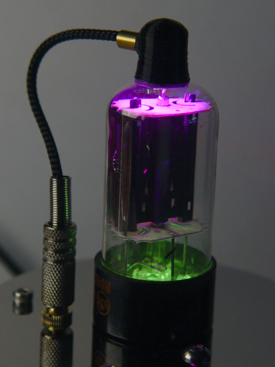
    The small blue wedge below the antenna gave me hope I’d found the root of the IR problem:

    Wyze V2 - mis-closed ribbon cable
    Wyze V2 – mis-closed ribbon cable

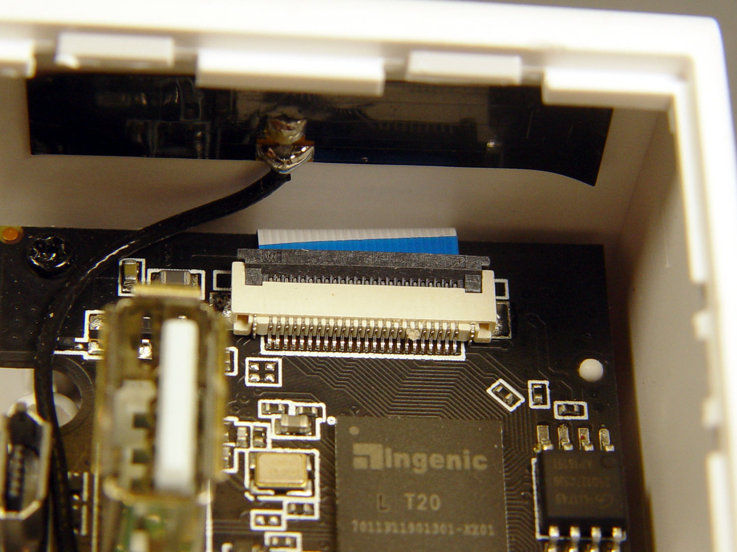
    Everybody has trouble with those delicate ribbon cable socket clamps!

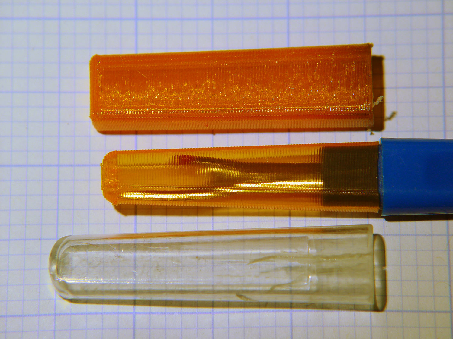
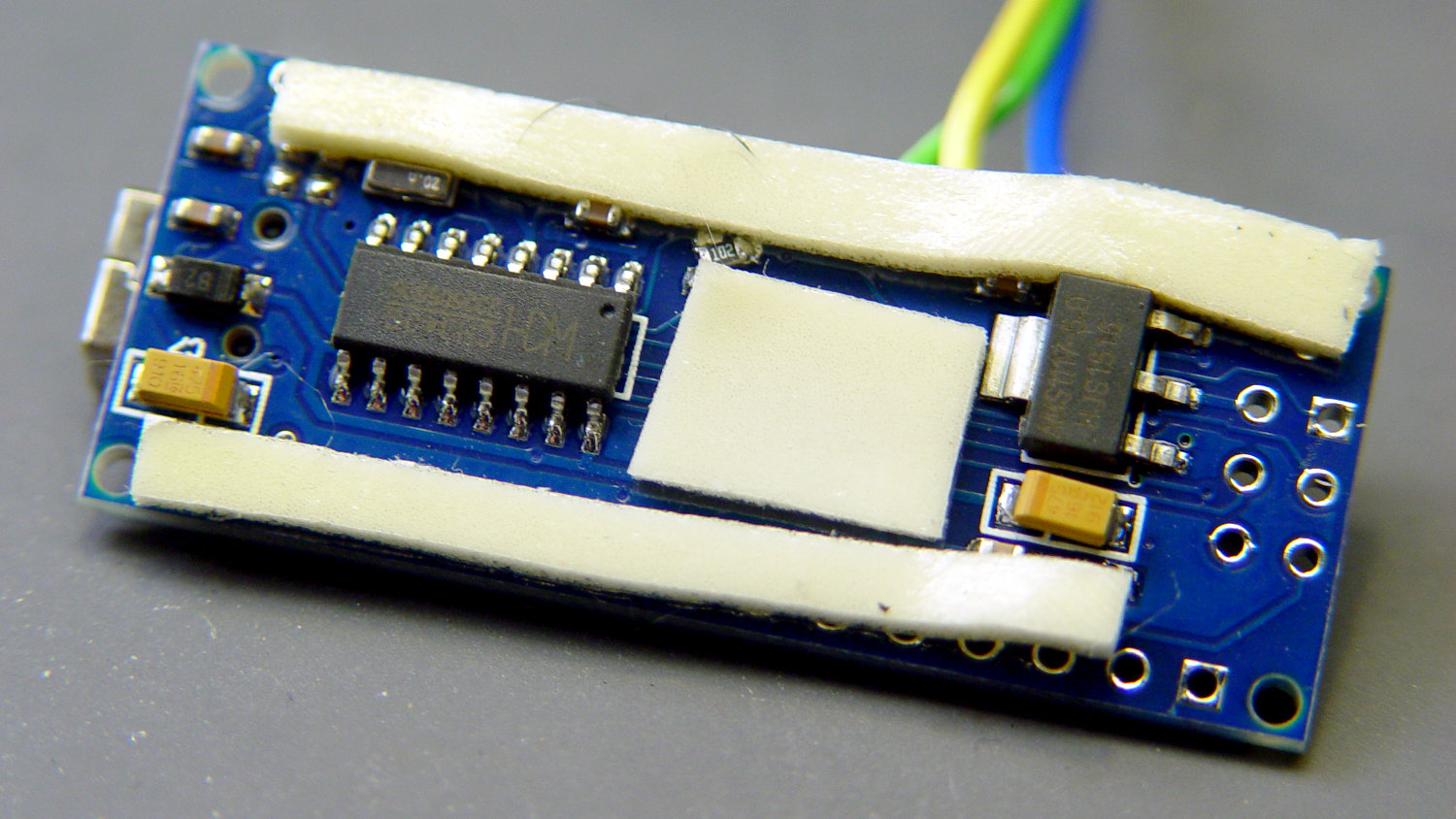
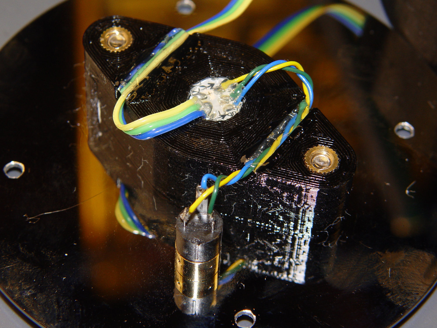
    While I had the case open, I extracted everything and looked it over:

    Wyze V2 - front PCB - LED pin soldering
    Wyze V2 – front PCB – LED pin soldering

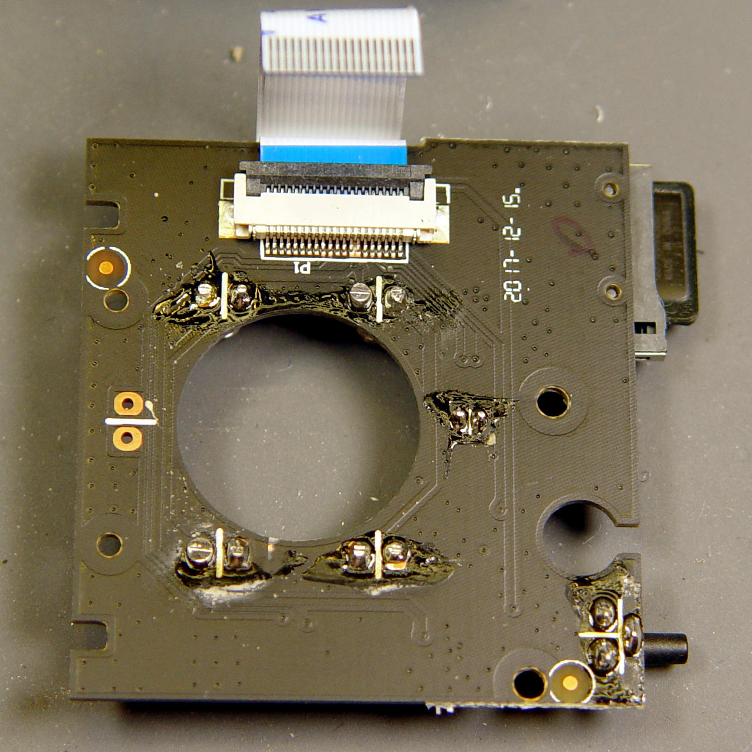
    The IR LED soldering left a bit to be desired, so I touched up those joints and washed off most of the flux.

    Alas, the IR hardware still didn’t work with everything stuffed back in the case. There are worse things than having a small daylight-only IP camera, though.

    So it goes …

  • Sony NP-FM50 Battery Disassembly

    Having won an eBay action for a known-dead Sony DSC-F717 at $0.99 (plus $15 shipping, the seller being no fool), I now have a possibly salvageable camera, a Genuine Sony AC supply, and two more NP-FM50 batteries for about the price of any one of the components.

    One battery arrived stone-cold dead, suggesting the camera had been put away with the battery installed for a very long time and they died companionably. The camera still charges a (good) battery, even though it doesn’t turn on, and perusing the schematics suggests checking the power switch, because it’s always the switch contacts. That’s for another day, though.

    For the record, the battery status:

    NP-FM50 - 2019-03-30
    NP-FM50 – 2019-03-30

    The red and green traces come from the two batteries I’ve been cycling through the camera since, um, 2003, so they’re getting on in years and correspondingly low in capacity.

    The fourth battery (2019 D, the date showing when it arrived, not its manufacturing date) went from “fully charged” to “dead” in about three seconds with a 500 mA load, producing the nearly invisible purple trace dropping straight down along the Y axis.

    Sawing the dead battery case around its welded joint at a depth of 0.75 mm, then prying with a small chisel, exposed the contents without histrionics:

    Sony NP-FM50 battery - cell label
    Sony NP-FM50 battery – cell label

    Now, there’s a name to conjure with. Turns out Sony sold off its Fukushima battery business a while back, so these must be collectibles. Who knew?

    The lower cell is lifeless, the upper cell may still have some capacity. Three pairs of 18500 lithium cells are on their way, in the expectation of rebuilding the weakest packs.

    After desoldering the battery tab on the right from the PCB, it occurred to me I needed pictures:

    Sony NP-FM50 battery - PCB exposed
    Sony NP-FM50 battery – PCB exposed

    Yeah, that’s a nasty melted spot on the case, due to inept solder-wickage.

    Unsoldering the three tabs closest to the case releases the cells + PCB from confinement:

    Sony NP-FM50 battery - PCB overview
    Sony NP-FM50 battery – PCB overview

    I’m still bemused by battery packs with a microcontroller, even though all lithium packs require serious charge controllers. At least this is an Atmel 8-bitter, rather than 32-bit ARM hotness with, yo, WiFi.

    The cells have shaped tabs which will require some gimmicking to reproduce:

    Sony NP-FM50 battery - cell tabs
    Sony NP-FM50 battery – cell tabs

    Now, if only I could reboot the camera …

  • Broken Spoke

    On the drive side, of course:

    Tour Easy - broken rear spoke
    Tour Easy – broken rear spoke

    I’d noticed some brake drag on our last few rides, but forgot to check until I saw the rim wobble while extracting images from the rear camera.

    It’s a lot easier to fix in the Basement Shop than on the road. After nigh onto a decade since replacing the last broken spoke, perhaps this is a harbinger of doom to come.

    Memo to Self: spoke tension is now 20-ish on the drive side, 15-ish on the left.

  • Seam Ripper Cover

    The cover for Mary’s favorite seam ripper cracked long ago, has been repaired several times, and now needs a replacement:

    Seam Ripper cover - overview
    Seam Ripper cover – overview

    The first pass (at the top) matched the interior and exterior shapes, but was entirely too rigid. Unlike the Clover seam ripper, the handle has too much taper for a thick-walled piece of plastic.

    The flexy thinwall cover on the ripper comes from a model of the interior shape:

    Seam Ripper Cover - handle model
    Seam Ripper Cover – handle model

    It’s not conspicuously tapered, but OpenSCAD’s perspective view makes the taper hard to see. The wedge on top helps the slicer bridge the opening; it’s not perfect, just close enough to work.

    A similar model of the outer surface is one thread width wider on all sides, so subtracting the handle model from the interior produces a single-thread shell with a wedge-shaped interior invisible in this Slic3r preview:

    Seam Ripper Cover - exterior - Slic3r preview
    Seam Ripper Cover – exterior – Slic3r preview

    The brim around the bottom improves platform griptivity. The rounded top (because pretty) precludes building it upside-down, but if you could tolerate a square-ish top, that’s the way to go.

    Both models consist of hulls around eight strategically placed spheres, with the wedge on the top of the handle due to the intersection of the hull and a suitable cube. This view shows the situation without the hull:

    Seam Ripper Cover - handle model - cube intersection
    Seam Ripper Cover – handle model – cube intersection

    The spheres overlap, with the top set barely distinguishable, to produce the proper taper. I measured the handle and cover’s wall thicknesses, then guesstimated the cover’s interior dimensions from its outer size.

    The handle’s spheres have a radius matching its curvature. The cover’s spheres have a radius exactly one thread width larger, so the difference produces the one-thread-wide shell.

    Came out pretty nicely, if I do say so myself: the cover seats fully with an easy push-on fit and stays firmly in place. Best of all, should it get lost (despite the retina-burn orange PETG plastic), I can make another with nearly zero effort.

    The Basement Laboratory remains winter-cool, so I taped a paper shield over the platform as insulation from the fan cooling the PETG:

    Seam Ripper Cover - platform insulation
    Seam Ripper Cover – platform insulation

    The shield goes on after the nozzle finishes the first layer. The masking tape adhesive turned into loathesome goo and required acetone to get it off the platform; fortunately, the borosilicate glass didn’t mind.

    The OpenSCAD source code as a GitHub Gist:

    // Cover for old seam ripper
    // Ed Nisley – KE4ZNU
    // 2019-03
    /* [Layout Options] */
    Layout = "Build"; // [Show,Build]
    Part = "Handle"; // [Handle,CoverSolid,Cover]
    /* [Extrusion Parameters] */
    ThreadWidth = 0.40;
    ThreadThick = 0.25;
    HoleWindage = 0.2;
    Protrusion = 0.1;
    //—–
    // Dimensions
    /* [Dimensions] */
    WallThick = 1*ThreadWidth;
    CapInsideLength = 48.0;
    CornerRadius = 2.0; // handle at base
    Base = [11.0,5.5,0.0]; // handle at base
    Tip = [8.2,3.7,CapInsideLength]; // inferred at tip
    HandleOC = [Base – 2*[CornerRadius,CornerRadius,0.0],
    Tip – 2*[CornerRadius,CornerRadius,CornerRadius/2]
    ];
    NumSides = 2*3*4;
    //—–
    // Useful pieces
    // Handle is basically the interior of the cover
    module Handle() {
    intersection() {
    hull()
    for (i=[-1,1], j=[-1,1], k=[0,1])
    translate([i*HandleOC[k].x/2,j*HandleOC[k].y/2,k*HandleOC[k].z])
    sphere(r=CornerRadius,$fn=NumSides);
    translate([0,0,-CornerRadius/2]) // chop tip for better bridging
    rotate([45,0,0])
    cube([2*Base.x,CapInsideLength*sqrt(2),CapInsideLength*sqrt(2)],center=true);
    }
    }
    module CoverSolid() {
    hull()
    for (i=[-1,1], j=[-1,1], k=[0,1])
    translate([i*HandleOC[k].x/2,j*HandleOC[k].y/2,k*HandleOC[k].z])
    sphere(r=CornerRadius + WallThick,$fn=NumSides);
    }
    module Cover() {
    difference() {
    CoverSolid();
    Handle();
    translate([0,0,-CornerRadius])
    cube(2*Base + [0,0,2*CornerRadius],center=true);
    }
    }
    //—–
    // Build things
    if (Layout == "Build") {
    Cover();
    }
    if (Layout == "Show")
    if (Part == "Handle")
    Handle();
    else if (Part == "CoverSolid")
    CoverSolid();
    else if (Part == "Cover")
    Cover();

  • “New” Phone Battery

    Having an ancient flip phone in need of a battery, I ordered a Kyocera TXBAT10133 battery from eBay. Described as “new” (which, according to the Ebay listing, means “New: A brand-new, unused, unopened, undamaged item in its original packaging”), I was somewhat surprised to see this emerging from the box:

    Kyocera TXBAT10133 - not really new
    Kyocera TXBAT10133 – not really new

    It obviously led a rather hard life before being harvested from somebody else’s obsolete flip phone and is definitely not “new”.

    Not yet having a deep emotional attachment to the thing, I set it up for a capacity test:

    Kyocera TXBAT10133 - contact clamp
    Kyocera TXBAT10133 – contact clamp

    Given a very light 100 mA load, it shows about the same capacity as the original battery in our phone:

    Kyocera TXBAT10133 - 2019-03-29
    Kyocera TXBAT10133 – 2019-03-29

    Given the precarious contact arrangement, the glitches near the right end aren’t surprising.

    The battery label claims a 900 mA·h rating, so both have nearly their nominal capacity at such a reduced load. In actual use, the phone has a low battery after a few hours of power-on time, far less than when it was new.

    The seller promises a replacement. For all I know, there are no genuinely “new” batteries available for these phones.

  • Monthly Science: Weight

    We’d been eating a “healthy” high-carb / low-fat diet, which produced the more-or-less expected 1 lb/yr weight gain over the course of three decades. Given that we eat about 106 Cal/yr, being off by a mere 0.3% seemed fixable, but we were always hungry while trying to cut out calories.

    In April 2016, we decided our tummies had come between us, so we switched to a mostly ketogenic diet (clicky for more dots):

    Weight Chart 2016 - Ed
    Weight Chart 2016 – Ed

    Having a Master Gardener in the family complicates dietary choices along the ketogenic axis, but Mary raised more green-and-leafy veggies, less squash-and-corn, and we keto-ized our meals reasonably well. Moderation in all things works fine for us, so losing 25 pounds at about 1 lb/week wasn’t particularly stressful.

    Continuing through 2017, you can see how regular bike riding season affects winter bloat:

    Weight Chart 2017 - Ed
    Weight Chart 2017 – Ed

    Our cycling vacation in July 2018 produced a blip, but the rest of the riding season worked as expected:

    Weight Chart 2018 - Ed
    Weight Chart 2018 – Ed

    It’s straightforward to crash-diet two dozen pounds, but maintaining a more-or-less stable weight for the next two years suggests we’ve gotten the annual calorie count about right. FWIW, my bloodwork numbers sit in the Just Fine range, apart from the somewhat elevated cholesterol level typical of a keto-ized diet.

    Starting in late 2018, however, a stressful situation of a non-bloggable nature (at least for a blog such as this) produced an unusually high number of road trips, motel stays, and generally poor dietary choices:

    Weight Chart 2019-03 - Ed
    Weight Chart 2019-03 – Ed

    The situation now being over, our lives / exercise / diet will return to what passes for normal around here and my goal is to lose another 10% of my current body weight, ending at 150 pounds, by the end of the year. In round numbers, that requires losing half a pound = 1700 Cal/week, 250 Cal/day. Not power-noshing an ounce or two of nuts a day should do the trick.

    If it makes you feel more science-y, you can use the NIH Body Weight Planner, but it produces about the same answer: knock off 300 Cal to lose weight, 250 Cal to maintain it, at essentially the same exercise level as before.

    We’ve been recording our weights as dots on graph paper every Saturday evening for the last four decades, so I know for a fact I averaged 148 pounds when I wore a younger man’s clothes. I’ll re-post the 2019 chart, adding four dots every month, during the rest of the year.

    This way, you can help keep me on track … [grin]

  • Vacuum Tube Lights: Triode

    With the wrecked 5U4GB safely in the trash, I popped a smaller, somewhat less stately triode from the Big Box o’ Hollow-State Electronics and wired it up with a pair of SK6812 RGBW LEDs:

    Triode - Purple-green phase
    Triode – Purple-green phase

    The tube’s markings have long since vanished, but, at this late date, all that matters is an intact glass envelope!

    After two years, the ordinary white foam tape holding the knockoff Arduino Nano lost most of its sticktivity and easily popped off the 3D printed base:

    Triode - Nano PCB - white strips
    Triode – Nano PCB – white strips

    Two layers of 3M outdoor-rated foam tape clear the bottom-side components and, based on current evidence, its stickiness should stick forever more:

    Triode - Nano PCB - 3M strips
    Triode – Nano PCB – 3M strips

    The alert reader will notice the mis-soldered 1 kΩ SMT resistor above-and-right of the CH340 USB interface chip. I think those two resistors are the isolators between the 328P microcontroller and the CH340, letting you use the TX and RX lines as ordinary I/O without killing either chip.

    Despite the mis-soldering, it evidently passed their QC and works fine. Seeing as how I didn’t notice it until just now, it’ll remain in place until I must open the lamp base for some other reason, which may never happen.

    The data output is now on pin A5, to match the rest of the glowing widgetry:

    Triode - Nano installed
    Triode – Nano installed

    Blobs of hot melt glue affix the SK6812 and wiring to the socket:

    Triode - socket wiring
    Triode – socket wiring

    The original “plate cap” wiring ran directly through a hole in the hard drive platter, which I embiggened for a 3.5 mm panel-mount headphone jack. The knurled metal plug looms next to this smaller tube, but it looks better (in a techie sense) than the raw hole:

    Triode - plate cap plug
    Triode – plate cap plug

    Octal tubes have an opaque Bakelite base, so I devoted some Quality Shop Time™ to the post:

    Triode - base tip exposed
    Triode – base tip exposed

    Although I’d made a shell drill for 5U4’s base, this base was so crumbly I simply joysticked the spinning cutter around to knock off the rest of the post:

    Triode - finished base
    Triode – finished base

    The shell drill would open the bottom to admit a bit more light. I may do that to see if it makes any visible difference.

    I didn’t expect the serrations in the top mica plate to cast interesting patterns around the platter:

    Triode - cyan-purple phase
    Triode – cyan-purple phase

    Memo to Self: use the shell drill to avoid nicking the evacuation tip!