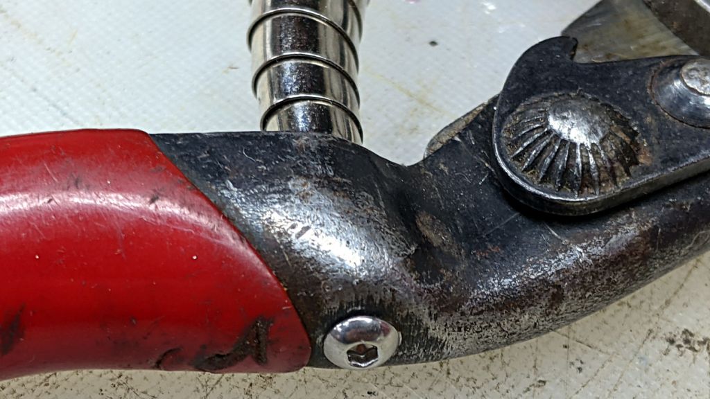
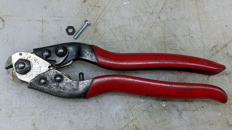
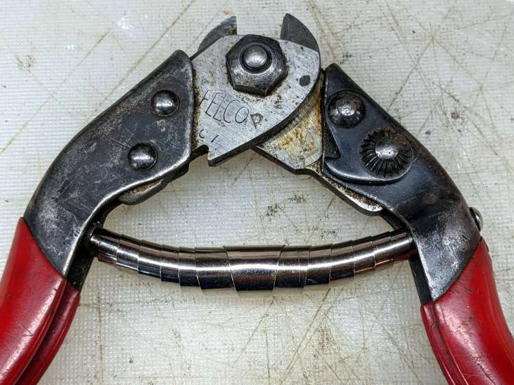
The back of the Pliers & Cutters drawer produced an ancient Felco C7 Cable Cutter minus its spring:
That’s an M4 screw serving as a size test for the hole where the other pin used to be.
Surprisingly, Felco still exists, still makes the C7 Cable Cutter, and actually sells a replacement spring as part number C7/10. Unfortunately, their online sales apparatus and cart seem broken: I put the spring in the cart, but found no way to pay for it. Worryingly, the usual Terms & Conditions link produced a modal dialog with one word: TEST.
So I got a spring (part number 5/11, available only as a pair in kit 5/91) for a Felco C3 cutter (no, the numbers do not match) from Amazon. Later I found a sketchy seller offering a sketchy C7/10 spring that might fit correctly or could be total trash.
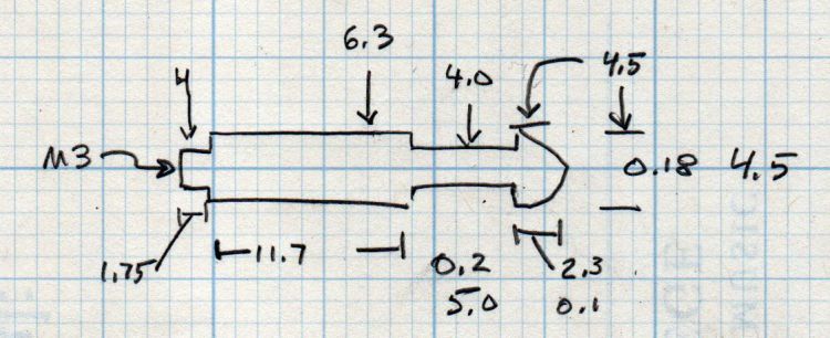
Felco swaged the original spring pins into the handle, a manufacturing technique I certainly cannot duplicate, but an M3 screw will just barely fit inside a 4 mm stud, so I made some measurements:
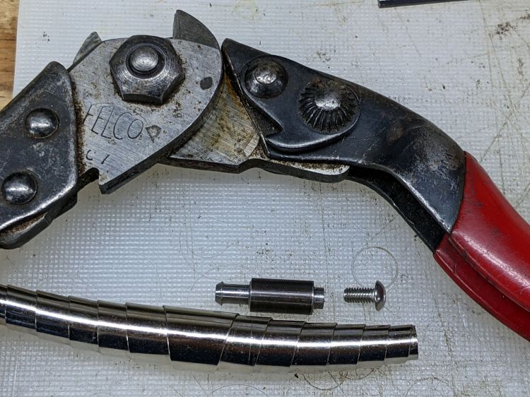
Fitting action to words:
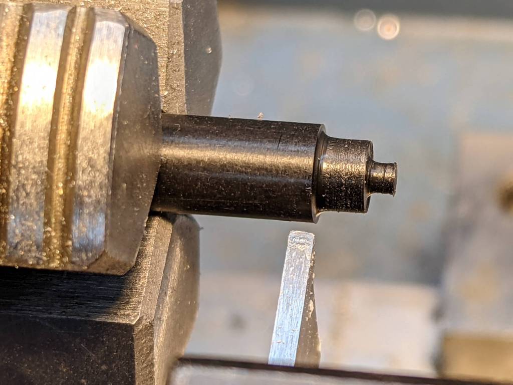
That started as a 1/4 inch rod of no particular provenance and is reasonably close to the actual dimensions.
The spigot on the screw end is threaded M3 and is just barely shorter than the thickness of the handle, so the button-head screw can pull it snug:

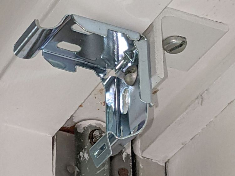
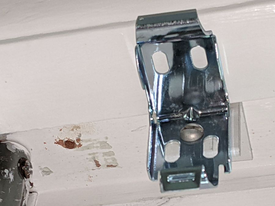
And then the spring just snapped into place:
It it obviously grossly excessively too long, but that really doesn’t matter for the number of power-on hours it’s likely to see during my administration. In truth, it feels pretty good in the hand after releasing the latch and having it expand smoothly.
If I ever run across a C7/10 spring, it’ll be an easy swap.