Ed Nisley's Blog: Shop notes, electronics, firmware, machinery, 3D printing, laser cuttery, and curiosities. Contents: 100% human thinking, 0% AI slop.
While replacing the well-worn sprocket / chain / chainrings on Mary’s bike, I finally got around to repairing some damaged paint tucked in an inconvenient spot…
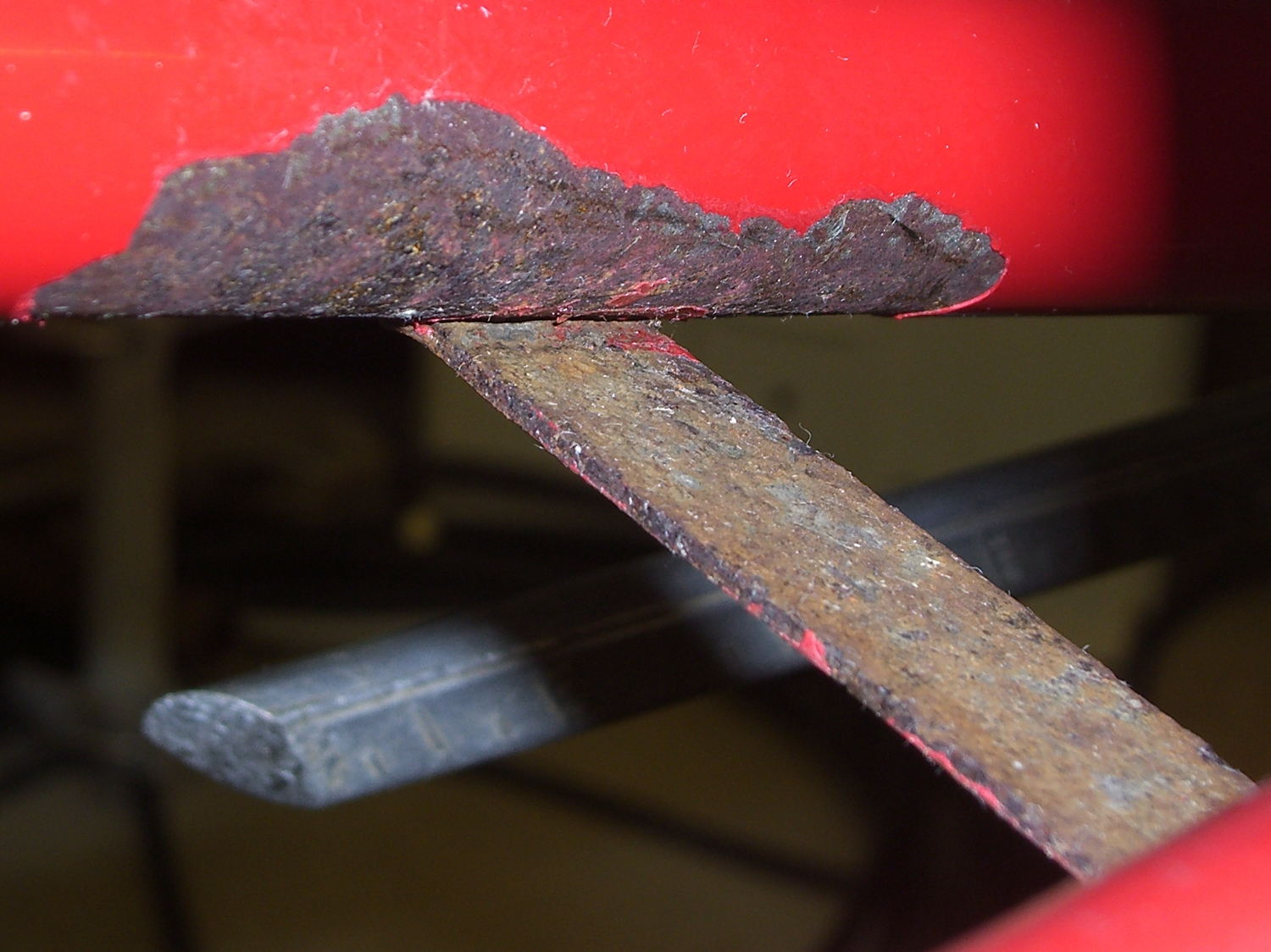
Over the years, a flaw in the paint underneath the strap connecting the chainstays on Mary’s Tour Easy let in enough moisture to dislodge the paint over a considerable area. I chipped off the loose paint and used Evapo-Rust to convert the oxide to phosphate; there’s not much damage to the steel parts, despite what it may look like in the pictures.
A top view from the right rear, minus the wheel & fender, looking toward the left chainstay:
Tour Easy – rusted chainstay strap
Two epoxy fillets in the concave sections where the strap meets the chainstays should eliminate problems in those sections forever more:
Tour Easy – chainstay strap – epoxy fillet
Some rusty-metal primer and a few coats of red paint conceal most of the ugliness:
Tour Easy – rear fender bracket – installed – top
It’ll never be mistaken for showroom quality, but our bikes are tools, not art objects.
The obviously 3D printed red block in the middle of the strap holds the fender in place, about which more tomorrow…
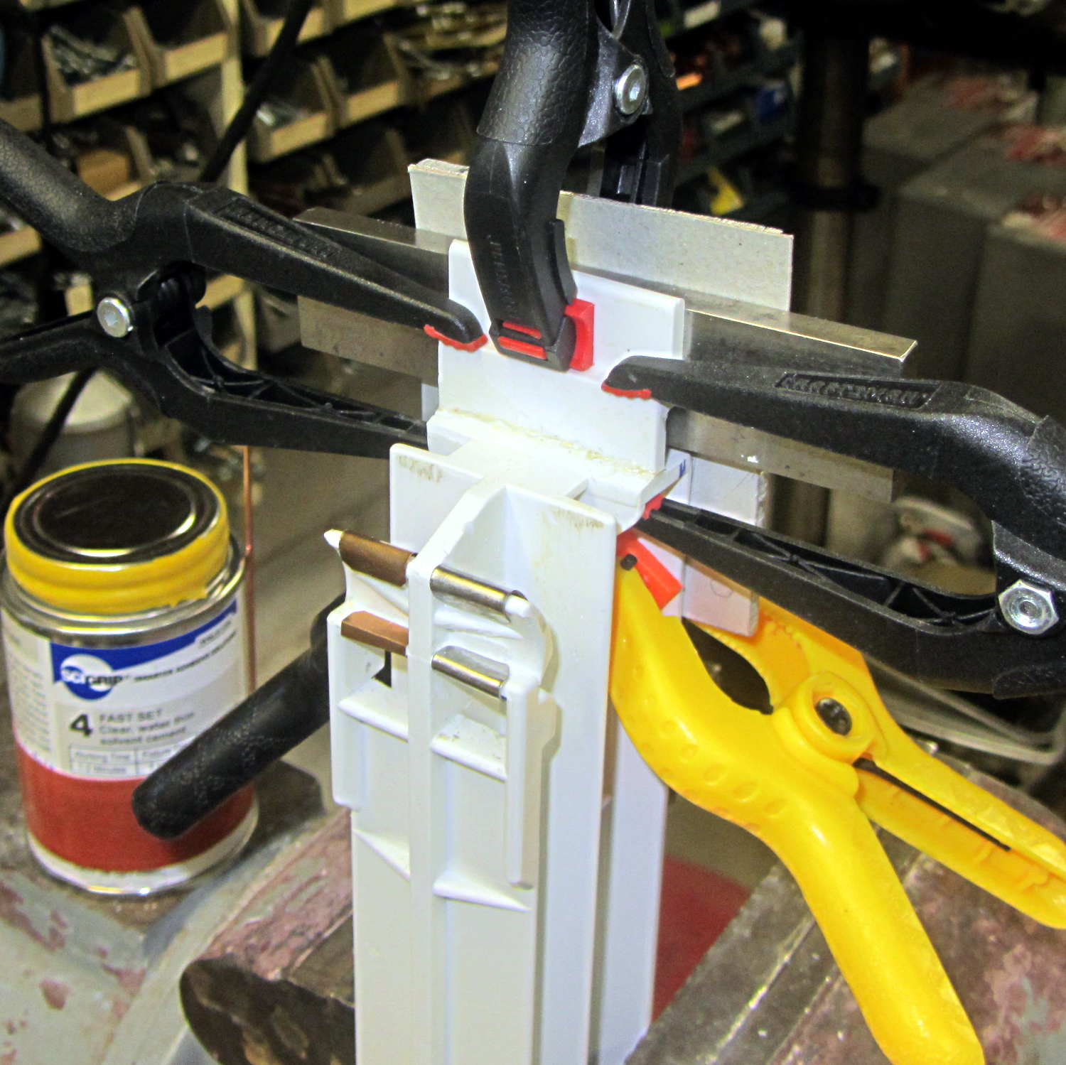
Well, another year, another deep-cleaning session, another break in the strut holding up the drawers in the Whirlpool refrigerator:
Whirlpool refrigerator drawer strut – clamped
This time, there’s a fixture positioning the tab in the proper orientation while the solvent evaporates. The two bottom clamps hold an aluminum plate against the top (far side) of the strut, with the top-center clamp holding the tab against a steel block shimmed with cardboard to get the correct angle. The other two clamps squash the tab against the joint, which is well-soaked with IPS 4 adhesive.
I replaced the right-side guide plate, originally made from phosphor bronze strip, with some thicker steel strip. The bronze strip collapsed into the worn section of the plastic bump that appeared in the previous post:
Refrigerator strut – worn retainers
I’ve written bigger caution messages on the top of the strut in red letters, but we think it’s getting on time for a whole new refrigerator…
First up: it’s not our projector, which means the usual Rules of Engagement do not apply.
A few small black plastic fragments fell out of the Epson S5 projector’s carry bag, the front foot wouldn’t remain extended, and, as one might expect, the two incidents were related. Mary needed it for the gardening class she was teaching the next evening, sooooo…
A pair of plastic snaps release the entire foot assembly from the front of the projector:
Epson S5 Projector Foot – assembled
It became obvious that we didn’t have all the fragments, but it was also obvious that, even if we had the pieces, a glued assembly wouldn’t last very long.
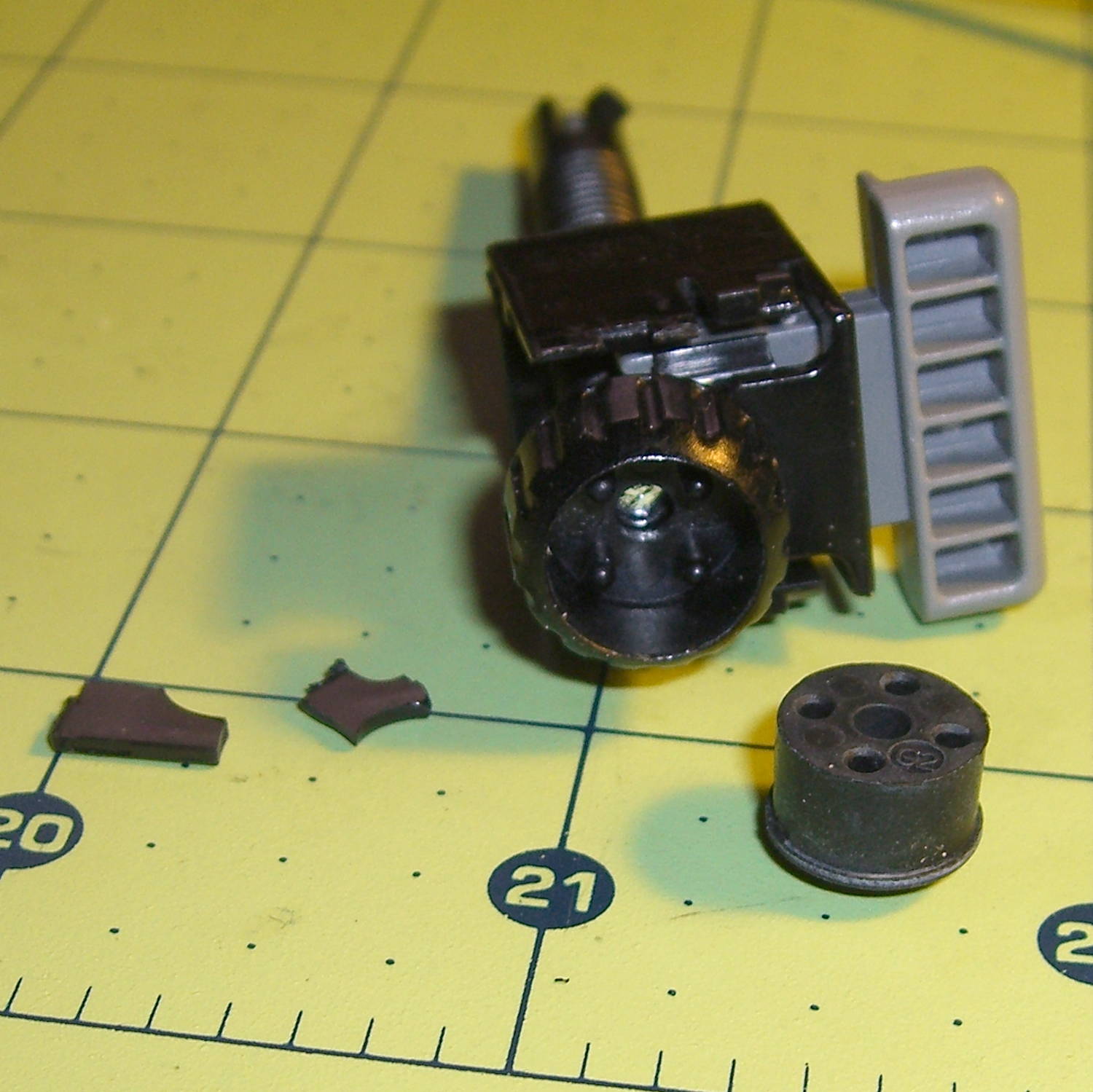
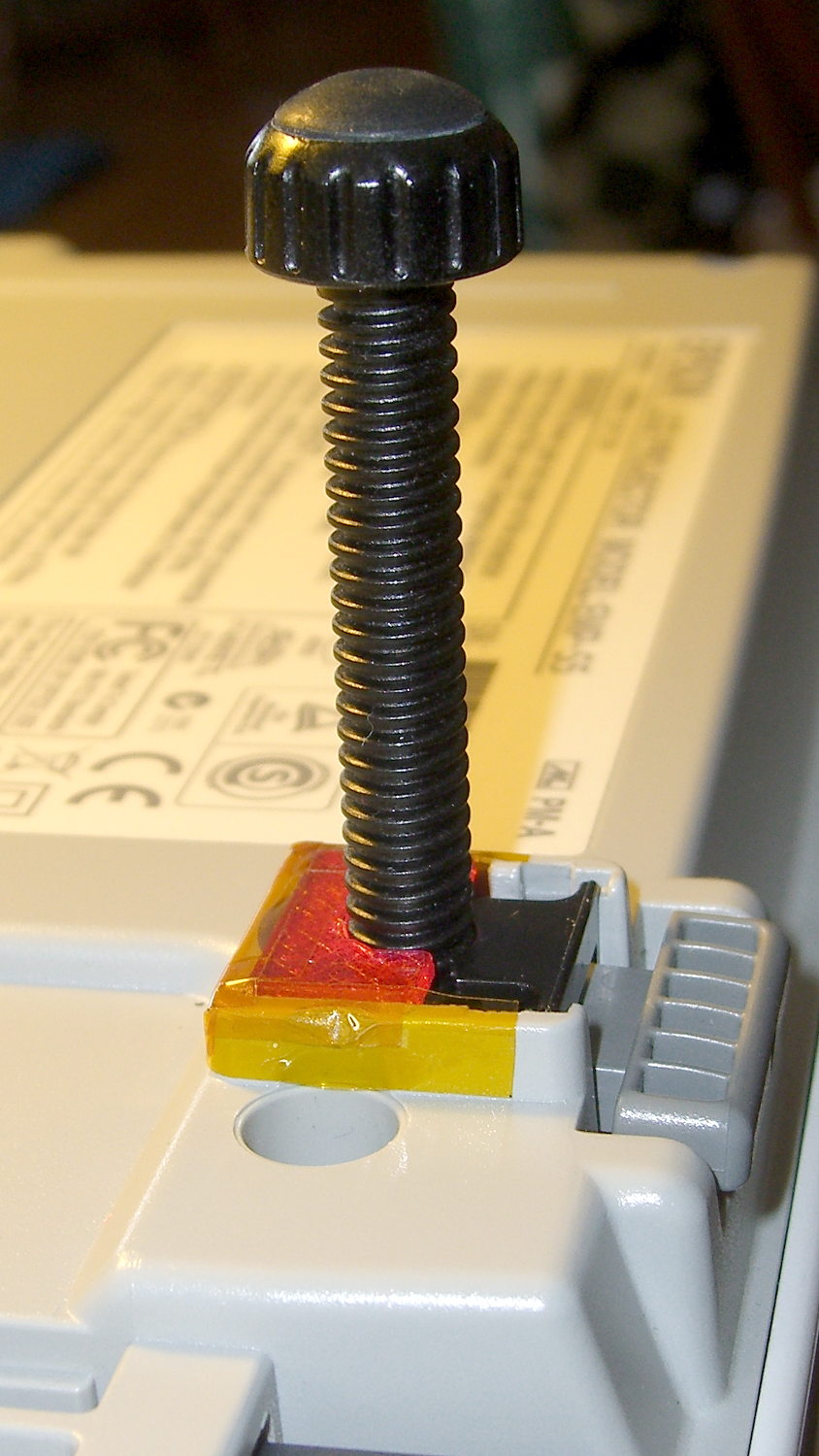
The threaded plastic stem surrounds a steel pin that’s visible when you remove the rubber foot pad. That pin holds the latch on the end of the stem outward, so that the stem can’t fall out. Drive out the pin with a (wait for it) pin punch inserted from the foot pad end, which reveals the broken plastic doodad:
Epson S5 Projector Foot – stem removed
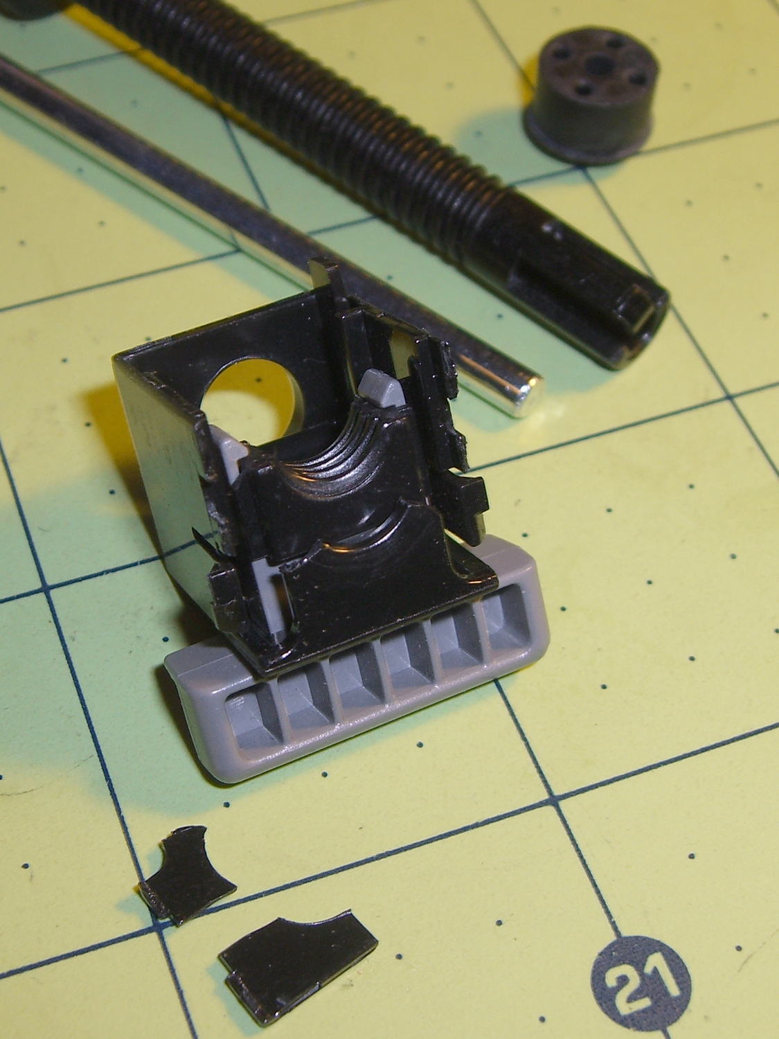
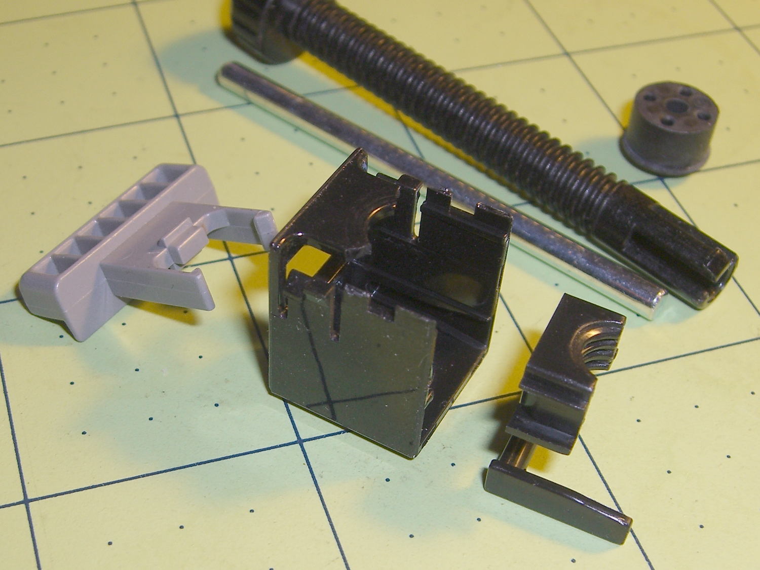
Release the latches on the gray handle and the intricate half-nut that engages the threaded stem slides out:
Epson S5 Projector Foot – disassembled
A plastic spring in the boxy shell pushes the gray handle and half-nut against the stem, holding the stem in place. Pushing the gray handle upward (on the projector, downward in the picture, yes, your fingertip can feel those ribs just fine) pulls the half-nut away from the stem and lets the stem slide freely. With the stem extended, the projector leans on the stem, pushes it against the half-nut, and you can fine-tune the angle by turning the stem; the splines around the rubber foot encourage that. You can pull the stem outward without activating the latch, which probably broke the fragile plastic plate.
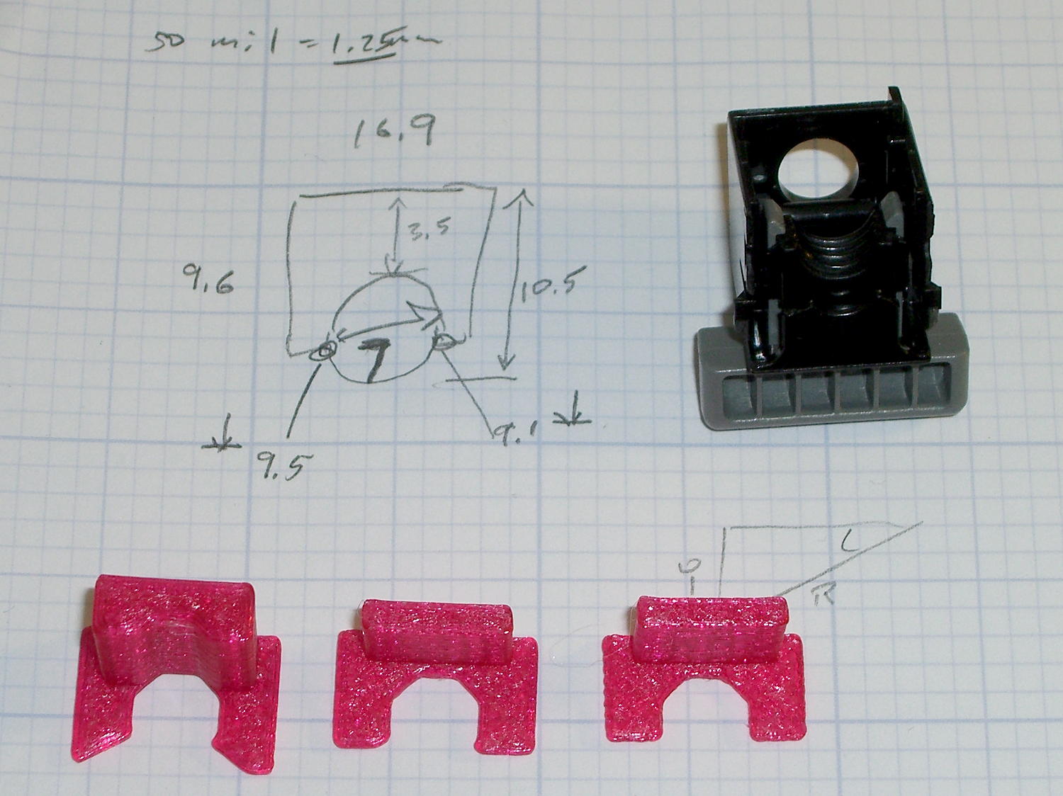
A doodle showing the estimated measurements, plus three 3D printed prototypes required to get a good fit:
Epson S5 Projector Foot – measurements and versions
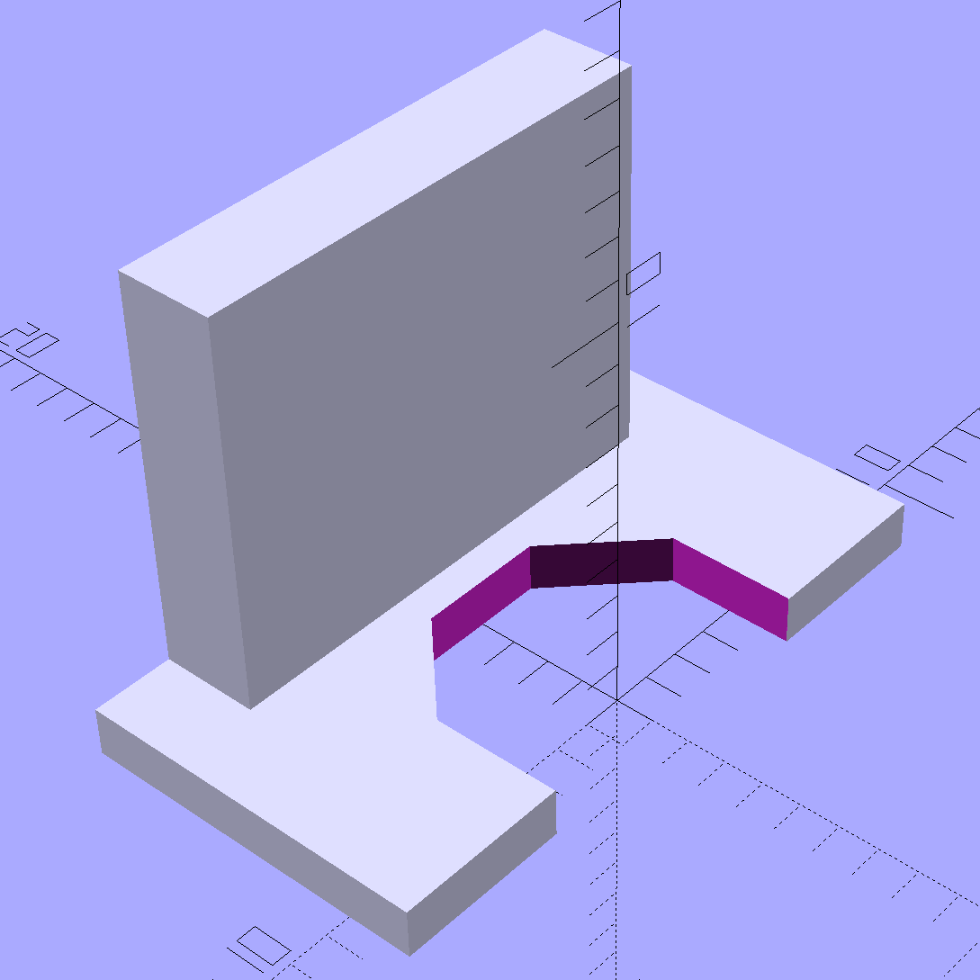
The solid model looks about like you’d expect:
Epson S5 Projector foot latch – solid model
The first version (leftmost of the three sitting on the doodle, above) had angled ends on the tabs that I intended to match up with the stubs remaining on the OEM latch. The part fit better with shorter tabs and the angles vanished on third version; the statements remain in the OpenSCAD source, but the short tabs render them moot.
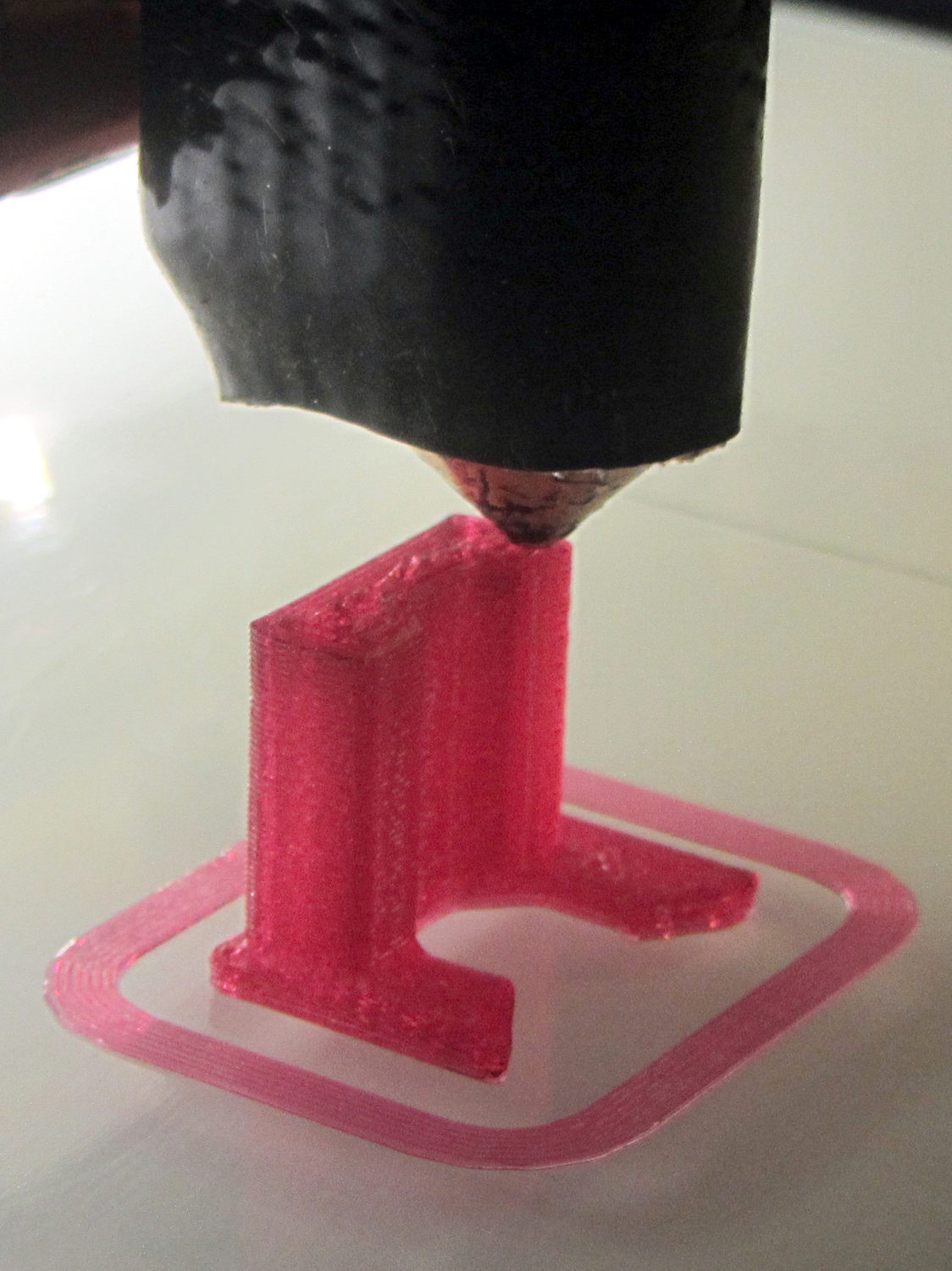
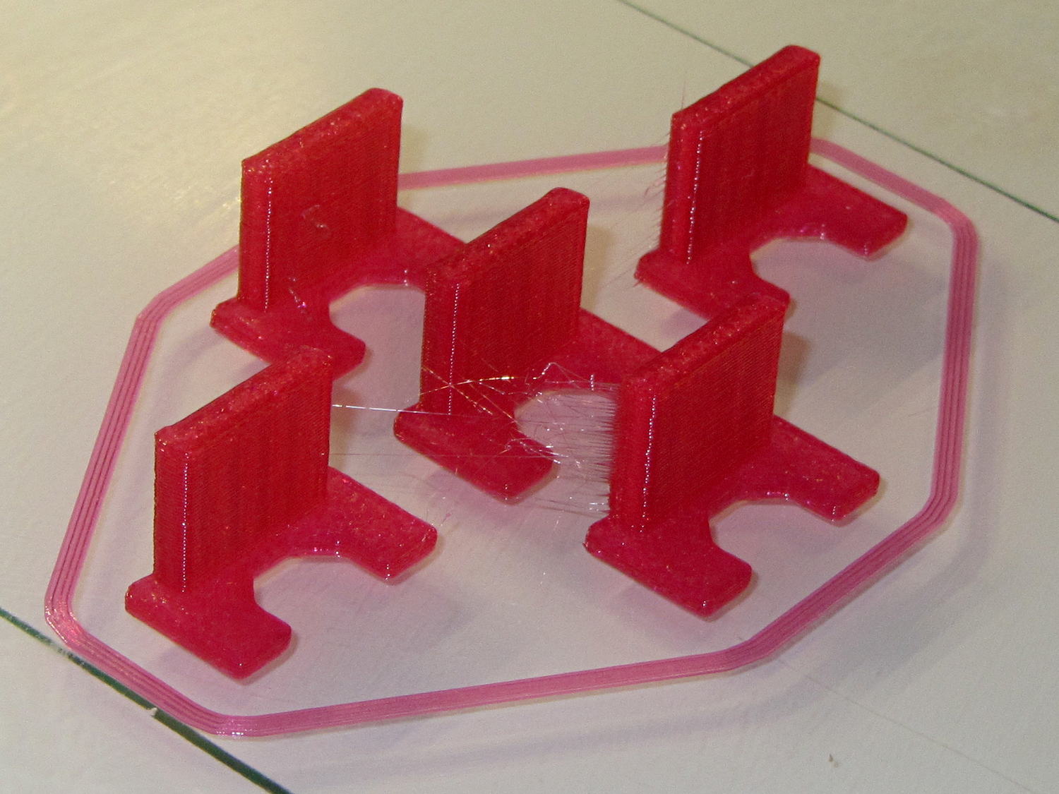
Apparently I got the cooling & fan & minimum layer time pretty close to right for PETG, as each of those three towers printed singly with no slumping:
Epson S5 Projector Foot – V1 on platform
The third version snapped into place, with a square of tapeless sticky on the back to help keep it there. The obligatory Kapton tape helps retain it, but I have no illusions about the permanence of this repair:
Epson S5 Projector Foot – repair installed
Because I know the problem will happen again, I called for backup:
Epson S5 Projector Foot – 5 copies
That’s with Hilbert Curve top / bottom fill, three top / bottom layers, 20% rectilinear infill, and two perimeters. Extruder at 250 °C, platform at 90 °C, hairspray for adhesion.
Note, however, the hair-fine strings connecting the towers. Retraction must be just about right, as shown by the overall quality of the objects, but PETG comes out really stringy. Choosing an infill pattern to minimize retraction seems like a big win; relatively sparse 3D Honeycomb works well on larger objects, but these were so small that straight line fill fit better. The flat plates on the bottom consist of five completely solid layers of PETG.
Reports from the field indicate complete success: whew!
One could, of course, just buy a replacement from the usual eBay supplier, if one were so inclined.
Our Larval Engineer reports that the PLA pivot for the Sienna’s hood rod didn’t survive contact with the van’s NYS Inspection. I’m not surprised, as PLA tends to be brittle and the inspection happened on a typical February day in upstate New York. Seeing as how PETG claims to be stronger and more durable than PLA, I ran off some replacements:
Toyota Sienna hood rod pivot – small – PETG
The square cap fit snugly over the bottom of the post; PETG tolerances seem pretty much the same as for PLA.
A slightly larger loop may be more durable, so I changed one parameter in the OpenSCAD code to get this:
Toyota Sienna Hood Rod Pivot – up-armored – solid model
Which printed just like you’d expect:
Toyota Sienna hood rod pivot – large – PETG hairs
Despite the hairs stretching between each part, the nozzle didn’t deposit any boogers during the print. The top and bottom use Hilbert Curve infill, which looks pretty and keeps the nozzle from zipping back and forth quite so much; perhaps that’s a step in the right direction.
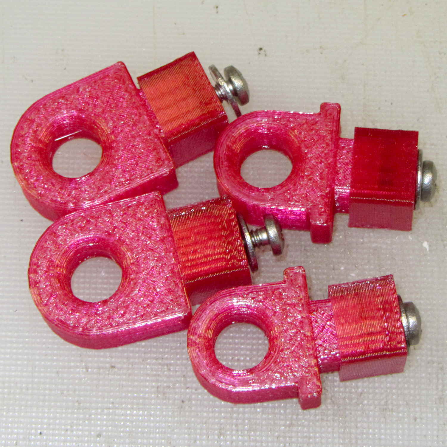
Tapping the holes for 6-32 stainless machines screws went easily enough:
Toyota Sienna hood rod pivot – PETG – assembled
She gets one of each and I keep the others for show-n-tell sessions.
The OpenSCAD source code, which differs from the original by a constant or two:
// Sienna Hood Rod Pivot
// Ed Nisley KE4ZNU November 2013

//- Extrusion parameters must match reality!
//  Print with 2 shells and 3 solid layers

ThreadThick = 0.25;
ThreadWidth = 0.40;

HoleWindage = 0.2;

Protrusion = 0.1;			// make holes end cleanly

inch = 25.4;

function IntegerMultiple(Size,Unit) = Unit * ceil(Size / Unit);

//----------------------
// Dimensions

ShellOD = 20.0;
ShellID = 8.75;
ShellLength = 10.0;

TaperLength = 1.5;
TaperID = 11.4;

BaseWidth = 20.0;
BaseThick = 3.0;

PegSide = 9.5;					// mounting peg through sheet metal
PegLength = 7.0;
PegCornerTrim = 0.75;
PegHoleOD = 0.107*inch;			//  6-32 tap hole

PegTrimSide = sqrt(2)*PegSide - PegCornerTrim;

ClampWall = 3.0;				// clamping cap under sheet metal
ClampHoleOD = 0.150*inch;		//  6-32 clearance hole
ClampCap = 3.0;					// solid end thickness

PanelThick = 2.0;				// sheet metal under hood

NumSides = 6*4;

//----------------------
// Useful routines

module PolyCyl(Dia,Height,ForceSides=0) {			// based on nophead's polyholes

  Sides = (ForceSides != 0) ? ForceSides : (ceil(Dia) + 2);

  FixDia = Dia / cos(180/Sides);

  cylinder(r=(FixDia + HoleWindage)/2,
           h=Height,
	   $fn=Sides);
}

module ShowPegGrid(Space = 10.0,Size = 1.0) {

  Range = floor(50 / Space);

	for (x=[-Range:Range])
	  for (y=[-Range:Range])
		translate([x*Space,y*Space,Size/2])
		  %cube(Size,center=true);

}

//----------------------
// Build it

//ShowPegGrid();

// pivot

translate([-ShellOD,0,0])
	difference() {
		union() {
			cylinder(r=ShellOD/2,h=ShellLength,$fn=NumSides);		// housing
			translate([-ShellOD/2,0,0])								// filler
				cube([ShellOD,(ShellOD/2 + BaseThick),ShellLength],center=false);
			translate([0,(ShellOD/2 + BaseThick/2),ShellLength/2])	// foot
				cube([BaseWidth,BaseThick,ShellLength],center=true);

			translate([0,											// peg
						(ShellOD/2 + PegLength/2 + BaseThick - Protrusion),
						PegSide/2])
				intersection() {
					cube([PegSide,(PegLength + Protrusion),PegSide],center=true);
					rotate([0,45,0])
						cube([PegTrimSide,2*PegLength,PegTrimSide],center=true);
				}
		}

		PolyCyl(ShellID,ShellLength,NumSides);		// central hole

		translate([0,0,-Protrusion])				// end bevels
			cylinder(r1=TaperID/2,r2=ShellID/2,h=(TaperLength + Protrusion),$fn=NumSides);
		translate([0,0,(ShellLength + Protrusion)])
			rotate([180,0,0])
				cylinder(r1=TaperID/2,r2=ShellID/2,h=(TaperLength + Protrusion),$fn=NumSides);

		translate([0,0,PegSide/2])					// screw tap hole
			rotate([-90,0,0])
				PolyCyl(PegHoleOD,(ShellOD + BaseThick + PegLength),6);

	}

// anchor cap

translate([2*PegSide,0,0])
	difference() {
		translate([0,0,(PegLength + ClampCap)/2])					// overall shape
			cube([(PegSide + ClampWall),(PegSide + ClampWall),(PegLength + ClampCap)],center=true);
		translate([0,0,(PegLength/2 + ClampCap + Protrusion)])		// peg cutout
			cube([(PegSide + ThreadWidth),(PegSide + ThreadWidth),(PegLength + Protrusion)],center=true);
		translate([0,0,-Protrusion])								// screw clearance
				PolyCyl(ClampHoleOD,2*PegLength,6);
	}
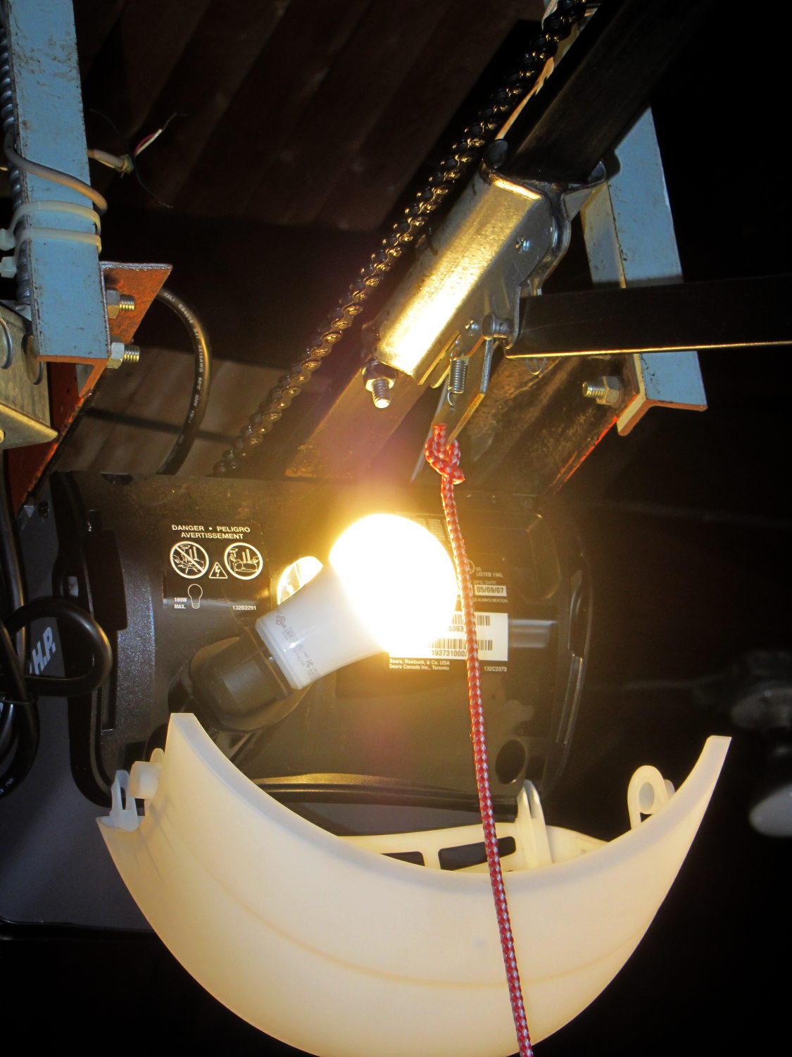
The garage door opener just ate another rough-duty bulb, so let’s see how a $7 LED bulb fares:
Walmart 60 W LED Bulb – garage door opener
It has no external heatsink fins and the color temperature looks just like the old-school incandescent bulb it’s replacing, so they’re getting a clue about what’s acceptable to ordinary folks.
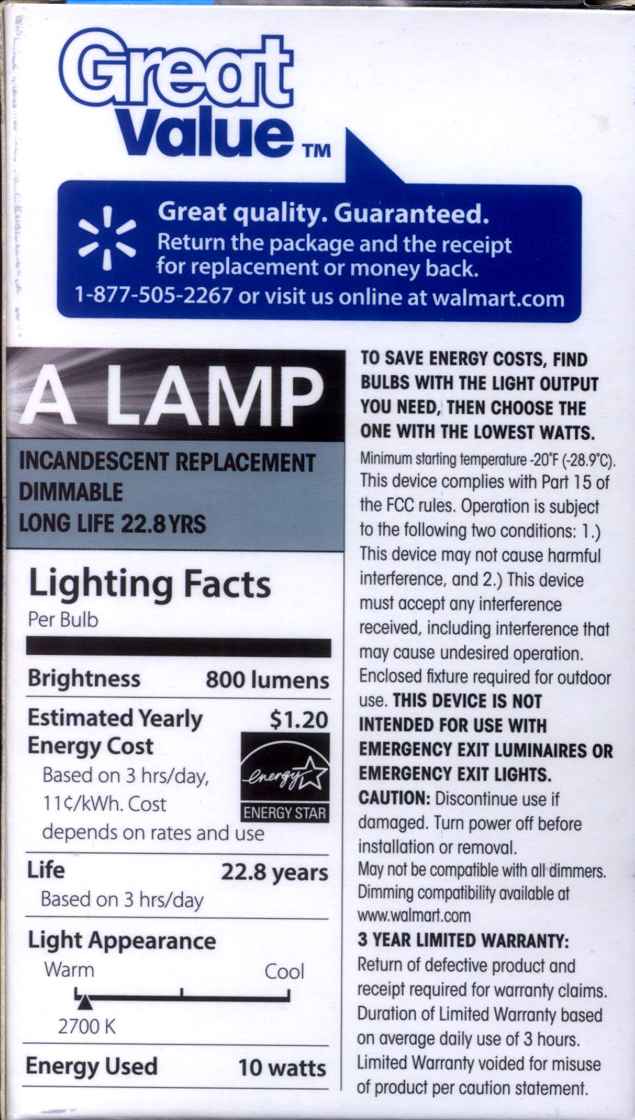
That’s equivalent to a 60 W incandescent bulb, too, at least according to the package:
Walmart 60 W LED Bulb – package data
I love the “Return the package and reciept for replacement or money back” part…
Mary gets books-on-CD at the annual library book sale, but she’s found they’re easier to use in MP3 format. We regard format transformation for our own use as covered by the First Sale Doctrine and Fair Use, but, obviously, various legal opinions differ.
I use Asunder to rip audio CDs, although it doesn’t handle non-recoverable errors very well at all. Wiping the offending disc with nose oil or ripping from a different drive will resolve most of the issues, but a recent acquisition had a nasty circumferential scratch in the middle of Track 7 that just didn’t respond to Black Magic.
CDparanoia can rip portions of a track, so a little binary search action extracts the usable data from Track 7:
cdparanoia "7-7[4:35]" Track7a.wav
cdparanoia III release 10.2 (September 11, 2008)

Ripping from sector  177155 (track  7 [0:00.00])
	  to sector  197780 (track  7 [4:35.00])

outputting to Track7a.wav

 (== PROGRESS == [                              | 197780 00 ] == :^D * ==)

Done.

cdparanoia "7[5:30]-7" Track7b.wav
cdparanoia III release 10.2 (September 11, 2008)

Ripping from sector  201905 (track  7 [5:30.00])
	  to sector  208894 (track  7 [7:03.14])

outputting to Track7b.wav

 (== PROGRESS == [                              | 208894 00 ] == :^D * ==)

Done.
With that in hand, you import the two WAV files into Audacity with a five second gap between them, drop two seconds of A-440 sine wave in the gap, and export to MP3.
The M3U playlist entry has the track time in seconds, so I hand-carved that entry to match the abbreviated length: