Ed Nisley's Blog: Shop notes, electronics, firmware, machinery, 3D printing, laser cuttery, and curiosities. Contents: 100% human thinking, 0% AI slop.
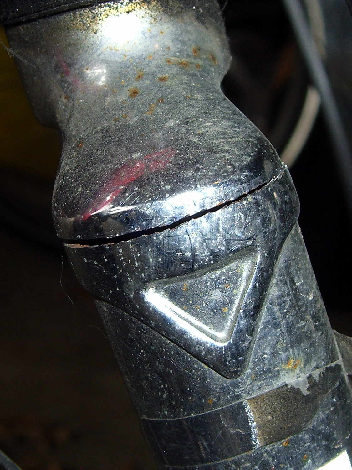
The fairing on my Tour Easy started making unusually loud booming sounds while we were out on an errand, so when we got home I poked around the front end to see what had worked itself loose. I finally managed to produce the sound, which turned out to be due to a very small motion in the fork:
Cracked Tour Easy Fork
That’s after 14 years and maybe 30,000 miles, so I’d say it did pretty well, all things considered.
On an upright bike a front fork failure kills you: the broken blade rotates forward, jams into the ground, and flips you over the handlebars. I rode about 8 miles with a broken fork and nothing exciting happened.
The Tour Easy’s design dates back to the mid-1970s, when custom bike parts weren’t readily available, and the front fork seems sized for 26 inch tires. A tubular bridge welded across just over the 20 inch (37-406) tire provides a fender mount, stiffens the blades, and, in my case, acts as a second bridge. On my bike, the fork supports the polycarbonate fairing and the Phil Wood hub provides an absolutely rigid connection between the blade dropouts.
For reference, the headset uses J.I.S 1 inch dimensions, with a 27.0 mm ID crown bearing. The stack height runs around 35 mm, but I don’t know the head tube ID.
A pair of forks are on their way; I’ll replace the one on Mary’s bike before it fails…
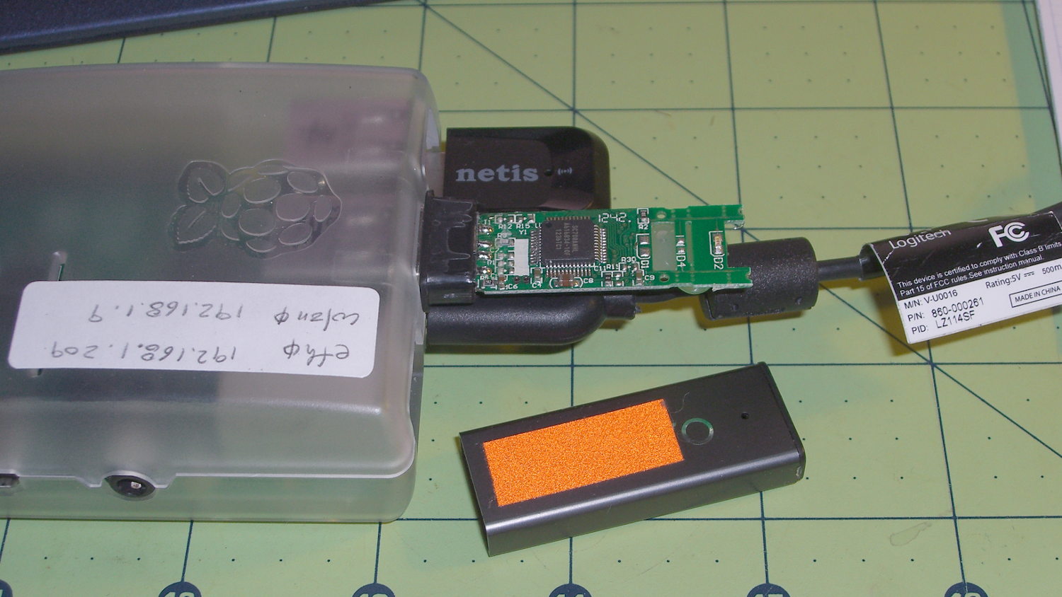
Turns out the only thing holding that case in place was a blob of hot-melt glue on the bottom of the PCB. Hot-melt glue doesn’t bond well to anodized aluminum, the RPi had been sitting outside on a winter day taking time-lapse bird feeder pictures, and the USB connector seemed a bit more snug than usual.
So I slobbered more hot-melt glue on the end of the PCB, jammed the case back in place, and that was that.
The PCB has two snap lines to accommodate shorter cases, with corresponding activity LED locations; it seems I got the long-case version.
It turns out my fancy Dell U2711 landscape monitor doesn’t work well with Displayport video. I normally leave it in power-save mode, with the power LED slowly fading orange, but about once a week it won’t start up when I turn on the PC. It seems the only solution is a hard power cycle, so I plugged it into a remotely switched outlet to eliminate having to pull its plug.
Now that I know what to watch for, it’s easy to work around: if the power LED doesn’t turn blue when the PC power goes on, immediately turn off the PC power and power-cycle the U2711. If I let the PC continue in Xubuntu, the U2713 portrait monitor becomes the primary display and X helpfully rearranges the video configuration around the disabled U2711 until I manually un-wedge things. If I shut down the PC while it’s still displaying the BIOS intro screen, then click-click the remote power switch, the U2711 will be good for another week or so.
Every month or so, the U2711 won’t light up after going into power-save mode, even though the PC is still running just fine. I set Lightlocker (which replaces the classic screensaver on Xubuntu) to blank the screen after 10 minutes and turn off the display power after 11 minutes. When the U2711 doesn’t light up, some delicate xrandr surgery through the U2713 will bring the U2711 back to life.
The starting situation looks like this:
xrandr
Screen 0: minimum 8 x 8, current 1440 x 2560, maximum 16384 x 16384
DP-0 disconnected primary (normal left inverted right x axis y axis)
DP-1 disconnected (normal left inverted right x axis y axis)
DP-2 connected (normal left inverted right x axis y axis)
   2560x1440      60.0 +
   1920x1200      59.9
   1920x1080      60.0     59.9     50.0     24.0     60.1     60.0     50.0
   1680x1050      60.0
   1600x1200      60.0
   1280x1024      75.0     60.0
   1280x800       59.8
   1280x720       60.0     59.9     50.0
   1152x864       75.0
   1024x768       75.0     60.0
   800x600        75.0     60.3
   720x576        50.0     50.1
   720x480        59.9     60.1
   640x480        75.0     59.9     59.9
DP-3 connected 1440x2560+0+0 left (normal left inverted right x axis y axis) 597mm x 336mm
   2560x1440      60.0*+
   1920x1200      59.9
   1920x1080      60.0     59.9     50.0     24.0     60.1     60.0     50.0
   1680x1050      60.0
   1600x1200      60.0
   1280x1024      75.0     60.0
   1280x800       59.8
   1280x720       60.0     59.9     50.0
   1152x864       75.0
   1024x768       75.0     60.0
   800x600        75.0     60.3
   720x576        50.0     50.1
   720x480        59.9     60.1
   640x480        75.0     59.9     59.9
Note that there’s no asterisk on DP-2’s 2650x1440 entry, which means it’s not active. In fact, it’s jammed in power-save mode and nothing other than a hard power cycle will wake it up.
The U2713 portrait monitor wakes up just fine, so X piles all the program windows into an untidy heap on that display, but, with enough Alt-Tab action, I can eventually resurface the console window and start typing:
The DP-2 and DP-3 outputs correspond to what xrandr reported above.
Then I must rearrange all the windows on both monitors again, but that’s much easier than the hocus-pocus required to recover after rebooting the PC with the U2711 shut down.
The normal (or recovered) video situation looks like this:
xrandr
Screen 0: minimum 8 x 8, current 4000 x 2560, maximum 16384 x 16384
DP-0 disconnected primary (normal left inverted right x axis y axis)
DP-1 disconnected (normal left inverted right x axis y axis)
DP-2 connected 2560x1440+0+0 (normal left inverted right x axis y axis) 597mm x 336mm
   2560x1440      60.0*+
   1920x1200      59.9
   1920x1080      60.0     59.9     50.0     24.0     60.1     60.0     50.0
   1680x1050      60.0
   1600x1200      60.0
   1280x1024      75.0     60.0
   1280x800       59.8
   1280x720       60.0     59.9     50.0
   1152x864       75.0
   1024x768       75.0     60.0
   800x600        75.0     60.3
   720x576        50.0     50.1
   720x480        59.9     60.1
   640x480        75.0     59.9     59.9
DP-3 connected 1440x2560+2560+0 left (normal left inverted right x axis y axis) 597mm x 336mm
   2560x1440      60.0*+
   1920x1200      59.9
   1920x1080      60.0     59.9     50.0     24.0     60.1     60.0     50.0
   1680x1050      60.0
   1600x1200      60.0
   1280x1024      75.0     60.0
   1280x800       59.8
   1280x720       60.0     59.9     50.0
   1152x864       75.0
   1024x768       75.0     60.0
   800x600        75.0     60.3
   720x576        50.0     50.1
   720x480        59.9     60.1
   640x480        75.0     59.9     59.9
Note that DP-2 now sports an asterisk.
The width of Screen 0 covers the U2711 in landscape and the U2713 in portrait: 4000 = 2560+1440. The height comes from the U2713 in portrait mode: 2560.
That this should not be necessary goes without saying. The U2711 run with firmware revision A09, which was supposed to fix the problem, but Dell basically walked away from it.
I’m pretty much forced to use Displayport video for both monitors, as a low-profile nVidia card with twodual-link DVI-D outputs doesn’t seem to exist. The Dell Optiplex 980 disables the system board video when it finds a PCI-E video card, so there’s no way to run the U2713 from the system board Displayport and the U2711 from a dual-link DVI PCI-E video card.
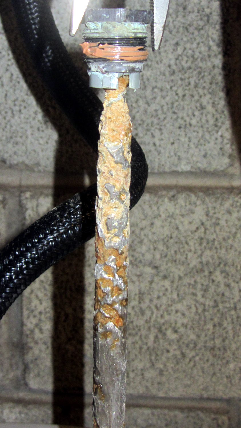
But, as before, most of the corrosion is close to the top end. The rest of the rod was covered with a thick mineral scale that I hammered off, then scuffed the rod with a shoe rasp to expose some metal.
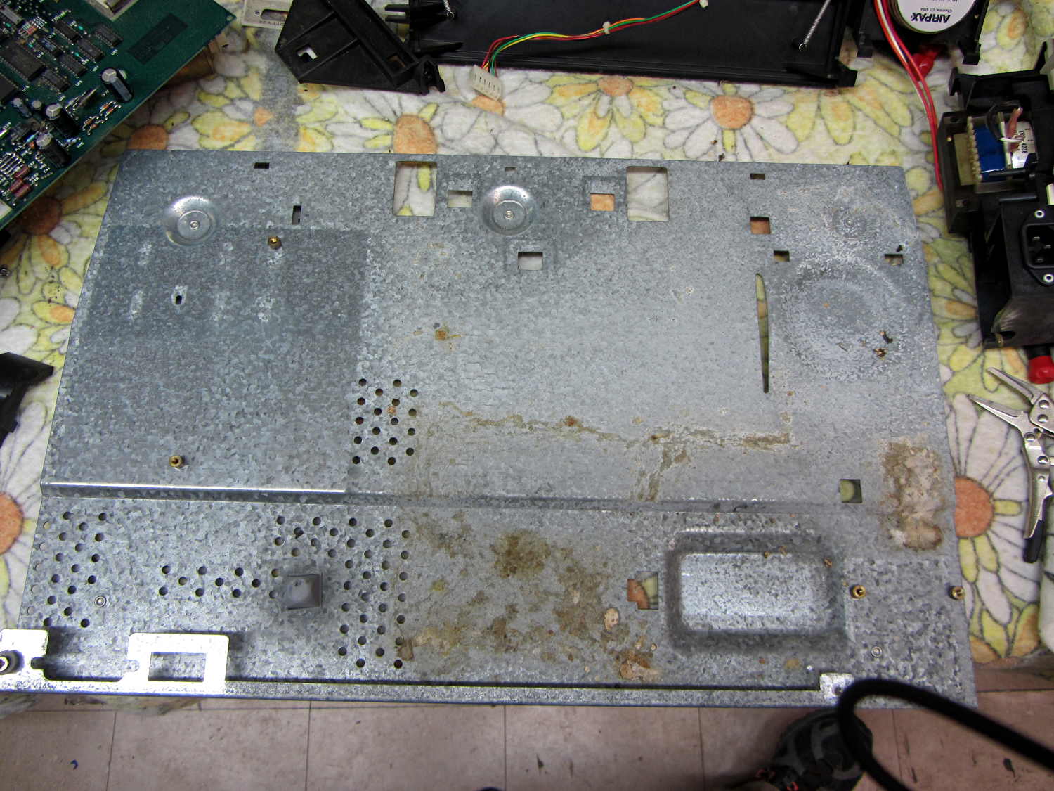
After mentioning that I wished I still had my HP 7475A plotter, Dithermaster sent me one from his heap. As he explained, a mouse family had used it as a combination hotel-granary-latrine:
HP 7475A – chassis latrine
For whatever it’s worth, if you must get a bazillion seeds out of a plotter, ship it halfway across the continent: UPS performs a lengthy three-axis vibration test that shakes all the loose bits through the vents.
You’ll probably want the original HP 7475A documentation from the (unofficial) HP Computer Museum before digging in. Not mentioned anywhere: the two washers at the rear edge of the case are not identical. The one holding the power supply in place is slightly longer than the one at the serial connector. Mine are now color-coded to their locations.
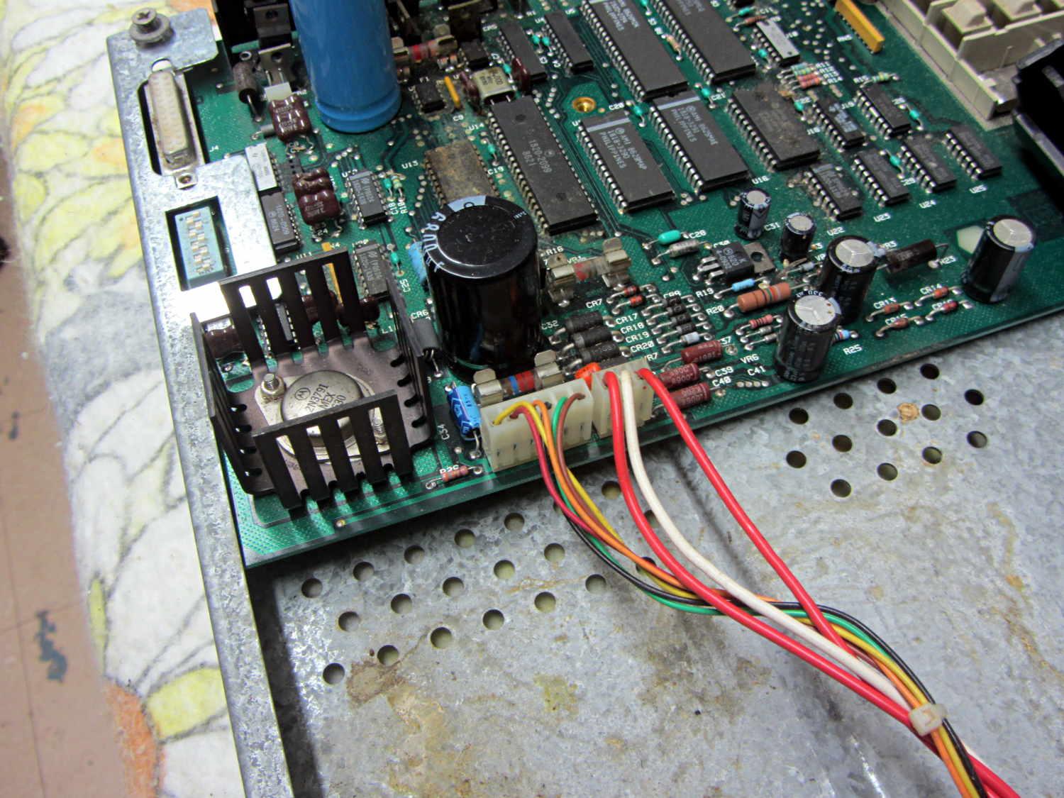
A critter whizzed on U13, the serial adapter chip, just beyond the big black filter capacitor:
HP 7475A – PCB latrine area
I rinsed everything (except, no fool I, the membrane keypad at the front of the PCB) with warm water, flushed the latrine areas with dilute baking soda (alkaline, to neutralize the urea), rinsed with hot water, blew-dry with compressed air, then let the pieces sit for a few days.
After reassembly, the plotter didn’t start up. It’s a third of a century old, what did you expect?
Measuring the electrolytic capacitors showed they were all in surprisingly good condition, with only C27 and C34 (on this Option 001 = RS-232 board) having moderately high ESR. They’re the pale blue axial caps just right of the heatsink, both 22 μF 25 V:
C27: Processor Reset timing (U14 – p. 6-27/6-28)
C34: +5 V filter cap (U21 – power supply p. 6-31)
The corresponding caps on the Option 002 = HP-IB board are C20 and C25. FWIW, if you have an HP-IB plotter, you should probably just hack an Arduino into the motor control connections and run it with Grbl; you’d get a bare-bones plotter eating G-Code, not HP-GL, but that’s not entirely a Bad Thing. Adapting the tool change code to handle the pen carousel is left as an exercise for the desperate.
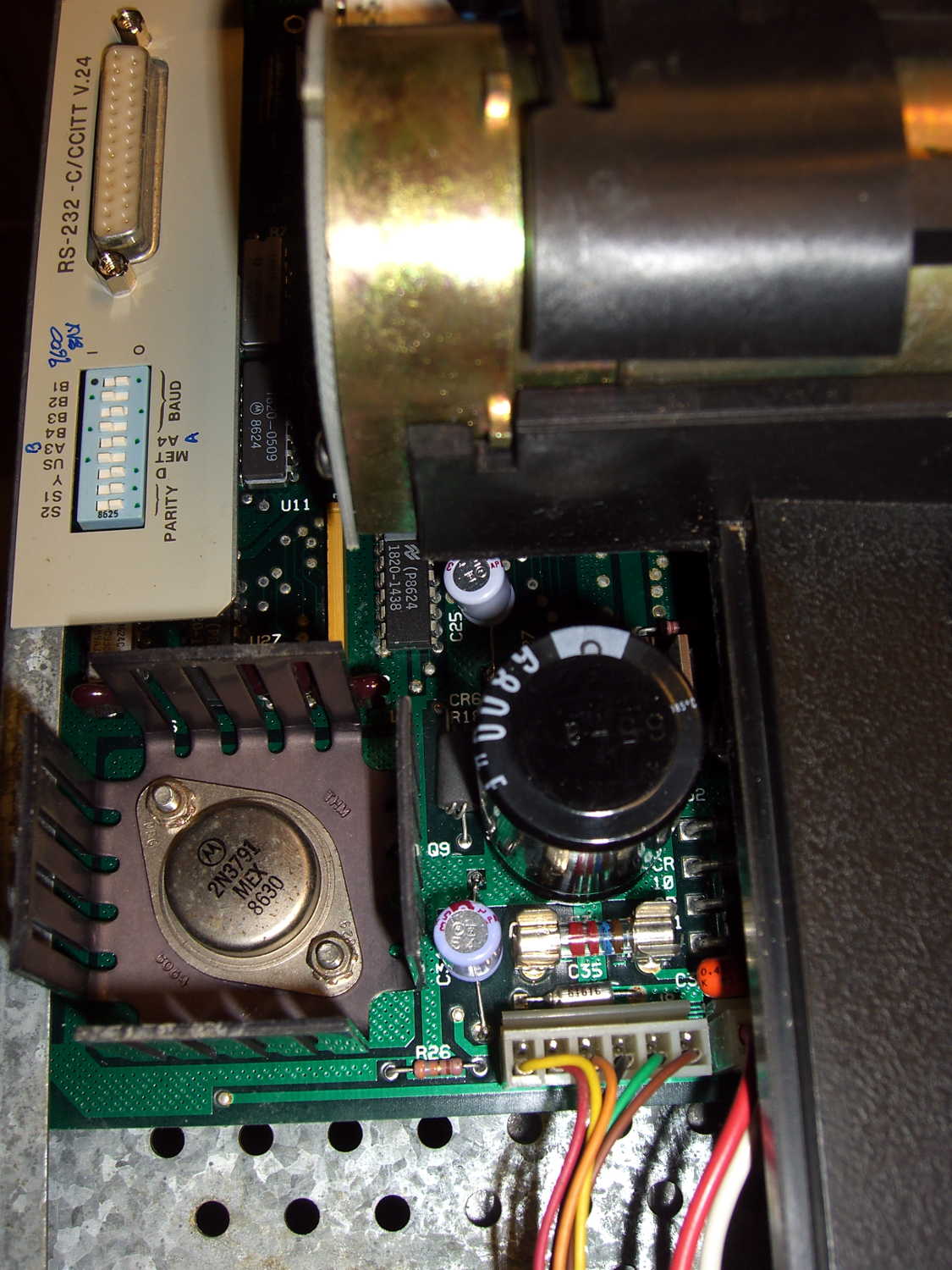
I replaced the offending caps with 33 μF 50 V radial caps from the heap:
HP 7475A – re-capped PCB
And then it performed its Demonstration Plot (load paper, hold down P1 + P2 buttons, turn on power) perfectly. The fossilized pens left no trace behind; we all expected that.
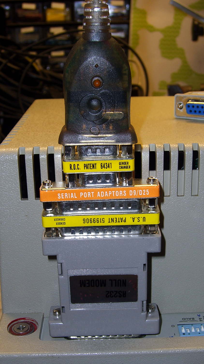
The serial port connection on the back required, from bottom to top:
All of which came from the Big Box o’ Serial Adapters and produced this rather unsteady ziggurat:
HP 7475A – serial port adapters – typical
Seeing as how I’ve been adapting serial connections since before the HP 74754A was a thing, the Adapter Box has All! The! Adapter! Genders! plusDer Blinkenlights! They don’t come in nearly as handy nowadays, though, which is a Good Thing.
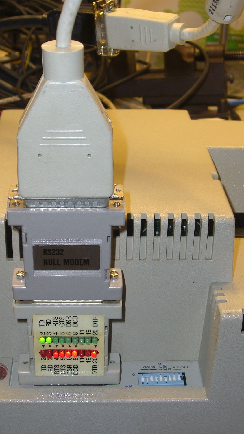
Some optimization pared down the ziggurat and added a short extension cable:
HP 7475A – serial port adapters – hardcore
Eventually, I’ll build a custom cable, but it’s good enough for now.
The switches select 9600 b/s serial data in 8N1 format. Yes, the plotter tops out at 9600 b/s, but remember we’re dealing with a pen plotter that executes terse ASCII commands. It offers both XON/XOFF and DTR/DSR hardware handshaking to prevent overruning the internal 1 kB buffer, plus a myriad other software-selectable options relevant to long-forgotten datacomm systems.
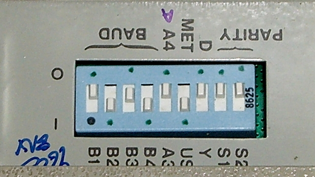
Lest I forget, dots now mark the switch settings for 9600 8N1, A (letter) paper, US (inch) units, direct serial connection:
HP 7475A – DIP switch settings
And then it Just Worked: type IN;SP1; into minicom and the plotter grabs Pen 1. The rest is a simple matter of software.
As we expected, the remaining temple of Mary’s Silhouette glasses broke, a bit over a year from the previous repair, and this repair proceeded along the same lines as the previous fix.
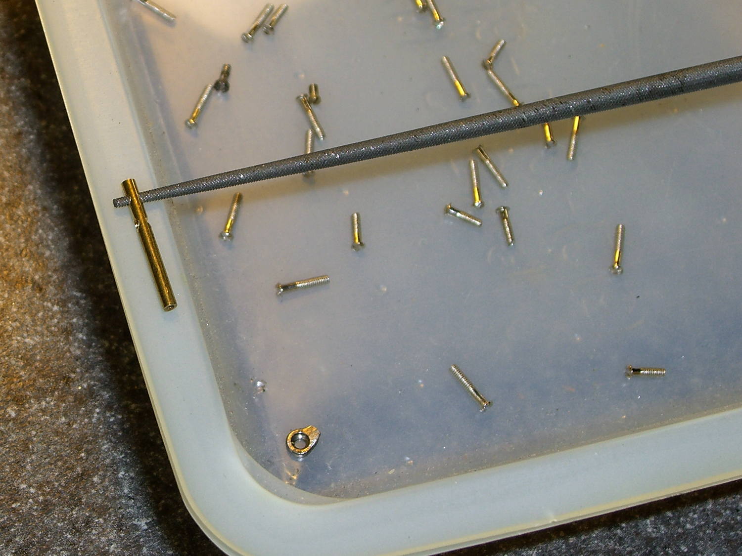
I don’t recall having to do quite this much filing to make the screws fit, but they don’t call ’em “needle files” for nothin’:
Silhouette temple repair – filing screw holes
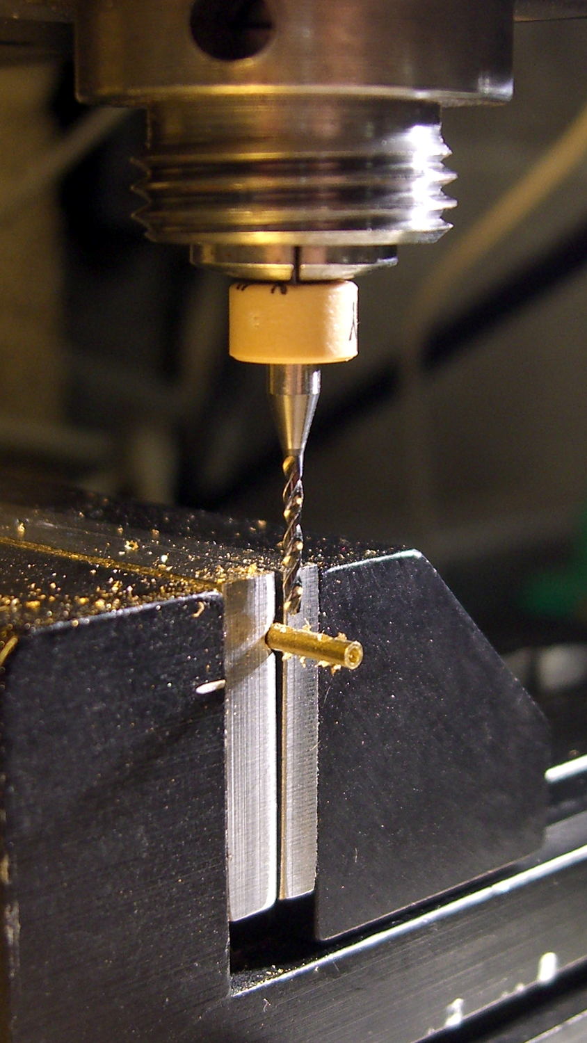
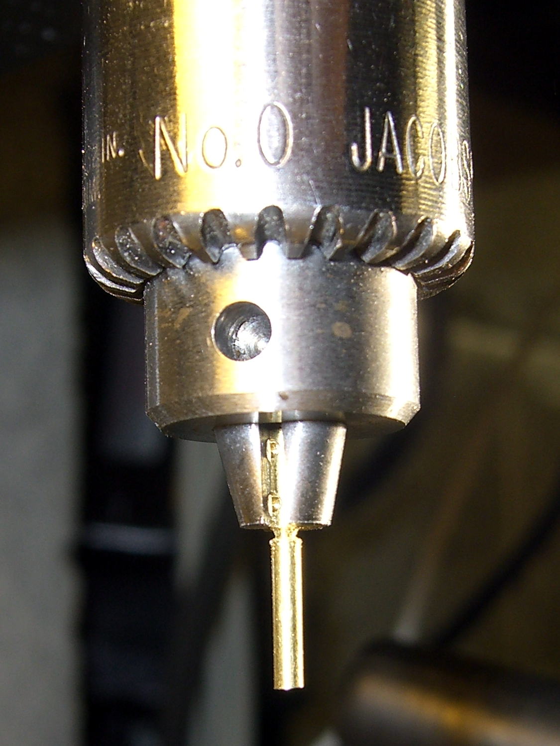
Trim the tube to the proper length by chucking it in the Sherline, rotating the spindle by hand, and filing a notch just below the jaws:
Silhouette temple repair – trimming tube
Then file the end flat, countersink it just a bit, and ream out the hole to fit the broken end of the earpiece. This one didn’t quite fit the tubing, but we’re talking a few mils of tolerance on a bent piece of titanium. Rough up the end of the earpiece, degrease everything, and a few dabs of epoxy suffice for another Steampunk repair:
Silhouette temple repair – finished
The original fix continues to hold, but … this can’t go on.
I’d originally secured the rear fender to the steel strap connecting the chainstays on Mary’s Tour Easy with a cable tie: small, simple, light weight, reliable. Unfortunately, that put the end of the fender just slightly lower than the strap and, I fear, sprayed water all over the strap, where it worked its way through a paint flaw and rusted the steel under the paint. A simple metal clip would chew its way through the pain[t] on the strap, so, seeing as how we’re living in the future…
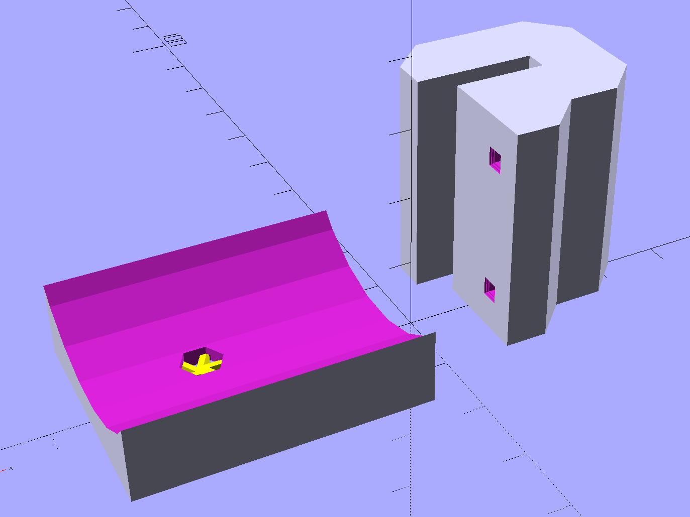
The C-shaped block on the top grips the steel cross-strap, the trough fits the fender’s curve, the little spider supports the inside of the nut recess, and a pair of alignment pin holes (one visible) help during gluing:
Tour Easy Rear Fender Bracket – solid model – show
Although it’s tempting to 3D print both parts as a single unit, laying them out like this aligns the threads for best strength in each piece:
Tour Easy Rear Fender Bracket – solid model – build
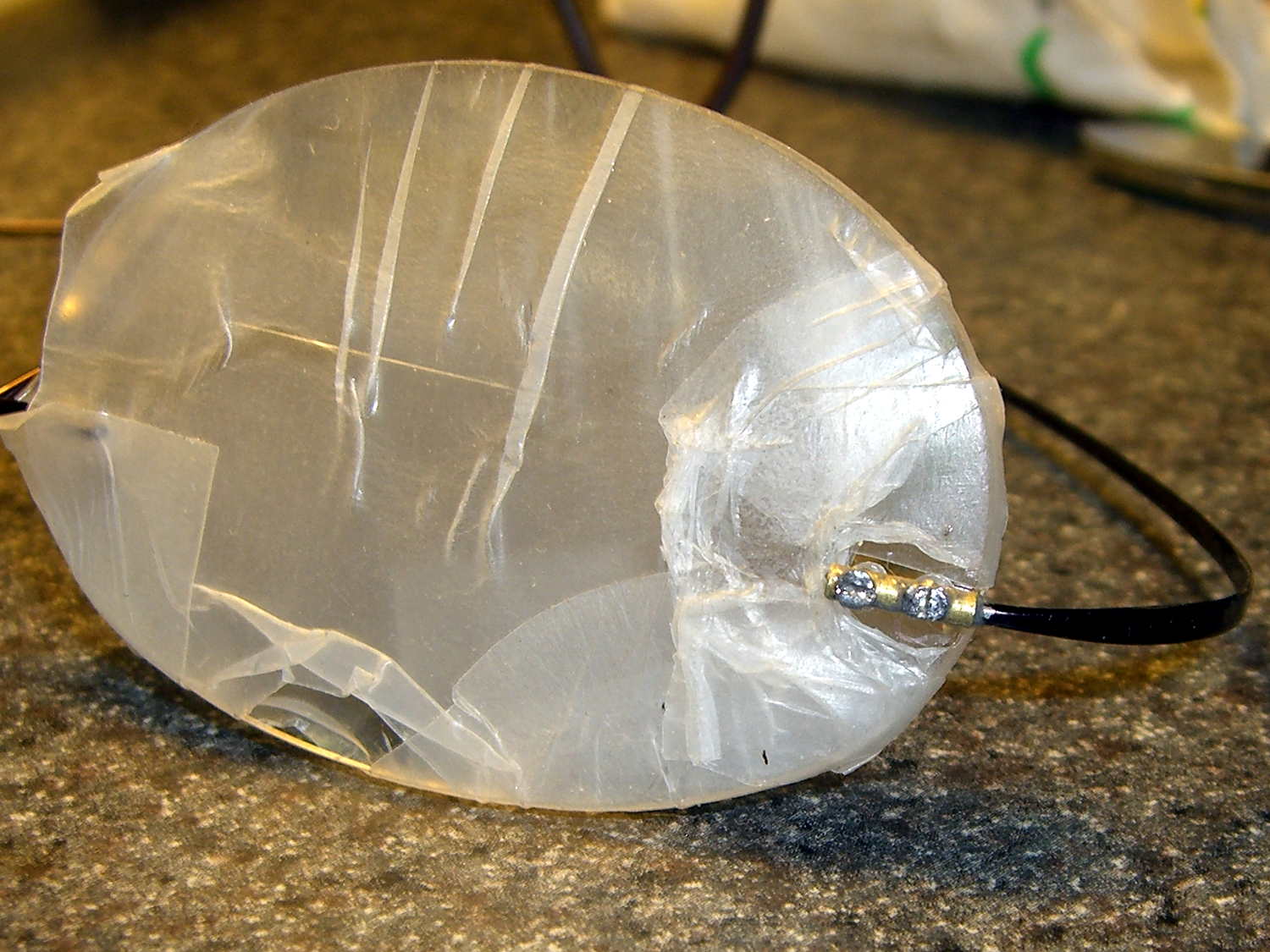
Pressing the bracket on the glass slab (flat side up, nubblies on the bottom) with the clamps in place finished the job. The slightly crushed support spider from the nut recess sits in the foreground:
Tour Easy rear fender bracket – gluing
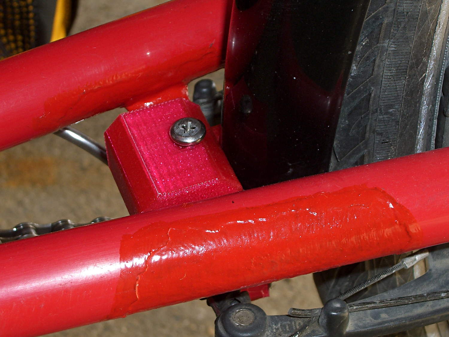
Magenta PETG matches the red Tour Easy paint surprisingly well:
Tour Easy – rear fender bracket – installed – top
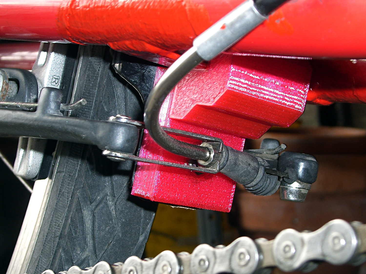
From below, you can see why the top block can’t extend all the way to the bottom of the fender mount:
Tour Easy rear fender bracket – installed
That rubber boot needs replacing in the worst possible way, but I didn’t have anything suitable on hand and wouldn’t dismount that cable even if I had; cables never go back on properly.
Alas, because the brakes weren’t mounted when I did the measurements, I had to build one to find out why a long block wouldn’t work:
Tour Easy rear fender bracket – long back
The screw atop the block (on the left in that picture) presses a small plastic slug against the steel strap, in the hopes it won’t chew through the paint quite as rapidly. The screws & nuts are stainless, so at least they’ll survive for a while.
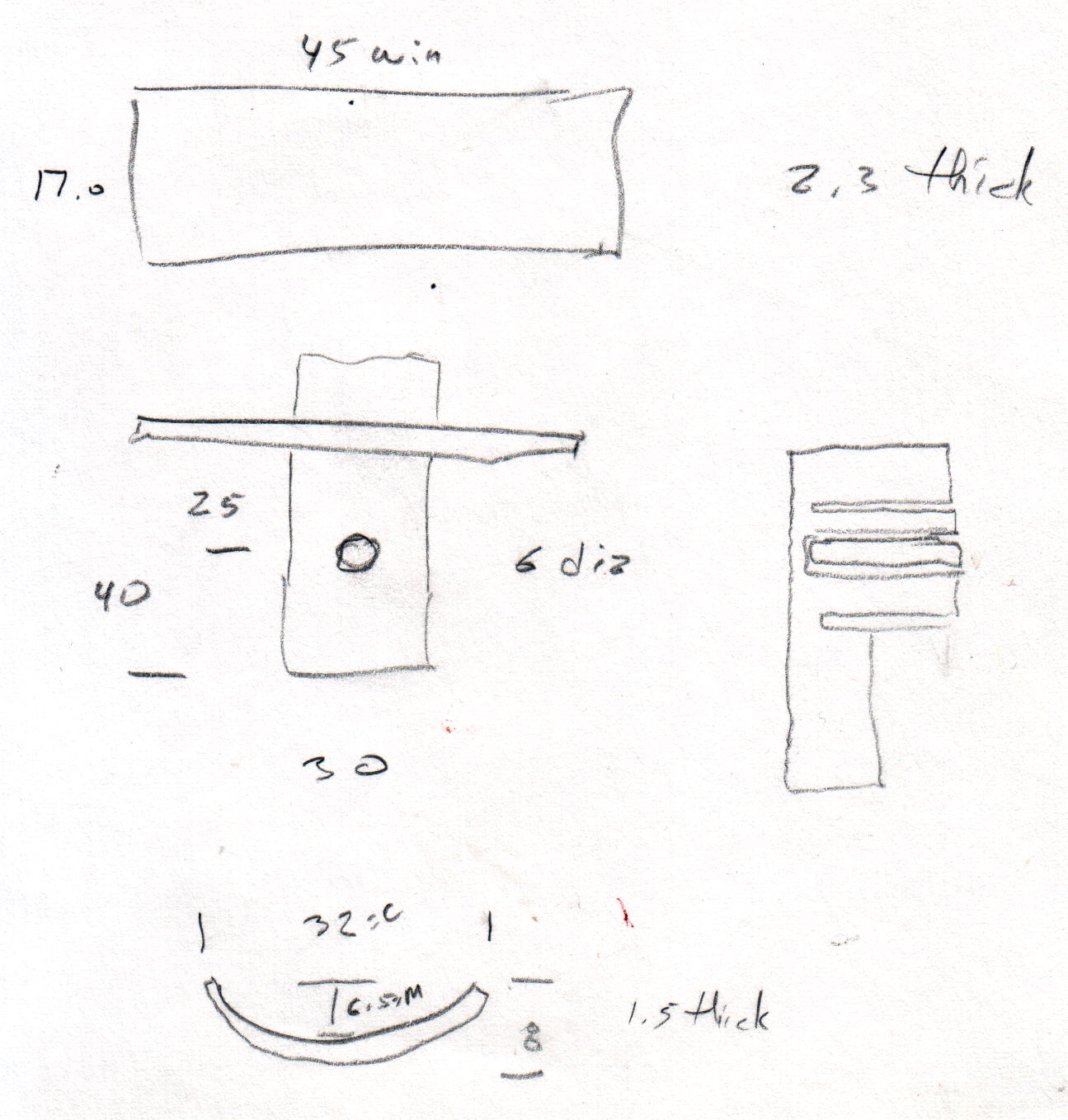
The curve in the trough comes from the chord equation applied to these crude measurements:
Tour Easy Rear Fender Bracket – measurement doodle
Fortunately, it’s tucked into a spot where nobody ever looks…