Ed Nisley's Blog: Shop notes, electronics, firmware, machinery, 3D printing, laser cuttery, and curiosities. Contents: 100% human thinking, 0% AI slop.
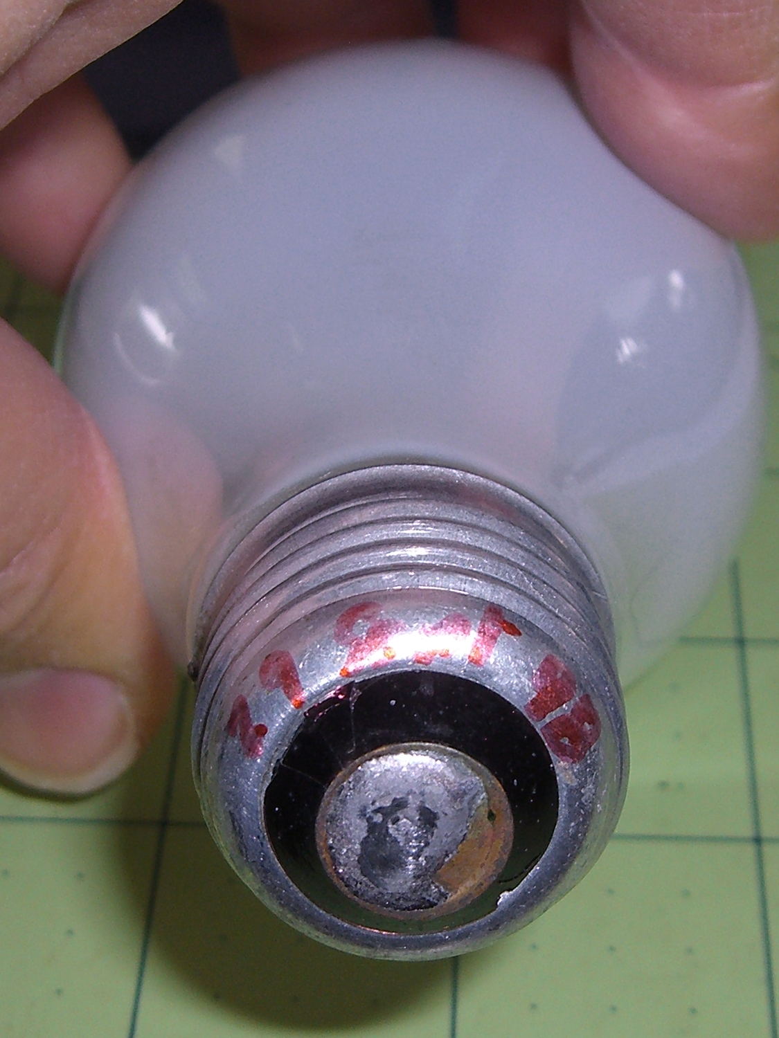
One of the four 40 W bulbs in the classic 1955 fixture over the front bathroom mirror burned out, leading to this discovery:
40 W bulb – lifetime
Yup, I installed that bulb in late September 1998, when we repainted that bathroom (for the first time since the original owners painted it in 1955). Getting a decade and a half from an incandescent bulb in regular use ain’t all that bad, sez I. Two other bulbs appeared in mid 2014, replacing bulbs with barely 6 years of service. Inexplicably, the third bulb has no date; I must be slipping.
Having burned through the 40 W bulb stash, I put two 60 W incandescents in the center sockets, leaving me with four new-old-stock bulbs on the shelf. Might be a lifetime supply for this house…
Once again, another Xubuntu desktop box started having troubles with the Gnome keyring manager, with baffling symptoms including a request for a password you don’t know and forgetting passwords you’ve entered correctly.
The solution, much as before, requires at least some of:
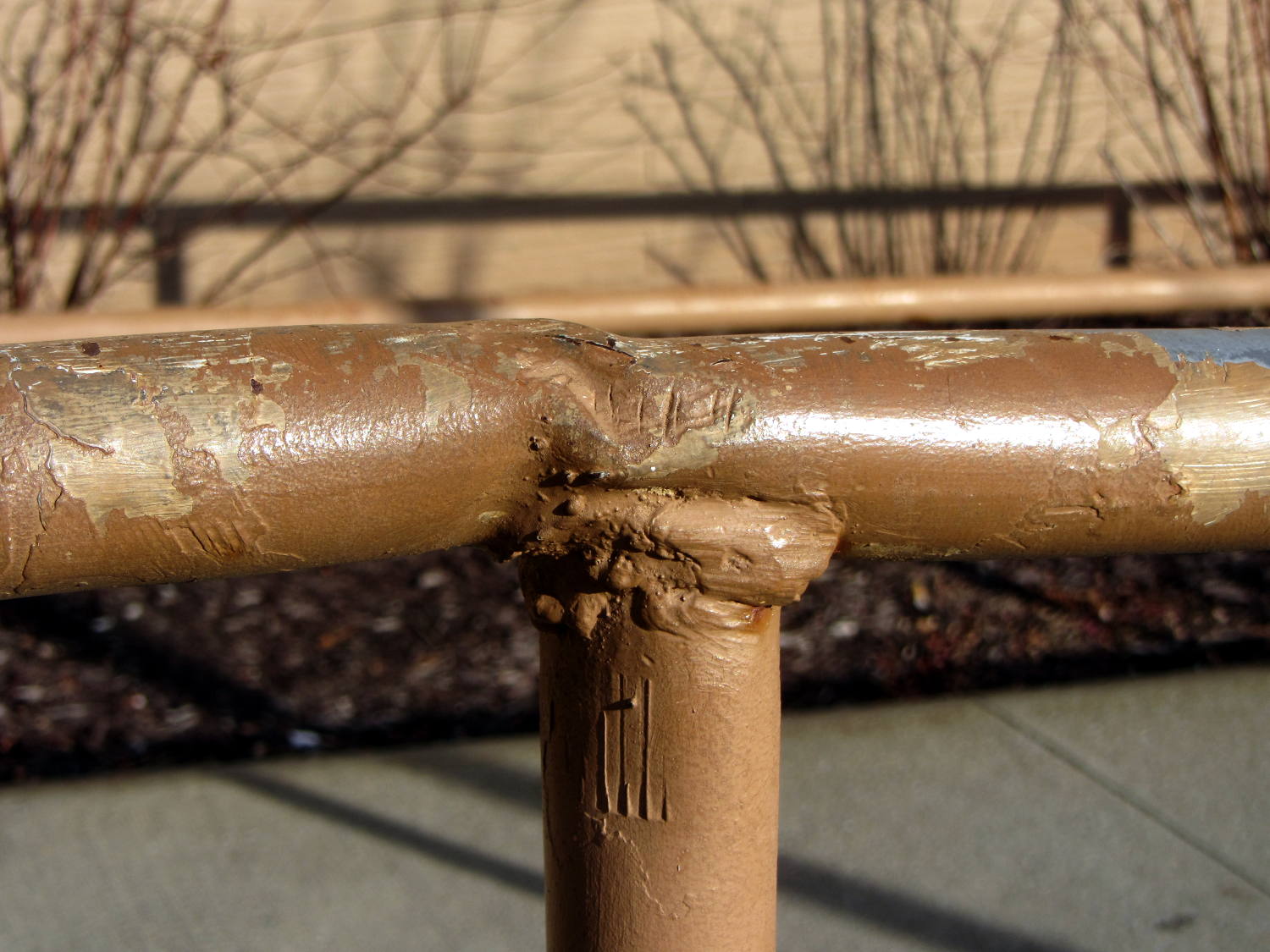
In all fairness, I don’t know how you’d weld a decent joint in a situation like that, without far more prep work than seems appropriate. There’s not much metal in those tubes for proper grinding and fishmouthing.
The handrail may not be long for this world: the bottom few inches of many posts have corroded to the vanishing point due all the salt applied to the pavement…
Even though the current has the usual exponential relationship to the terminal voltage, the slope at 200 mA (100 mA each, assuming they share & share alike) remains low enough that I (think I) can get away with just dialing in a voltage and leaving it at that; changes due to small temperature variations won’t cause meaningful differences in the current.
That’s easier than building an adjustable current regulator, anyway.
The heap disgorged two cheap DC-to-DC boost converters from halfway around the planet, with about the right specs:
So I wired one up to the bench supply, set it for 12 V, turned it on, and wham it maxed out the supply at 3 A with no load on the converter’s output.
Huh.
Adding a suitable load resistor brought the input current down, but the voltage adjustment trimpot didn’t have much effect and the bench supply would still wham hit 3 A with no provocation, so the load resistor didn’t actually make any difference. Eventually, I figured out that simply pressing my finger on the trimpot caused the output to vary wildly.
Given that fairly broad hint, this became obvious:
Boost Converter – trimpot pins
Evidently, I had used the other converter for the previous tests. Huh.
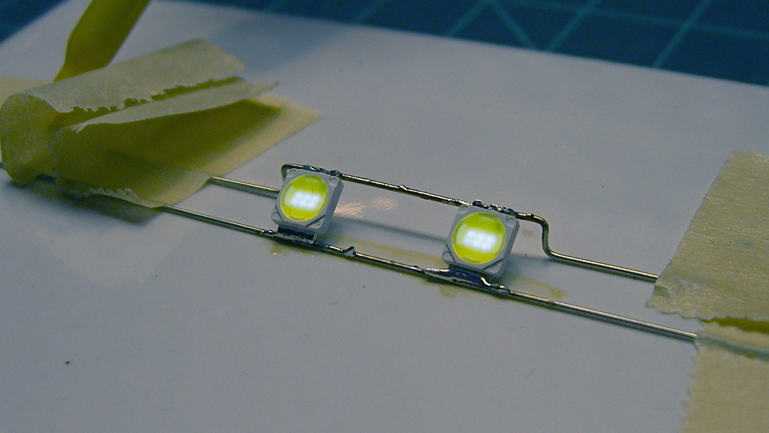
With that trimpot pin soldered in place, the converter worked fine. Eyeballometrically speaking, the LEDs seem bright enough at 100 mA total (50 mA each) for my purposes, which happens at 18-ish V. Dissipating only 2 W won’t require nearly as much heatsink as they’re presently mounted on, although I should wait for warmer weather before concluding that they’re doing OK while crammed inside the end cap.
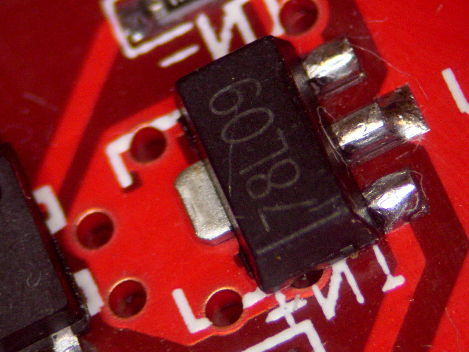
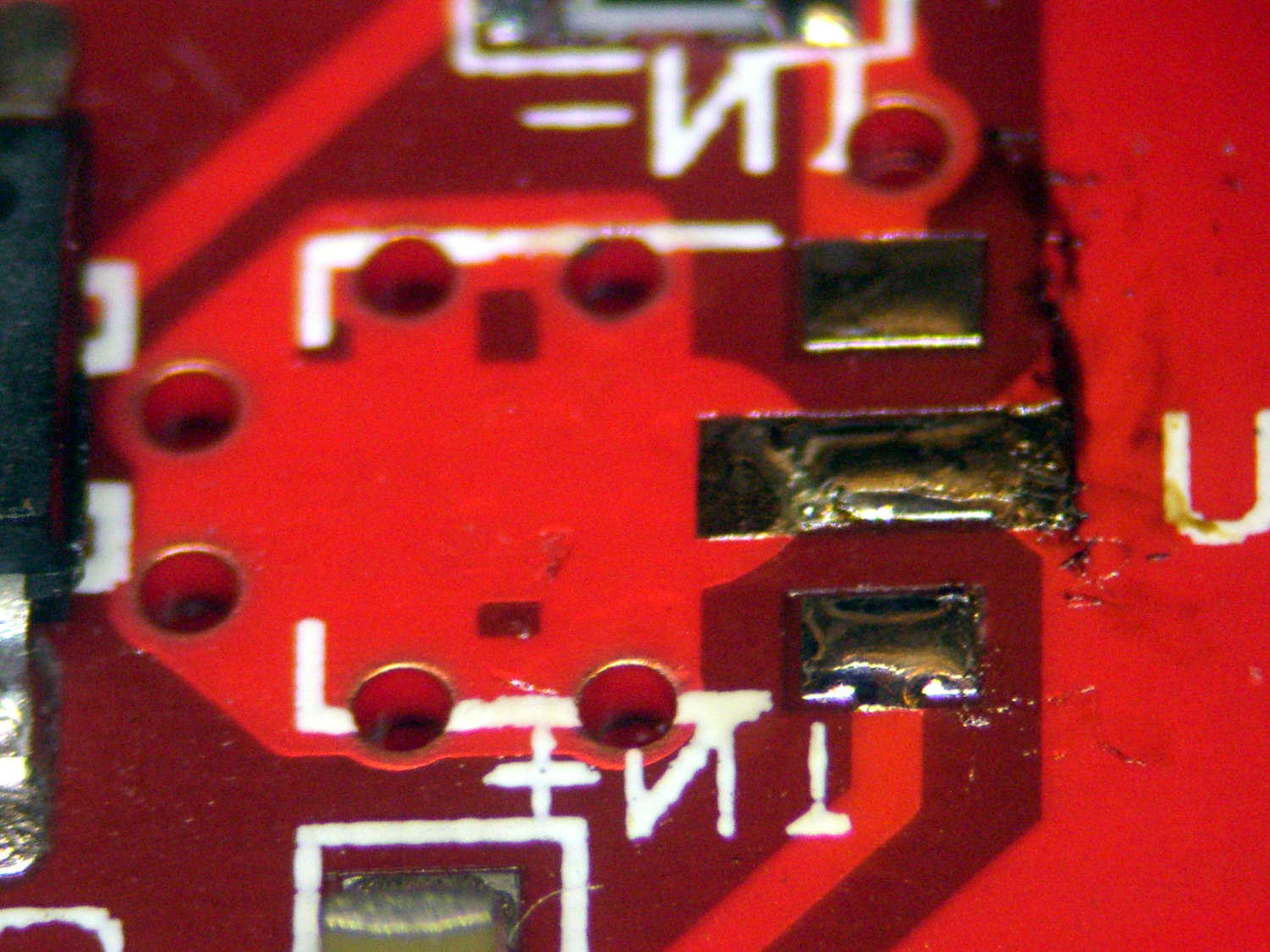
Before declaring victory, I took a closer look at the board and found this mmm oversight:
Boost Converter – masked 78L09 tab
Notice the big pad under the 78L09 regulator, with six thermal vias to an expansive copper pour on the other side of the board, completely covered with red solder mask.
Removing the regulator show the regulator’s footprint didn’t include the tab:
Boost Converter – 78L09 footprint
Maybe they decided, after a careful analysis, that the regulator couldn’t possibly dissipate enough power to warrant the additional solder required for the entire thermal pad. Heck, pocket a fraction of a yuan on ten million boards and you’re livin’ large.
Scraping the mask off, fluxing everything in sight, and soldering the regulator down probably won’t make any difference:
Boost Converter – scraped and soldered
Yes, The Bigger The Blob, The Better The Job strikes again. It does make me feel better and that’s all that counts.
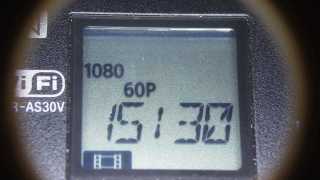
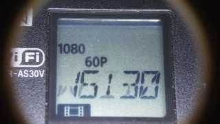
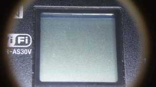
So one of my Genuine Sony 64 GB MicroSDXC cards stopped working in my Genuine Sony HDR-AS30V action camera, failing to record video after starting normally.
For example:
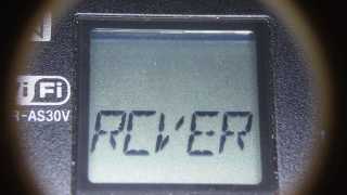
The RCVER status display doesn’t appear anywhere in the manual, but also occurs when the camera must rebuild its metadata indexes. Or something like that. Anyhow, it’s obviously unhappy about what just happened in the course of recording.
After several weeks of having Sony ignore my emailed requests (no “email agent” never contacted me after the initial “we’re on it” autoreplies) and after several days of being blown off by their phone menu (800-222-7669 and 800-282-2848 lead to the same tree, after which 5 – 1 – 6 disconnects after one ringy dingy), I got another number by picking a reasonable (to me) option and bulldozing the pleasant voice off-script: 877-440-3453. It turns out that if you’re at the Digital Camera node in the Sony tech support tree, the helpful agent cannot find the model number of the SR-64UY MicroSDXC card in their database, even though I’m looking at the Sony Support web page describing it.
Anyhow, 877-440-3453 (or the “direct” 956-795-4660) produces a pleasant voice that directs me to their Media Services center in Texas and, after clicking on the Ordering Information menu item (isn’t that obvious?), produces a PDF that one fills in and sends with the failed media for their perusal.
Being that type of guy, I sent in a somewhat more extensive description than would fit in the tiny space on the form:
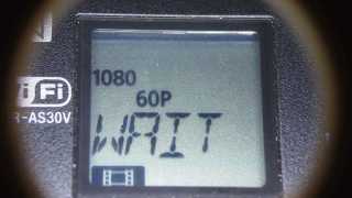
The problem with this SR-64UY MicroSDXC card (serial N73WAXOP) is that it cannot record video at the highest resolution produced by my SONY HDR-AS30V action camera: 1920x1080p @ 60 fps.
The formatted data capacity seems unchanged at 59 GB, so the problem is not a loss of capacity.
The camera starts recording and will continue for a few seconds or a few minutes, at which point it stops recording, flashes WAIT, then RCVER (“recover”), then returns to its idle mode. The recorded video is correct up to the failure.
I have reformatted the card in the camera, which does not correct the problem.
An identical SR-64UY MicroSDXC card (serial N73WA9JM), bought shortly afterward and not used, continues to operate correctly, so the problem isn’t the fault of the camera.
The failing card (XOP) has recorded less than 100 sessions since August, while the working card (9JM) has been sitting, unused, on my desk. Recording sessions generally run 45 to 90 minutes and the AS30V produces a 4 GB every 22 minutes, so each session involves 2 to 6 large video files, plus the same number of thumbnails. I transfer the files to a PC and delete them from the card after each session. The card has therefore recorded only 1000 GB of video before failing.
The XOP card can record video at 1920×1080 @ 30 fps and all lower resolutions. The camera requires a Class 4 speed, which means that the SR-64UY card no longer meets its Class 10 / U 1 speed rating.
Please replace this card with one that meets its speed rating.
Thank you…
The replacement card just arrived, so a speed reduction is a warranty failure.
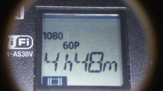
I’ll test this one by plugging it into the high-amperage Micro-USB charger for the Kindle, aiming it at a clock, and letting it run until it’s either filled the card with excruciatingly boring high-data-rate video or crashed & burned in the attempt.
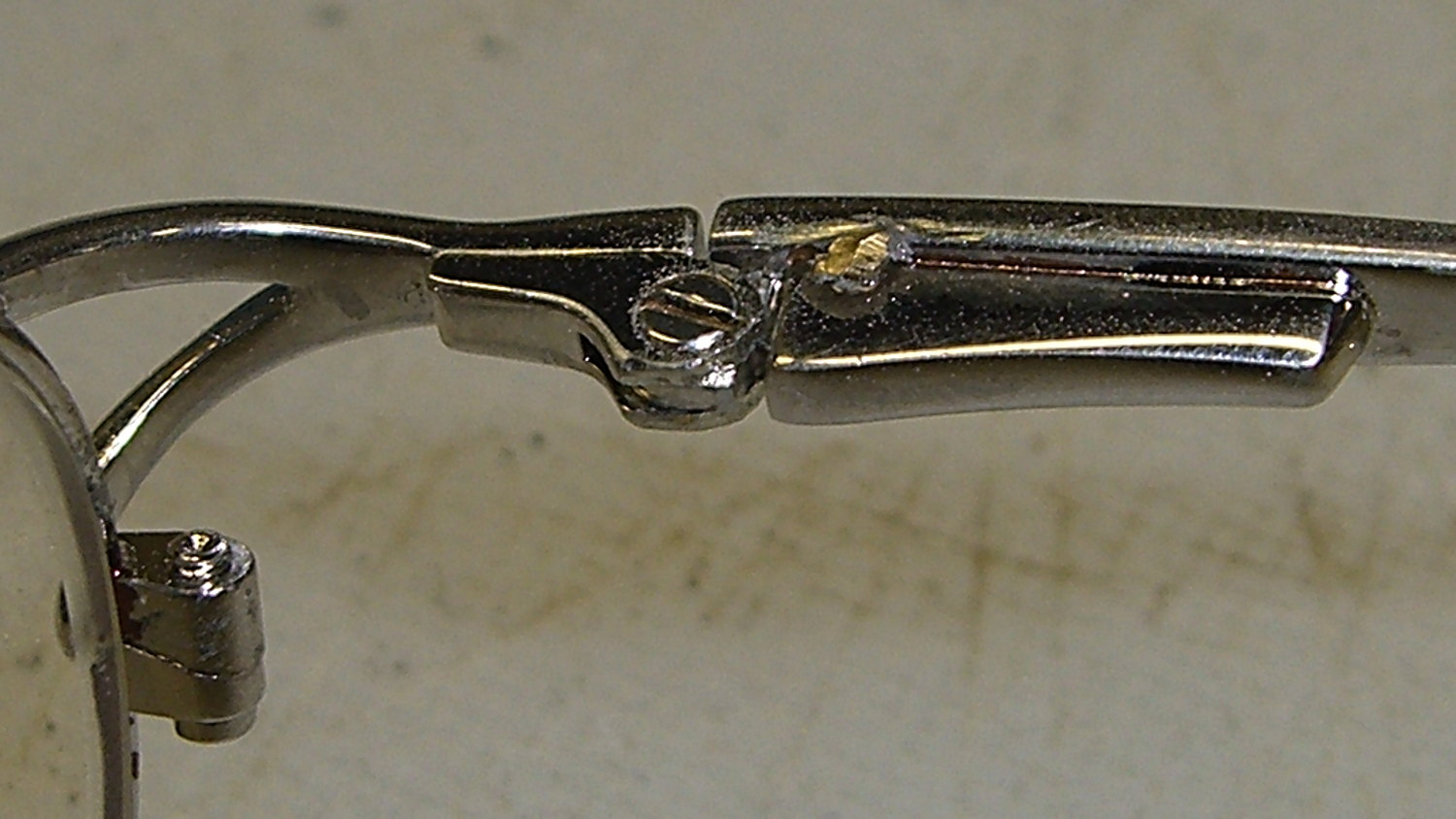
Unfortunately, the smooth interior of the temple spring pocket and the smooth exterior of the hinge plate didn’t provide enough mechanical lock for the epoxy; the pieces pulled apart after a week.
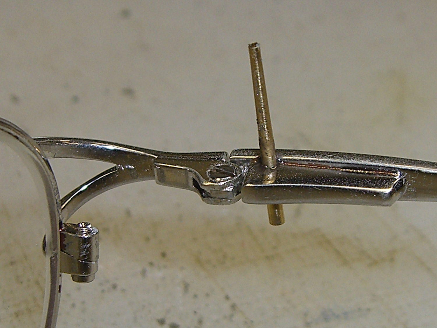
So I put a stake in its heart:
Eyeglass temple – tapered pin
That’s a tapered brass pin from the Box o’ Clock Parts, buttered up with a dab of epoxy, then shoved firmly into a 41 mil (#59) hole drilled through the pocket and the edge of the hinge plate.
Fast-forward overnight, apply a Dremel grinding bit, and it looks passable:
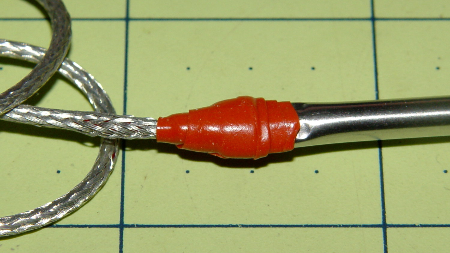
The replacement probe has a woven metal jacket that’s allegedly more rugged than the original plastic, but I think the main difference comes from the additional strain relief at the end of the probe:
Kitchen thermometer – new probe
That still looks abrupt to me, so I wrapped a silicone tape snippet around the joint:
Kitchen thermometer – new strain relief
Probably not food-safe, definitely butt-ugly, but I don’t want to replace the probe again for a long time.
FWIW, although the probe description says it’s compatible with Taylor 1970N thermometers and doesn’t mention the 1478 we have, the 2.5 mm plug fits (no suprise there) and the display shows appropriate temperatures; it seems no less accurate than the original probe.