The Smell of Molten Projects in the Morning

Ed Nisley's Blog: Shop notes, electronics, firmware, machinery, 3D printing, laser cuttery, and curiosities. Contents: 100% human thinking, 0% AI slop.

Tag: MPCNC

Pimping and using a Mostly Printed CNC Machine

  • MPCNC: Diamond Drag Engraving Speed Tests

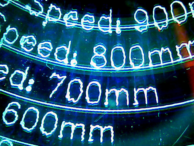
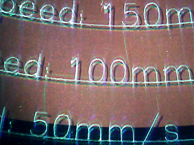
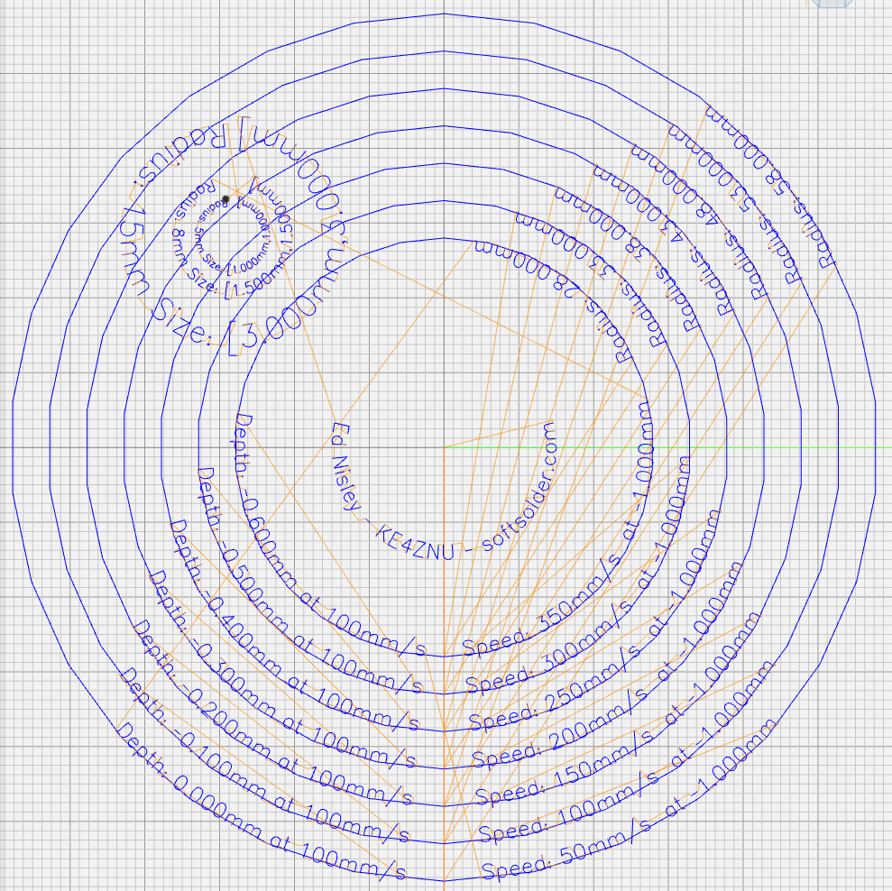
    The MPCNC isn’t the most stable of CNC machine tools, given its large masses and 3D printed structure. My early plotting pen tests suggested speeds around 250 mm/min were appropriate:

    MPCNC - GCMC Text - 250 mm-min
    MPCNC – GCMC Text – 250 mm-min

    Diamond drag engraving produces a thinner line and makes the wobbulations more obvious:

    MPCNC Engraving Speed Test A - 600-900 mm-min
    MPCNC Engraving Speed Test A – 600-900 mm-min

    Another test showed similar results:

    MPCNC Engraving Speed Test B - 700-900 mm-min
    MPCNC Engraving Speed Test B – 700-900 mm-min

    Slowing down definitely reduces the shakes:

    MPCNC Engraving Speed Test B - 100-300 mm-min
    MPCNC Engraving Speed Test B – 100-300 mm-min

    Producing the best results takes quite a while:

    MPCNC Engraving Speed Test A - 50-200 mm-min
    MPCNC Engraving Speed Test A – 50-200 mm-min

    Similar results on another test:

    MPCNC Engraving Speed Test C - 50-150 mm-min
    MPCNC Engraving Speed Test C – 50-150 mm-min

    Those “mm/s” labels are typos; they should read “mm/min”. Plotting at -1.0 mm on scrap CDs and DVDs produces a downforce around 200 g.

    Eyeballometrically, 100 mm/min seems fine, but 50 mm/min (I’d likely use 60 for a nice round 1 mm/s) eliminates all the shakes.

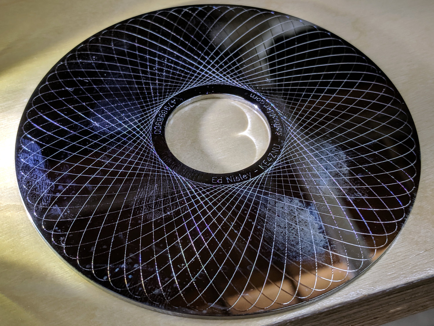
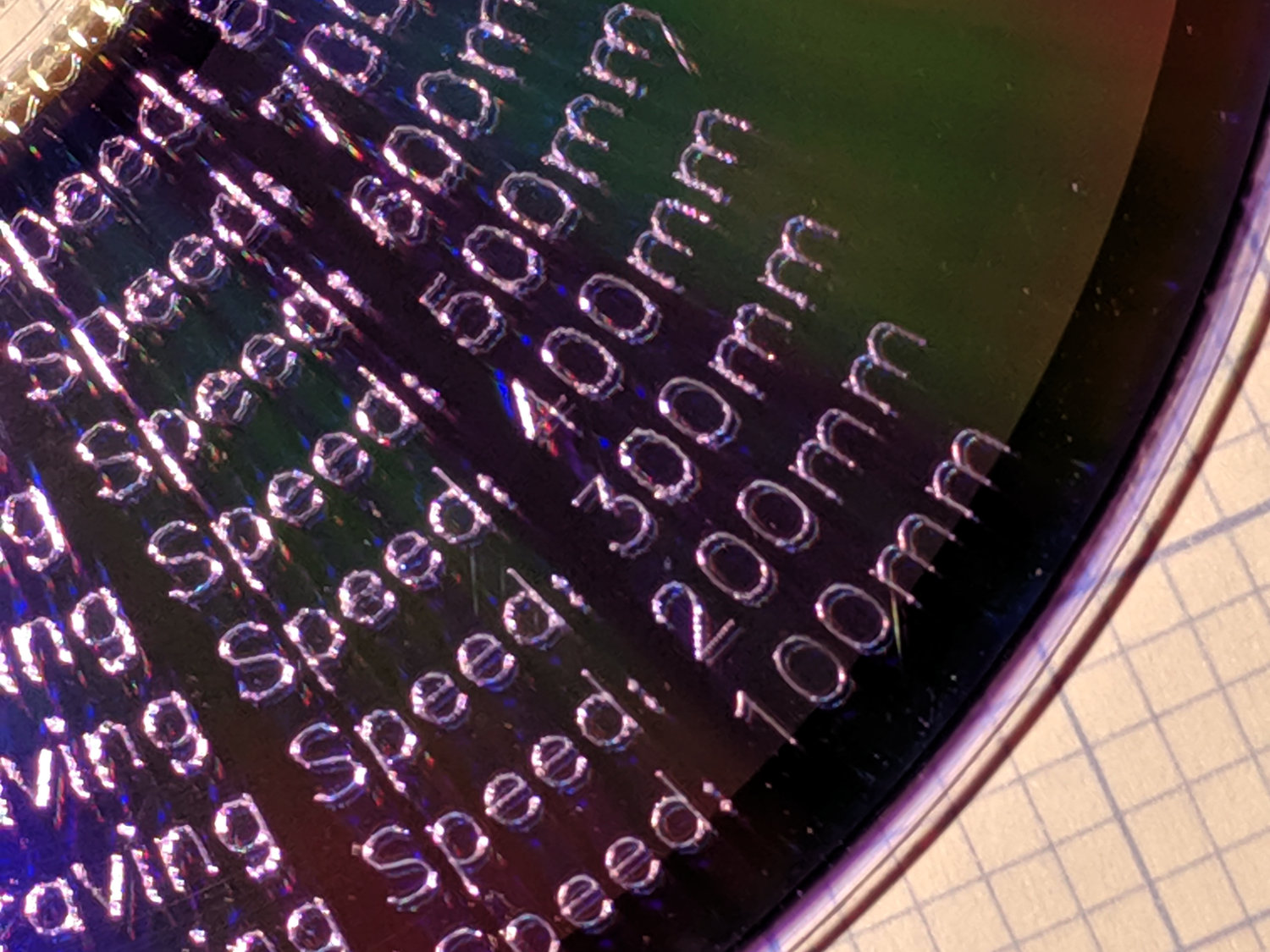
    Smooth curves, like Guillloché patterns, can run much faster, because they don’t have abrupt direction changes. This 3-½ inch hard drive platter has text engraved at 100 mm/min and the pattern at 600 mm/min, both at -3.0 mm for 300 g of downforce:

    MPCNC Engraving - Guilloche drive platter test
    MPCNC Engraving – Guilloche drive platter test

    A closer look at the text:

    MPCNC Engraving - hard drive platter - detail A
    MPCNC Engraving – hard drive platter – detail A
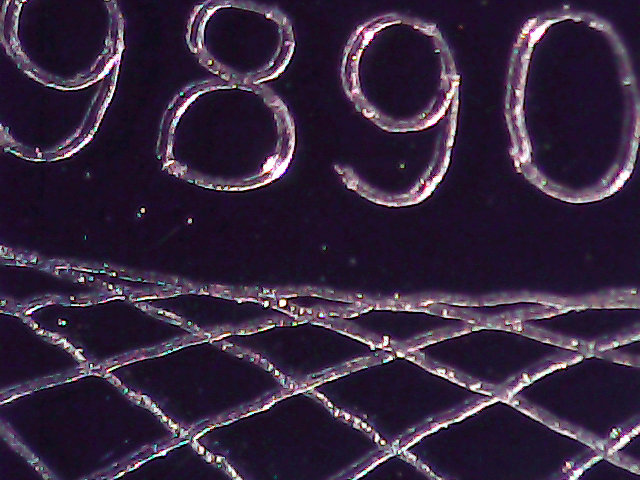
    And some digits:

    MPCNC Engraving - hard drive platter - detail B
    MPCNC Engraving – hard drive platter – detail B

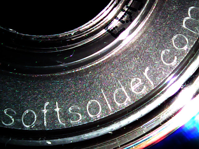
    When I want to brand an engraved CD, this will suffice:

    MPCNC Engraving - CD attribution text
    MPCNC Engraving – CD attribution text

    All in all, the MPCNC engraves much better than I expected!

  • Drag Knife Blade Ejector Handle

    The LM12UU drag knife holder buries the blade ejector pin deep inside the machinery:

    Drag Knife - LM12UU ground shaft - assembled
    Drag Knife – LM12UU ground shaft – assembled

    So a handle with a pin makes sense:

    LM12UU Drag Knife Ejector Pin Pusher
    LM12UU Drag Knife Ejector Pin Pusher

    It’s a variant Sherline tommy bar handle, so there’s not much to say about it.

    The dark butt end comes from the traces of the black filament I used for the previous part. Even after flushing half a meter of orange through the hot end, you’ll still see some contamination, even with the same type of plastic. Doesn’t make much difference here, though.

  • MPCNC Collet Pen Holder: LM12UU Edition

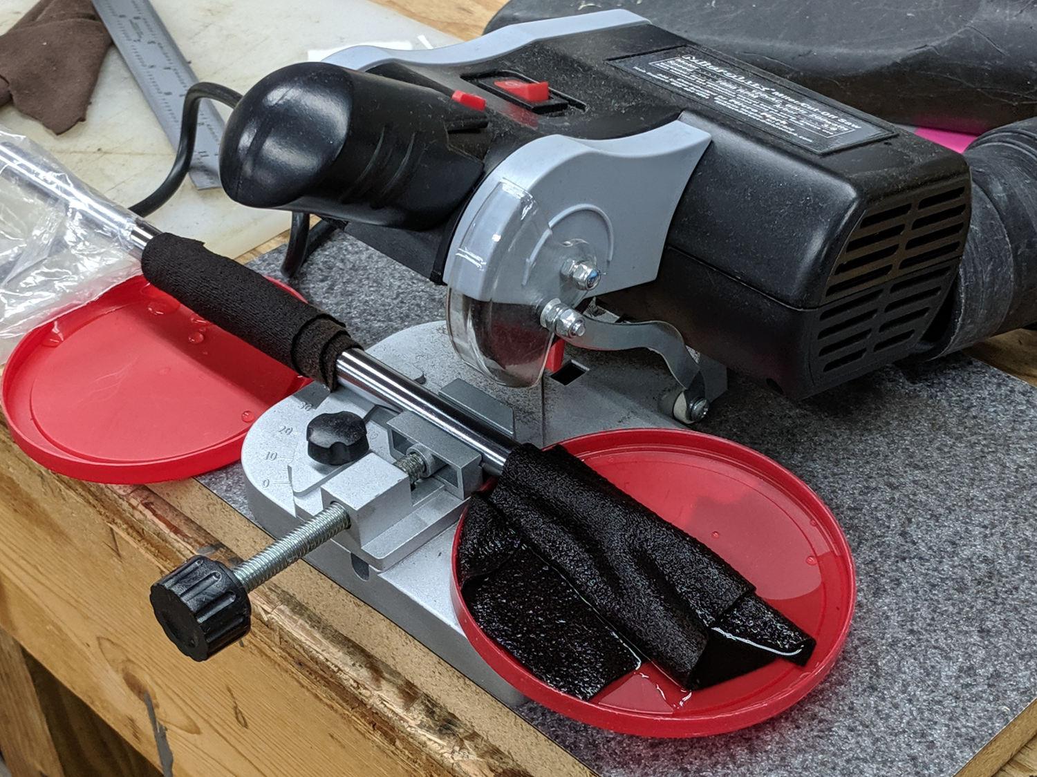
    Encouraged by the smooth running of the LM12UU drag knife mount, I chopped off another length of 12 mm shaft:

    LM12UU Collet Pen Holder - sawing shaft
    LM12UU Collet Pen Holder – sawing shaft

    The MicroMark Cut-off saw was barely up to the task; I must do something about its craptastic “vise”. In any event, the wet rags kept the shaft plenty cool and the ShopVac hose directly behind the motor sucked away all of the flying grit.

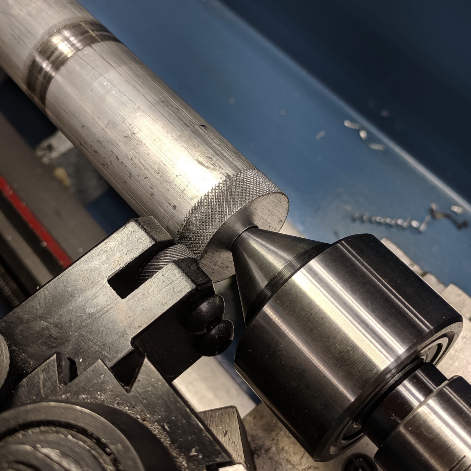
    The reason I used an abrasive wheel: the shaft is case-hardened and the outer millimeter or two is hard enough to repel a carbide cutter:

    LM12UU Collet Pen Holder - drilling shaft
    LM12UU Collet Pen Holder – drilling shaft

    Fortunately, the middle remains soft enough to drill a hole for the collet pen holder, which I turned down to a uniform 8 mm (-ish) diameter:

    LM12UU Collet Pen Holder - turning collet body
    LM12UU Collet Pen Holder – turning collet body

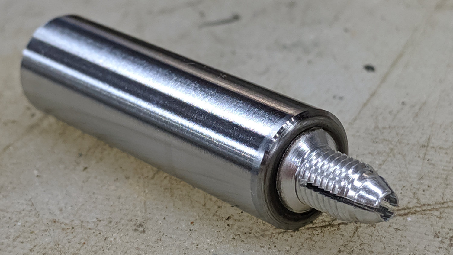
    Slather JB Kwik epoxy along the threads, insert into the shaft, wipe off the excess, and it almost looks like a Real Product:

    LM12UU Collet Pen Holder - finished body
    LM12UU Collet Pen Holder – finished body

    The far end of the shaft recesses the collet a few millimeters to retain the spring around the pen body, which will also require a knurled ring around the outside so you (well, I) can tighten the collet around the pen tip.

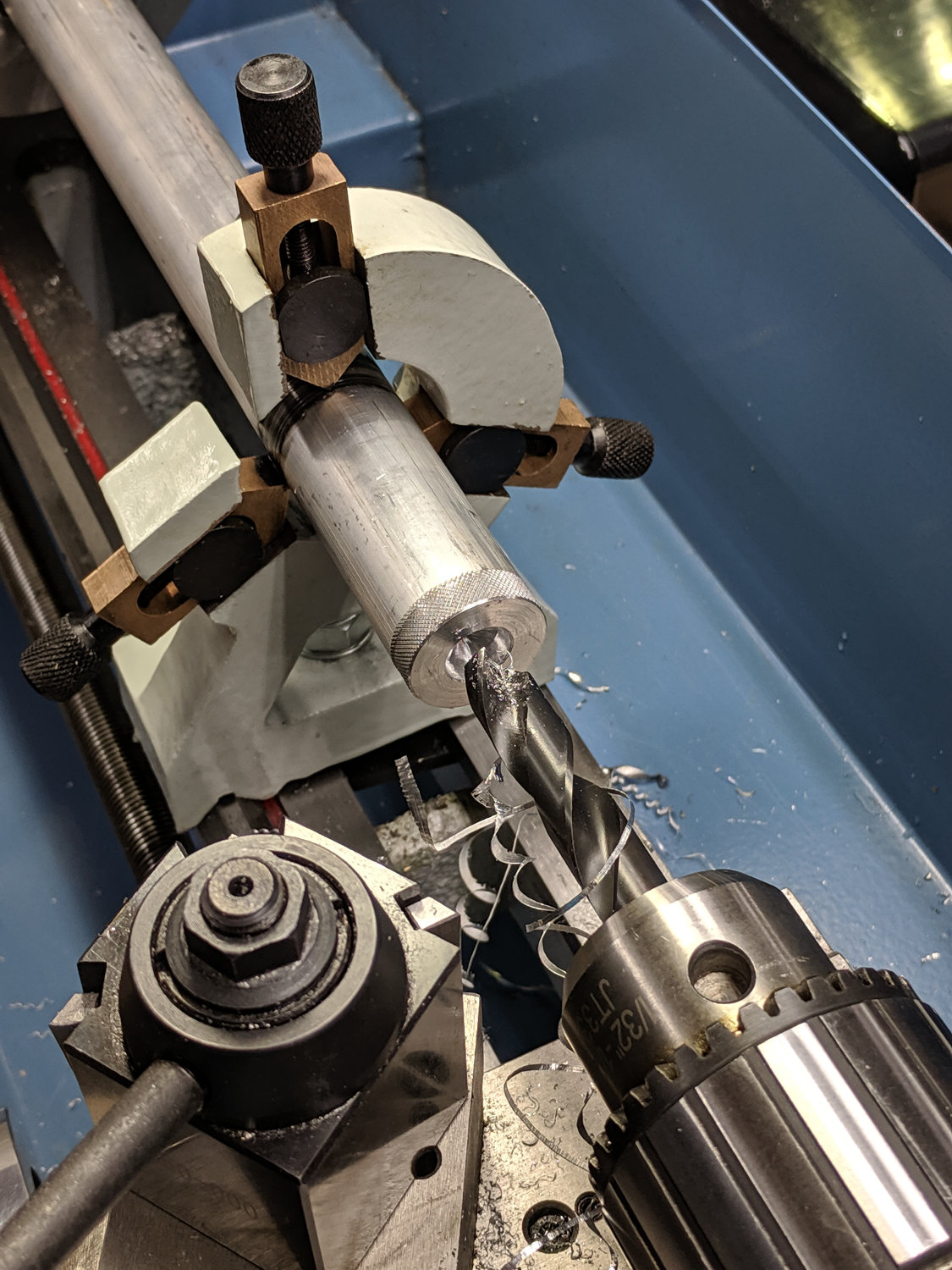
    Start the ring by center-drilling an absurdly long aluminum rod in the steady rest:

    M12UU Collet Pen Holder - center drilling
    M12UU Collet Pen Holder – center drilling

    Although it’s not obvious, I cleaned up the OD before applying the knurling tool:

    LM12UU Collet Pen Holder - knurling
    LM12UU Collet Pen Holder – knurling

    For some unknown reason, it seemed like a Good Idea to knurl without the steady rest, perhaps to avoid deepening the ring where the jaws slide, but Tiny Lathe™ definitely wasn’t up to the challenge. The knurling wheels aren’t quite concentric on their bores and their shafts have plenty of play, so I got to watch the big live center and tailstock wobbulate as the rod turned.

    With the steady rest back in place, drill out the rod to match the shaft’s 12 mm OD:

    LM12UU Collet Pen Holder - drilling shaft
    LM12UU Collet Pen Holder – drilling shaft

    All my “metric” drilling uses hard-inch drills approximating the metric dimensions, of course, because USA.

    Clean up the ring face, file a chamfer on the edge, and part it off:

    LM12UU Collet Pen Holder - parting ring
    LM12UU Collet Pen Holder – parting ring

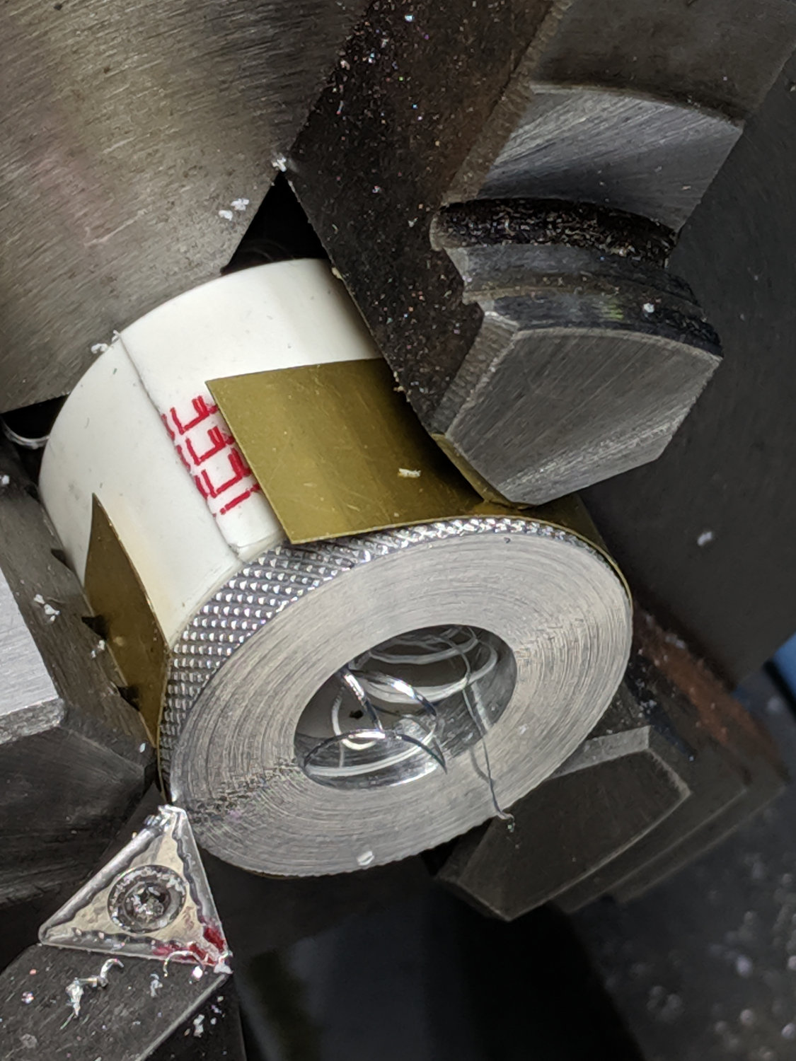
    Turn some PVC pipe to a suitable length, slit one side so it can collapse to match the ring OD, wrap shimstock to protect those lovely knurls, and face off all the ugly:

    LM12UU Collet Pen Holder - knurled ring facing
    LM12UU Collet Pen Holder – knurled ring facing

    Tweak the drag knife’s solid model for a different spring from the collection and up the hole OD in the plate to clear the largest pen cartridge in the current collection:

    Collet Holder - LM12UU - solid model
    Collet Holder – LM12UU – solid model

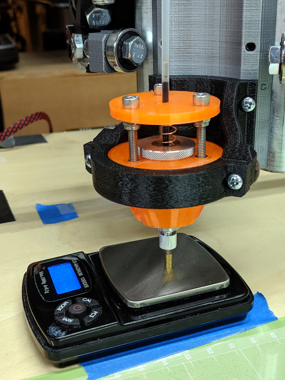
    Convince all the parts to fly in formation, then measure the spring rate:

    LM12UU Collet Pen Holder - spring rate test
    LM12UU Collet Pen Holder – spring rate test

    Which works out to be 128 g + 54 g/mm:

    LM12UU Collet Pen Holder - test plot - overview
    LM12UU Collet Pen Holder – test plot – overview

    I forgot the knurled ring must clear the screws and, ideally, the nyloc nuts. Which it does, after I carefully aligned each nut with a flat exactly tangent to the ring. Whew!

    A closer look at the business end:

    LM12UU Collet Pen Holder - test plot - detail
    LM12UU Collet Pen Holder – test plot – detail

    The shaft has 5 mm of travel, far more than enough for the MPCNC’s platform. Plotting at -1 mm applies 180 g of downforce; the test pattern shown above varies the depth from 0.0 mm in steps of -0.1 mm; anything beyond -0.2 mm gets plenty of ink.

    Now I have a pen holder, a diamond scribe, and a drag knife with (almost) exactly the same “tool offset” from the alignment camera, thereby eliminating an opportunity to screw up.

    The OpenSCAD source code as a GitHub Gist:

    // Collet pen cartridge holder using LM12UU linear bearing
    // Ed Nisley KE4ZNU – 2019-04-26
    // 2019-06 Adapted from LM12UU drag knife holder
    Layout = "Build"; // [Build, Show, Puck, Mount, Plate]
    /* [Extrusion] */
    ThreadThick = 0.25; // [0.20, 0.25]
    ThreadWidth = 0.40; // [0.40]
    /* [Hidden] */
    Protrusion = 0.1; // [0.01, 0.1]
    HoleWindage = 0.2;
    inch = 25.4;
    function IntegerMultiple(Size,Unit) = Unit * ceil(Size / Unit);
    ID = 0;
    OD = 1;
    LENGTH = 2;
    //- Adjust hole diameter to make the size come out right
    module PolyCyl(Dia,Height,ForceSides=0) { // based on nophead's polyholes
    Sides = (ForceSides != 0) ? ForceSides : (ceil(Dia) + 2);
    FixDia = Dia / cos(180/Sides);
    cylinder(r=(FixDia + HoleWindage)/2,h=Height,$fn=Sides);
    }
    //- Dimensions
    // Basic shape of DW660 snout fitting into the holder
    // Lip goes upward to lock into MPCNC mount
    Snout = [44.6,50.0,9.6]; // LENGTH = ID height
    Lip = 4.0; // height of lip at end of snout
    // Holder & suchlike
    Spring = [8.8,10.0,3*ThreadThick]; // compression spring loading knife blade
    PenShaft = 4.5; // hole to pass pen cartridge
    WallThick = 4.0; // minimum thickness / width
    Screw = [4.0,8.5,25.0]; // thread ID, washer OD, length
    Insert = [4.0,6.0,10.0]; // brass insert
    Bearing = [12.0,21.0,30.0]; // linear bearing body
    Plate = [PenShaft,Snout[OD] – WallThick,WallThick]; // spring reaction plate
    echo(str("Plate: ",Plate));
    SpringSeat = [0.56,7.2,2*ThreadThick]; // wire = ID, coil = OD, seat depth = length
    PuckOAL = max(Bearing[LENGTH],(Snout[LENGTH] + Lip)); // total height of DW660 fitting
    echo(str("PuckOAL: ",PuckOAL));
    Key = [Snout[ID],25.7,(Snout[LENGTH] + Lip)]; // rectangular key
    NumScrews = 3;
    //ScrewBCD = 2.0*(Bearing[OD]/2 + Insert[OD]/2 + WallThick);
    ScrewBCD = (Snout[ID] + Bearing[OD])/2;
    echo(str("Screw BCD: ",ScrewBCD));
    NumSides = 9*4; // cylinder facets (multiple of 3 for lathe trimming)
    module DW660Puck() {
    translate([0,0,PuckOAL])
    rotate([180,0,0]) {
    cylinder(d=Snout[OD],h=Lip/2,$fn=NumSides);
    translate([0,0,Lip/2])
    cylinder(d1=Snout[OD],d2=Snout[ID],h=Lip/2,$fn=NumSides);
    cylinder(d=Snout[ID],h=(Snout[LENGTH] + Lip),$fn=NumSides);
    translate([0,0,(Snout[LENGTH] + Lip) – Protrusion])
    cylinder(d1=Snout[ID],d2=2*WallThick + Bearing[OD],h=PuckOAL – (Snout[LENGTH] + Lip),$fn=NumSides);
    intersection() {
    translate([0,0,0*Lip + Key.z/2])
    cube(Key,center=true);
    cylinder(d=Snout[OD],h=Lip + Key.z,$fn=NumSides);
    }
    }
    }
    module MountBase() {
    difference() {
    DW660Puck();
    translate([0,0,-Protrusion]) // bearing
    PolyCyl(Bearing[OD],2*PuckOAL,NumSides);
    for (i=[0:NumScrews – 1]) // clamp screws
    rotate(i*360/NumScrews)
    translate([ScrewBCD/2,0,-Protrusion])
    rotate(180/8)
    PolyCyl(Insert[OD],2*PuckOAL,8);
    }
    }
    module SpringPlate() {
    difference() {
    cylinder(d=Plate[OD],h=Plate[LENGTH],$fn=NumSides);
    translate([0,0,-Protrusion]) // pen cartridge hole
    PolyCyl(PenShaft,2*Plate[LENGTH],NumSides);
    translate([0,0,Plate[LENGTH] – Spring[LENGTH]]) // spring retaining recess
    PolyCyl(Spring[OD],Spring[LENGTH] + Protrusion,NumSides);
    for (i=[0:NumScrews – 1]) // clamp screws
    rotate(i*360/NumScrews)
    translate([ScrewBCD/2,0,-Protrusion])
    rotate(180/8)
    PolyCyl(Screw[ID],2*PuckOAL,8);
    if (false)
    for (i=[0:NumScrews – 1]) // coil positioning recess
    rotate(i*360/NumScrews)
    translate([ScrewBCD/2,0,-Protrusion])
    rotate(180/8)
    PolyCyl(SpringSeat[OD],SpringSeat[LENGTH] + Protrusion,8);
    }
    }
    //—–
    // Build it
    if (Layout == "Puck")
    DW660Puck();
    if (Layout == "Plate")
    SpringPlate();
    if (Layout == "Mount")
    MountBase();
    if (Layout == "Show") {
    MountBase();
    translate([0,0,1.6*PuckOAL])
    rotate([180,0,0])
    SpringPlate();
    }
    if (Layout == "Build") {
    translate([0,Snout[OD]/2,PuckOAL])
    rotate([180,0,0])
    MountBase();
    translate([0,-Snout[OD]/2,0])
    SpringPlate();
    }
  • Wrapping GCMC Text Around Arcs

    GCMC includes a typeset function converting a more-or-less ASCII string into the coordinate points (a “vectorlist” containing a “path”) defining its character strokes and pen motions. The coordinates are relative to an origin at the lower-left corner of the line, with the font’s capital-X height set to 1.0, so you apply a scale function to make them whatever size you want and hand them to the engrave library routine, which squirts the corresponding G-Code into the output file.

    Such G-Code can annotate plots:

    Guilloche 213478839
    Guilloche 213478839

    Given that the plots appear on relentlessly circular CDs and hard drive platters, It Would Be Nice to wrap text around a circular arc, thusly:

    Diamond Scribe - LM3UU - arc text - first light
    Diamond Scribe – LM3UU – arc text – first light

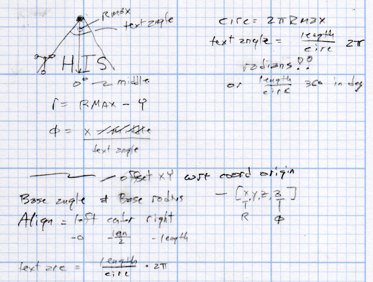
    The scaled coordinates cover a distance L along a straight line, so putting them on an arc will cover the same distance. The arc is part of a circle with radius R and a circumference 2πR, so … polar coordinates to the rescue!

    The total text length L corresponds to the total angle A along the arc:

    A = 360° L / 2πR

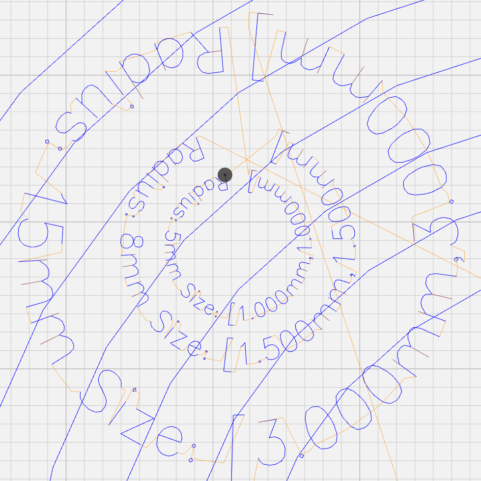
    It’s entirely possible to have a text line longer than the entire circumference of the circle, whereupon the right end overlaps the left. Smaller characters fit better on smaller circles:

    Arc Lettering - Small radius test - NCViewer
    Arc Lettering – Small radius test – NCViewer

    The X coordinate of each point in the path (always positive from the X origin) in the path gives its angle (positive counterclockwise) from 0°:

    a = 360° x / 2πR (say "eks")

    You can add a constant angle of either sign to slew the whole text arc around the center point.

    The letter baseline Y=0 sits at radius R, so the Y coordinate of each point (positive above and negative below the Y=0 baseline) gives its radius r:

    r = R - y

    That puts the bottom of the text outward, so it reads properly when you’re facing the center point.

    Homework: Tweak the signs so it reads properly when you’re standing inside the circle reading outward.

    Converting from polar back to XY:

    x = r × cos(a) (say "times")
    y = r × sin(a)

    You can add an XY offset to the result, thereby plunking the point wherever you want.

    This obviously works best for small characters relative to the arc radius, as the lines connecting the points remain resolutely straight. That’s probably what you wanted anyway, but letters like, say, “m” definitely manspread.

    Overall, it looks pretty good:

    Arc Lettering - test plot overview - NCViewer
    Arc Lettering – test plot overview – NCViewer

    A doodle helped lay out the geometry:

    Arc Lettering - geometry doodles
    Arc Lettering – geometry doodles

    The GCMC source code as a GitHub Gist:

    // Map text to circular arcs
    // Ed Nisley KE4ZNU – 2019-06
    //—–
    // Command line parameters
    // -D OuterDia=number
    if (!isdefined("OuterDia")) {
    OuterDia = 120mm – 2mm; // CD = 120, 3.5 inch drive = 95
    }
    OuterRad = OuterDia / 2.0;
    comment("Outer Diameter: ",OuterDia);
    comment(" Radius: ",OuterRad);
    //—–
    // Library routines
    include("tracepath.inc.gcmc");
    include("engrave.inc.gcmc");
    //—–
    // Bend text around an arc
    function ArcText(TextPath,Center,Radius,BaseAngle,Align) {
    PathLength = TextPath[-1].x – TextPath[1].x;
    Circumf = 2*pi()*Radius;
    TextAngle = to_deg(360 * PathLength / Circumf);
    AlignAngle = BaseAngle + (Align == "Left" ? 0 :
    Align == "Center" ? -TextAngle / 2 :
    Align == "Right" ? -TextAngle :
    0);
    ArcPath = {};
    foreach(TextPath; pt) {
    if (!isundef(pt.x) && !isundef(pt.y) && isundef(pt.z)) { // XY motion, no Z
    r = Radius – pt.y;
    a = 360deg * (pt.x / Circumf) + AlignAngle;
    ArcPath += {[r*cos(a) + Center.x, r*sin(a) + Center.y,-]};
    }
    elif (isundef(pt.x) && isundef(pt.y) && !isundef(pt.z)) { // no XY, Z up/down
    ArcPath += {pt};
    }
    else {
    error("Point is not pure XY or pure Z: " + to_string(pt));
    }
    }
    return ArcPath;
    }
    //—–
    // Set up for drawing
    TravelZ = 1.0mm; // no clamps above workpiece!
    PlotZ = -1.0mm; // tune for best results
    TextSpeed = 100mm; // minimal shaking
    DrawSpeed = 500mm; // smooth curve drawing
    TextFont = FONT_HSANS_1_RS;
    TextSize = [2.0mm,2.0mm];
    TextLeading = 5.0mm; // line spacing
    DiskCenter = [0mm,0mm]; // middle of the platter
    if (1) {
    comment("Circles begin");
    TextRadius = OuterRad;
    for (r = OuterRad; r >= 25mm; r -= TextLeading) {
    feedrate(DrawSpeed);
    goto([-,-,TravelZ]);
    goto([r,0,-]);
    move([-,-,PlotZ]);
    circle_cw([0,0]);
    goto([-,-,TravelZ]);
    tp = scale(typeset("Radius: " + to_string(r),TextFont),TextSize);
    tpa = ArcText(tp,DiskCenter,r,115deg,"Left");
    feedrate(TextSpeed);
    engrave(tpa,TravelZ,PlotZ);
    }
    }
    if (1) {
    comment("Depth variations begin");
    TextRadius = OuterRad;
    feedrate(TextSpeed);
    for (pz = 0.0mm; pz >= -0.6mm; pz -= 0.10mm) {
    comment(" depth: " + to_string(pz));
    ts = "Depth: " + to_string(pz) + " at " + to_string(TextSpeed) + "/s";
    tp = scale(typeset(ts,TextFont),TextSize);
    tpa = ArcText(tp,DiskCenter,TextRadius,-5deg,"Right");
    engrave(tpa,TravelZ,pz);
    TextRadius -= TextLeading;
    }
    }
    if (1) {
    comment("Feedrate variations begin");
    TextRadius = OuterRad;
    for (ps = 50mm; ps <= 350mm; ps += 50mm) {
    feedrate(ps);
    comment(" speed: " + to_string(ps) + "/s");
    ts = "Speed: " + to_string(ps) + "/s at " + to_string(PlotZ);
    tp = scale(typeset(ts,TextFont),TextSize);
    tpa = ArcText(tp,DiskCenter,TextRadius,5deg,"Left");
    engrave(tpa,TravelZ,PlotZ);
    TextRadius -= TextLeading;
    }
    }
    if (1) {
    comment("Off-center text arcs begin");
    feedrate(TextSpeed);
    tc = [-40mm/sqrt(2),-40mm/sqrt(2)]; // center point
    r = 8mm;
    s = [1.5mm,1.5mm];
    ts = "Radius: " + to_string(r) + " Size: " + to_string(s);
    tp = scale(typeset(ts,TextFont),s);
    tpa = ArcText(tp,tc,r,0deg,"Center");
    engrave(tpa,TravelZ,PlotZ);
    r = 5mm;
    s = [1.0mm,1.0mm];
    ts = "Radius: " + to_string(r) + " Size: " + to_string(s);
    tp = scale(typeset(ts,TextFont),s);
    tpa = ArcText(tp,tc,r,0deg,"Center");
    engrave(tpa,TravelZ,PlotZ);
    r = 15mm;
    s = [3.0mm,3.0mm];
    ts = "Radius: " + to_string(r) + " Size: " + to_string(s);
    tp = scale(typeset(ts,TextFont),s);
    tpa = ArcText(tp,tc,r,0deg,"Center");
    engrave(tpa,TravelZ,PlotZ);
    }
    if (1) {
    comment("Attribution begins");
    tp = scale(typeset("Ed Nisley – KE4ZNU – softsolder.com",TextFont),TextSize);
    tpa = ArcText(tp,DiskCenter,15mm,0deg,"Center");
    feedrate(TextSpeed);
    engrave(tpa,TravelZ,PlotZ);
    }
    goto([-,-,10mm]);
    goto([0mm,0mm,-]);
    comment("Done!");
    view raw ArcLetter.gcmc hosted with ❤ by GitHub
    #!/bin/bash
    # Arc Lettering Generator
    # Ed Nisley KE4ZNU – 2019-06
    Diameter='OuterDia=116mm'
    Flags='-P 3 –pedantic'
    # Set these to match your file layout
    LibPath='/opt/gcmc/library'
    Prolog='/mnt/bulkdata/Project Files/Mostly Printed CNC/Firmware/gcmc/prolog.gcmc'
    Epilog='/mnt/bulkdata/Project Files/Mostly Printed CNC/Firmware/gcmc/epilog.gcmc'
    Script='/mnt/bulkdata/Project Files/Mostly Printed CNC/Patterns/Arc Lettering/ArcLetter.gcmc'
    ts=$(date +%Y%m%d-%H%M%S)
    fn='ArcLetter_'${ts}'.ngc'
    echo Output: $fn
    rm -f $fn
    echo "(File: "$fn")" > $fn
    gcmc -D $Diameter $Flags \
    –include "$LibPath" –prologue "$Prolog" –epilogue "$Epilog" \
    "$Script" >> $fn
    view raw ArcLetter.sh hosted with ❤ by GitHub
  • MPCNC Drag Knife: Ground Shaft in LM12UU Bearing

    The 12 mm drag knife holder on the left slides nicely in an LM12UU bearing:

    Drag Knife holders - detail
    Drag Knife holders – detail

    However, its aluminum body isn’t really intended as a bearing surface and it extends only halfway through the LM12UU, so I finally got around to modifying the 11.5 mm body on the right to fit into a section of 12 mm ground shaft:

    Drag Knife - turning 11.5 mm body to 10 mm
    Drag Knife – turning 11.5 mm body to 10 mm

    The general idea is to turn the body down to 10 mm OD; the picture shows the first pass over the nose after turning the far end down and removing the flange in the process. Exact concentricity of both ends isn’t important (it gets epoxied into a 10 mm hole through the 12 mm ground shaft), but it came out rather pretty:

    Drag Knife - 11.5 mm body - turned to 10 mm
    Drag Knife – 11.5 mm body – turned to 10 mm

    The ground shaft started as a pen holder:

    DW660 Pen Holder - ground shaft
    DW660 Pen Holder – ground shaft

    I knocked off the ring and bored the interior to fit the 10 mm knife body. The large end of the existing bore came from a 25/64 inch = 9.92 mm drill, so it was just shy of 10.0 mm, and I drilled the small end upward from 0.33 inch = 8.4 mm.

    The smallest trio of a new set of cheap carbide boring bars allegedly went into a 5/16 inch = 7.9 mm bore, but I had to file the bar body down and diamond-file more end relief into the carbide for clearance inside the drilled hole:

    Modified boring bar vs original
    Modified boring bar vs original

    I blued the bit, kissed it against the drilled bore, filed off whatever wasn’t blued, and iterated until the carbide edge started cutting. Sissy cuts all the way, with no pix to show for all the flailing around.

    Epoxying the turned-down drag knife body into the shaft: anticlimactic.

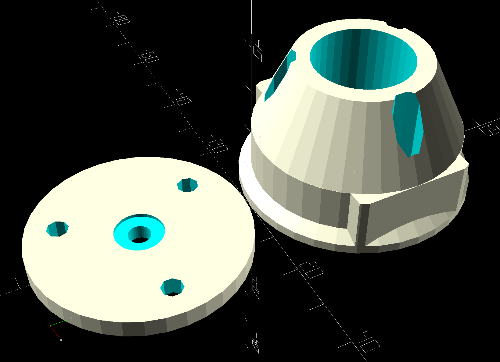
    The solid model features a stylin’ tapered snout:

    Drag Knife LM12UU holder - tapered end
    Drag Knife LM12UU holder – tapered end

    Which gets an LM12UU bearing rammed into place:

    Drag Knife - LM12UU holder - inserting bearing
    Drag Knife – LM12UU holder – inserting bearing

    The steel block leaves the bearing flush with the plastic surface, rather than having it continue onward and indent itself into the wood; I can learn from my mistakes.

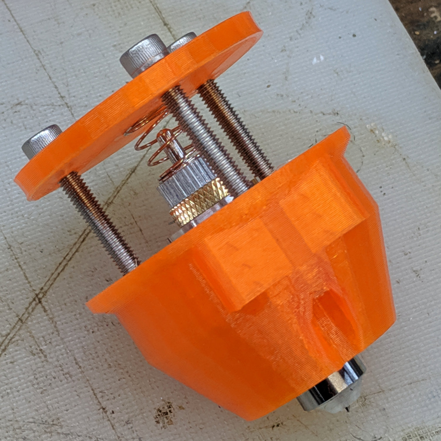
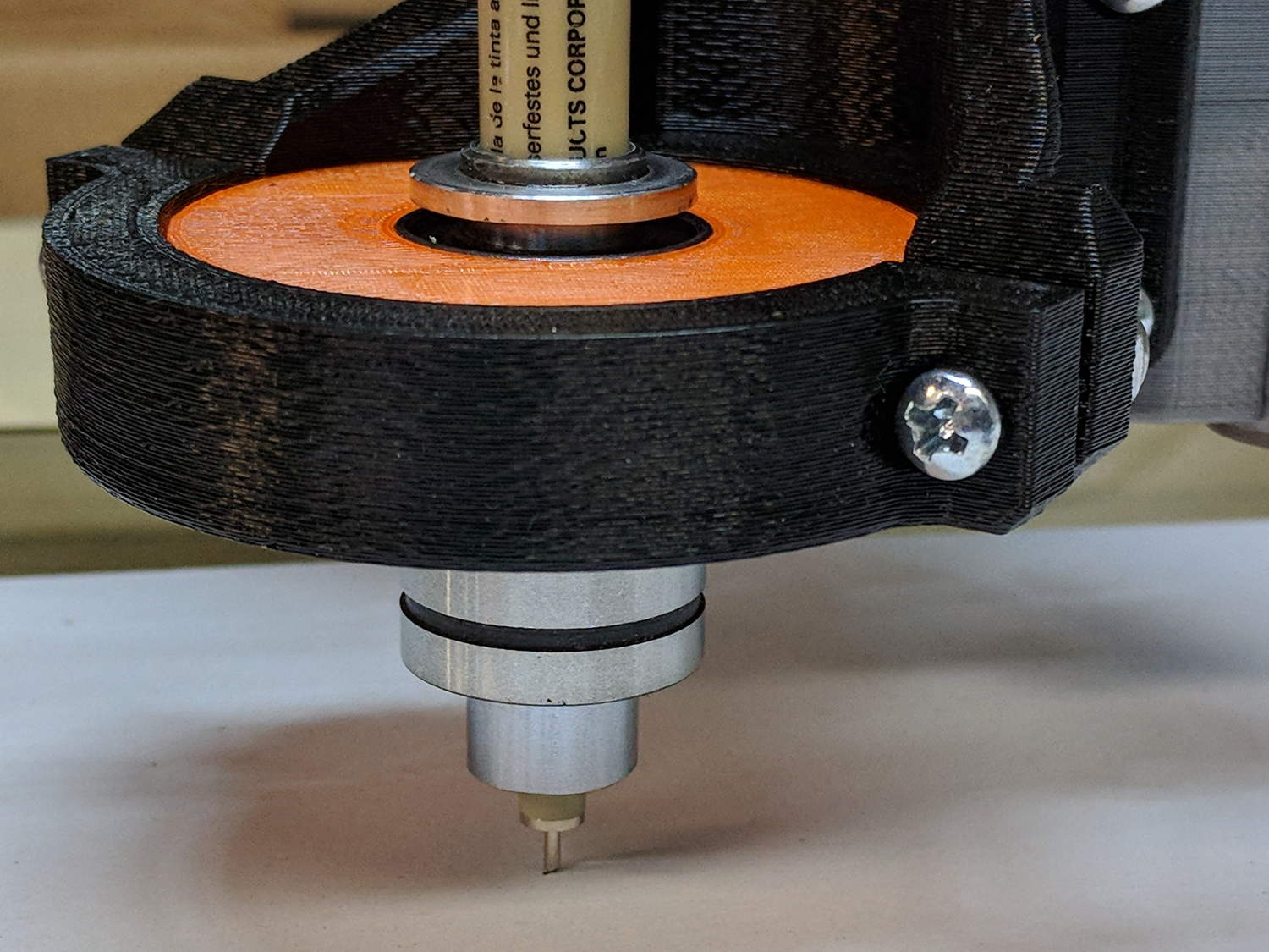
    The new idea: a single spring pressing the knife holder downward, reacting against a fixed plastic plate:

    Drag Knife - LM12UU ground shaft - assembled
    Drag Knife – LM12UU ground shaft – assembled

    Unlike the previous design, the upper plate doesn’t move, so there’s no problem caused by sliding along the screw threads. I should run nylock nuts up against the plate to keep it in place, stiffen the structure, and provide some friction to keep the screws from loosening.

    The top of the knife holder now has a boss anchoring the spring:

    Drag Knife - turning spring recess
    Drag Knife – turning spring recess

    As you’d expect, the ground shaft slides wonderfully in the bearing, because that’s what it’s designed to do, and the knife has essentially zero stiction and friction at any point along the bearing, which is exactly what I wanted.

    The spring, from the same assortment as all the others, has a 48 g/mm rate.

    The OpenSCAD source code as a GitHub Gist:

    // Drag Knife Holder using LM12UU linear bearing
    // Ed Nisley KE4ZNU – 2019-04-26
    // 2019-06-01 Taper the nose
    Layout = "Build"; // [Build, Show, Puck, Mount, Plate]
    /* [Extrusion] */
    ThreadThick = 0.25; // [0.20, 0.25]
    ThreadWidth = 0.40; // [0.40]
    /* [Hidden] */
    Protrusion = 0.1; // [0.01, 0.1]
    HoleWindage = 0.2;
    inch = 25.4;
    function IntegerMultiple(Size,Unit) = Unit * ceil(Size / Unit);
    ID = 0;
    OD = 1;
    LENGTH = 2;
    //- Adjust hole diameter to make the size come out right
    module PolyCyl(Dia,Height,ForceSides=0) { // based on nophead's polyholes
    Sides = (ForceSides != 0) ? ForceSides : (ceil(Dia) + 2);
    FixDia = Dia / cos(180/Sides);
    cylinder(r=(FixDia + HoleWindage)/2,h=Height,$fn=Sides);
    }
    //- Dimensions
    // Basic shape of DW660 snout fitting into the holder
    // Lip goes upward to lock into MPCNC mount
    Snout = [44.6,50.0,9.6]; // LENGTH = ID height
    Lip = 4.0; // height of lip at end of snout
    // Knife holder & suchlike
    KnifeBody = [12.0,18.0,2.0]; // body OD, flange OD, flange thickness
    Spring = [9.5,10.0,3*ThreadThick]; // compression spring loading knife blade
    PinAccess = 4.0; // hole to reach knife ejection pin
    WallThick = 4.0; // minimum thickness / width
    Screw = [4.0,8.5,25.0]; // thread ID, washer OD, length
    Insert = [4.0,6.0,10.0]; // brass insert
    Bearing = [12.0,21.0,30.0]; // linear bearing body
    Plate = [PinAccess,Snout[OD] – WallThick,WallThick]; // spring reaction plate
    echo(str("Plate: ",Plate));
    SpringSeat = [0.56,7.2,2*ThreadThick]; // wire = ID, coil = OD, seat depth = length
    PuckOAL = max(Bearing[LENGTH],(Snout[LENGTH] + Lip)); // total height of DW660 fitting
    echo(str("PuckOAL: ",PuckOAL));
    Key = [Snout[ID],25.7,(Snout[LENGTH] + Lip)]; // rectangular key
    NumScrews = 3;
    //ScrewBCD = 2.0*(Bearing[OD]/2 + Insert[OD]/2 + WallThick);
    ScrewBCD = (Snout[ID] + Bearing[OD])/2;
    NumSides = 9*4; // cylinder facets (multiple of 3 for lathe trimming)
    module DW660Puck() {
    translate([0,0,PuckOAL])
    rotate([180,0,0]) {
    cylinder(d=Snout[OD],h=Lip/2,$fn=NumSides);
    translate([0,0,Lip/2])
    cylinder(d1=Snout[OD],d2=Snout[ID],h=Lip/2,$fn=NumSides);
    cylinder(d=Snout[ID],h=(Snout[LENGTH] + Lip),$fn=NumSides);
    translate([0,0,(Snout[LENGTH] + Lip) – Protrusion])
    cylinder(d1=Snout[ID],d2=2*WallThick + Bearing[OD],h=PuckOAL – (Snout[LENGTH] + Lip),$fn=NumSides);
    intersection() {
    translate([0,0,0*Lip + Key.z/2])
    cube(Key,center=true);
    cylinder(d=Snout[OD],h=Lip + Key.z,$fn=NumSides);
    }
    }
    }
    module MountBase() {
    difference() {
    DW660Puck();
    translate([0,0,-Protrusion]) // bearing
    PolyCyl(Bearing[OD],2*PuckOAL,NumSides);
    for (i=[0:NumScrews – 1]) // clamp screws
    rotate(i*360/NumScrews)
    translate([ScrewBCD/2,0,-Protrusion])
    rotate(180/8)
    PolyCyl(Insert[OD],2*PuckOAL,8);
    }
    }
    module SpringPlate() {
    difference() {
    cylinder(d=Plate[OD],h=Plate[LENGTH],$fn=NumSides);
    translate([0,0,-Protrusion]) // ejection pin hole
    PolyCyl(PinAccess,2*Plate[LENGTH],NumSides);
    translate([0,0,Plate[LENGTH] – Spring[LENGTH]]) // spring retaining recess
    PolyCyl(Spring[OD],Spring[LENGTH] + Protrusion,NumSides);
    for (i=[0:NumScrews – 1]) // clamp screws
    rotate(i*360/NumScrews)
    translate([ScrewBCD/2,0,-Protrusion])
    rotate(180/8)
    PolyCyl(Screw[ID],2*PuckOAL,8);
    if (false)
    for (i=[0:NumScrews – 1]) // coil positioning recess
    rotate(i*360/NumScrews)
    translate([ScrewBCD/2,0,-Protrusion])
    rotate(180/8)
    PolyCyl(SpringSeat[OD],SpringSeat[LENGTH] + Protrusion,8);
    }
    }
    //—–
    // Build it
    if (Layout == "Puck")
    DW660Puck();
    if (Layout == "Plate")
    SpringPlate();
    if (Layout == "Mount")
    MountBase();
    if (Layout == "Show") {
    MountBase();
    translate([0,0,1.6*PuckOAL])
    rotate([180,0,0])
    SpringPlate();
    }
    if (Layout == "Build") {
    translate([0,Snout[OD]/2,PuckOAL])
    rotate([180,0,0])
    MountBase();
    translate([0,-Snout[OD]/2,0])
    SpringPlate();
    }
  • MPCNC Diamond Engraver: LM3UU Bearings, First Pass

    Gripping a diamond engraver in a collet chuck worked well enough, but the MPCNC’s pen holder lacks sufficient downforce and lateral stiffness. The bit has a chrome-ish plated 3 mm shank, so I tinkered up a mount for a pair of LM3UU linear bearings from the LM12UU drag knife holder:

    Diamond Scribe - LM3UU - Rev 1 - point view
    Diamond Scribe – LM3UU – Rev 1 – point view

    The shank isn’t exactly a precision part, but a few licks with a diamond file knocked off enough of the high spots so it slides reasonably well through the bearings. The bearing alignment is more critical than a simple 3D printed plastic part can provide, so a real version may need bearings in a metal shaft press-fit into the plastic; brute-forcing the bearings into alignment sufficed for now.

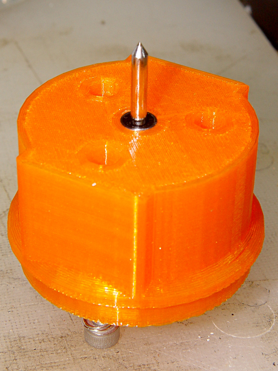
    The butt end of the shank press-fits into a disk held down with three springs, similar to the LM12UU mount:

    Diamond Scribe - LM3UU - Rev 1 - top view
    Diamond Scribe – LM3UU – Rev 1 – top view

    It draws Guilloché patterns just fine:

    Diamond Scribe - LM3UU - Rev 1 - first light
    Diamond Scribe – LM3UU – Rev 1 – first light

    I don’t like how the spring-around-screw motion works, even if it’s OK for small excursions.

  • MPCNC Drag Knife: LM12UU Linear Bearing

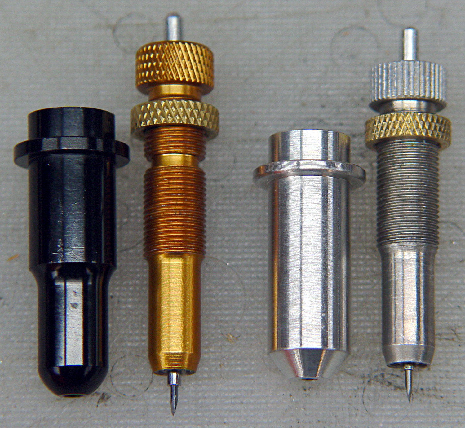
    The anodized body of the drag knife on the left measures exactly 12.0 mm OD:

    Drag Knife holders - detail
    Drag Knife holders – detail

    Which happy fact suggested I might be able to use a standard LM12UU linear bearing, despite the obvious stupidity of running an aluminum “shaft” in a steel-ball bearing race:

    Drag Knife - LM12UU holder - solid model
    Drag Knife – LM12UU holder – solid model

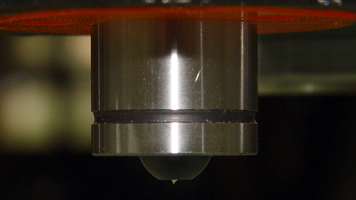
    The 12 mm section extends about halfway through the bearing, with barely 3 mm extending out the far end:

    Drag Knife - LM12UU - knife blade detail
    Drag Knife – LM12UU – knife blade detail

    Because the knife body isn’t touching the bearing for the lower half of its length, it’ll probably deflect too much in the XY plane, but it’s simple enough to try out.

    As before, the knife body’s flange is a snug fit in the hole bored in the upper disk:

    Drag Knife - spring plate test fit
    Drag Knife – spring plate test fit

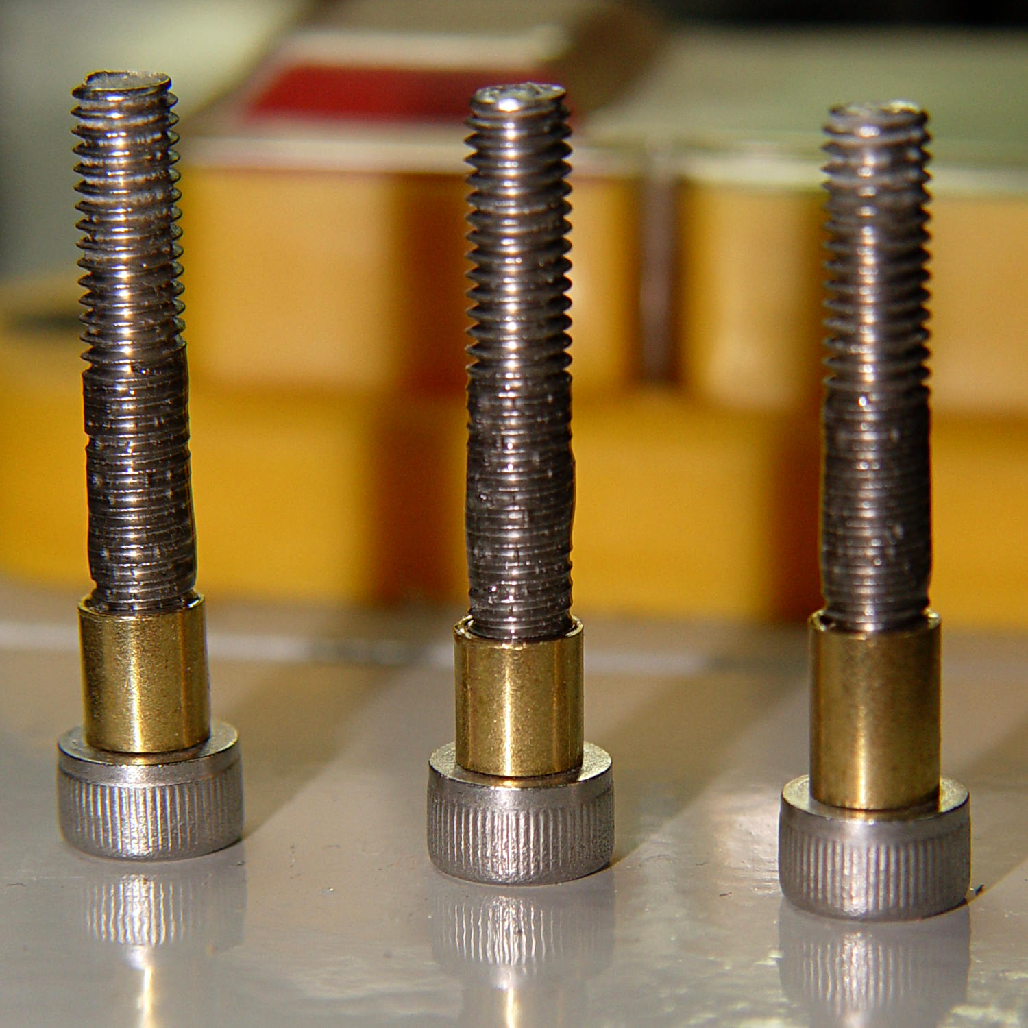
    This time, I tried faking stripper bolts by filling the threads of ordinary socket head cap screws with epoxy:

    Ersatz stripper bolts - epoxy fill
    Ersatz stripper bolts – epoxy fill

    Turning the filled section to match the thread OD showed this just wasn’t going to work at all, so I turned the gunked section of the threads down to about 3.5 mm and continued the mission:

    Drag Knife - LM12UU holder - assembled
    Drag Knife – LM12UU holder – assembled

    Next time, I’ll try mounting the disk on telescoping brass tubing nested around the screws. The motivation for the epoxy nonsense came from the discovery that real stainless steel stripper bolts run five bucks each, which means I’m just not stocking up on the things.

    It slide surprisingly well on the cut-down screws, though:

    Drag Knife - applique templates
    Drag Knife – applique templates

    Those appliqué templates came from patterns for a block in one of Mary’s current quilting projects, so perhaps I can be of some use whenever she next needs intricate cutouts.

    The OpenSCAD source code as a GitHub Gist:

    // Drag Knife Holder using LM12UU linear bearing
    // Ed Nisley KE4ZNU – 2019-04-26
    Layout = "Show"; // [Build, Show, Puck, Mount, Plate]
    /* [Extrusion] */
    ThreadThick = 0.25; // [0.20, 0.25]
    ThreadWidth = 0.40; // [0.40]
    /* [Hidden] */
    Protrusion = 0.1; // [0.01, 0.1]
    HoleWindage = 0.2;
    inch = 25.4;
    function IntegerMultiple(Size,Unit) = Unit * ceil(Size / Unit);
    ID = 0;
    OD = 1;
    LENGTH = 2;
    //- Adjust hole diameter to make the size come out right
    module PolyCyl(Dia,Height,ForceSides=0) { // based on nophead's polyholes
    Sides = (ForceSides != 0) ? ForceSides : (ceil(Dia) + 2);
    FixDia = Dia / cos(180/Sides);
    cylinder(r=(FixDia + HoleWindage)/2,h=Height,$fn=Sides);
    }
    //- Dimensions
    // Basic shape of DW660 snout fitting into the holder
    // Lip goes upward to lock into MPCNC mount
    Snout = [44.6,50.0,9.6]; // LENGTH = ID height
    Lip = 4.0; // height of lip at end of snout
    // Knife holder & suchlike
    KnifeBody = [12.0,15.9,2.0]; // flange epoxied to top of diamond shaft, with epoxy fillet
    WallThick = 4.0; // minimum thickness / width
    Screw = [4.0,8.5,8.0]; // holding it all together, OD = washer
    Insert = [4.0,6.0,10.0]; // brass insert
    Bearing = [12.0,21.0,30.0]; // linear bearing body
    Plate = [KnifeBody[ID],Snout[OD] – WallThick,KnifeBody[LENGTH] + WallThick]; // spring reaction plate
    PlateGuide = [4.0,4.8,Plate[LENGTH]]; // … guide tubes
    PuckOAL = max(Bearing[LENGTH],(Snout[LENGTH] + Lip)); // total height of DW660 fitting
    echo(str("PuckOAL: ",PuckOAL));
    Key = [Snout[ID],25.7,(Snout[LENGTH] + Lip)]; // rectangular key
    NumScrews = 3;
    ScrewBCD = 2.0*(Bearing[OD]/2 + Insert[OD]/2 + WallThick);
    NumSides = 9*4; // cylinder facets (multiple of 3 for lathe trimming)
    module DW660Puck() {
    translate([0,0,PuckOAL])
    rotate([180,0,0]) {
    cylinder(d=Snout[OD],h=Lip/2,$fn=NumSides);
    translate([0,0,Lip/2])
    cylinder(d1=Snout[OD],d2=Snout[ID],h=Lip/2,$fn=NumSides);
    cylinder(d=Snout[ID],h=PuckOAL,$fn=NumSides);
    intersection() {
    translate([0,0,0*Lip + Key.z/2])
    cube(Key,center=true);
    cylinder(d=Snout[OD],h=Lip + Key.z,$fn=NumSides);
    }
    }
    }
    module MountBase() {
    difference() {
    DW660Puck();
    translate([0,0,-Protrusion]) // bearing
    PolyCyl(Bearing[OD],2*PuckOAL,NumSides);
    for (i=[0:NumScrews – 1]) // clamp screws
    rotate(i*360/NumScrews)
    translate([ScrewBCD/2,0,-Protrusion])
    rotate(180/8)
    PolyCyl(Insert[OD],2*PuckOAL,8);
    }
    }
    module SpringPlate() {
    difference() {
    cylinder(d=Plate[OD],h=Plate[LENGTH],$fn=NumSides);
    translate([0,0,-Protrusion]) // knife holder body
    PolyCyl(KnifeBody[ID],2*PuckOAL,NumSides);
    translate([0,0,Plate[LENGTH] – KnifeBody[LENGTH]]) // flange, snug fit
    PolyCyl(KnifeBody[OD],KnifeBody[LENGTH] + Protrusion,NumSides);
    for (i=[0:NumScrews – 1]) // clamp screws
    rotate(i*360/NumScrews)
    translate([ScrewBCD/2,0,-Protrusion])
    rotate(180/8)
    PolyCyl(PlateGuide[OD],2*PuckOAL,8);
    }
    }
    //—–
    // Build it
    if (Layout == "Puck")
    DW660Puck();
    if (Layout == "Plate")
    SpringPlate();
    if (Layout == "Mount")
    MountBase();
    if (Layout == "Show") {
    MountBase();
    translate([0,0,1.6*PuckOAL])
    rotate([180,0,0])
    SpringPlate();
    }
    if (Layout == "Build") {
    translate([0,Snout[OD]/2,PuckOAL])
    rotate([180,0,0])
    MountBase();
    translate([0,-Snout[OD]/2,0])
    SpringPlate();
    }