Ed Nisley's Blog: Shop notes, electronics, firmware, machinery, 3D printing, laser cuttery, and curiosities. Contents: 100% human thinking, 0% AI slop.
One of the Tekronix AM503 current probe amplifiers arrived without the panel bushing for the Balance trim pot. Back in the day, you could presumably order part number 350-0301-02 and have it delivered (most likely) by your local Tek representative:
Balance pot panel bushing – Tek part listing
Those days are over.
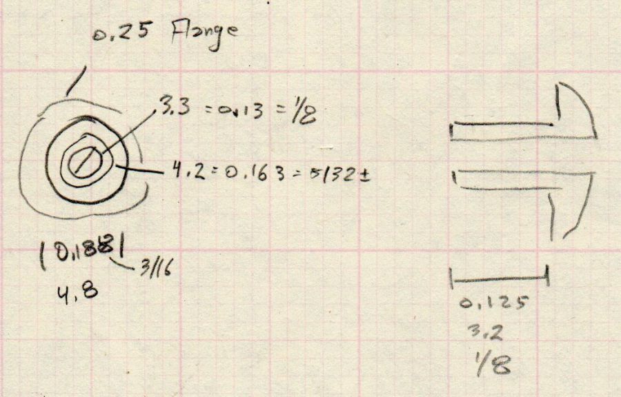
A few minutes produced a doodle with pretty-close measurements:
Balance pot panel bushing – dimension doodle
The as-built bushing turned out just a smidge too long, so make yours a scant eighth of an inch. Maybe the Tek dimension is the overall length?
An SLA resin printer might crank out such a thing, but it’s well below the looks-good / fits-well resolution limit of an ordinary fused-filament printer.
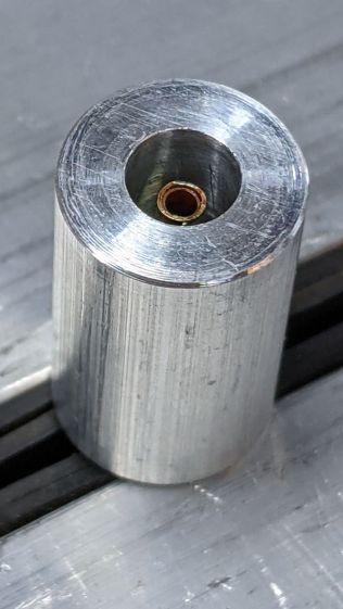
Applying the mini-lathe to a 1/4 inch white acrylic rod produced a reasonable facsimile:
Tek AM503 Balance pot bushing – front
The side view:
Tek AM503 Balance pot bushing – side
Acrylic is definitely the wrong material for the job, but it came readily to hand while pondering the Shelf o’ Rods. Acetal would be better, as you could easily trim off the aforementioned excess length with a knife.
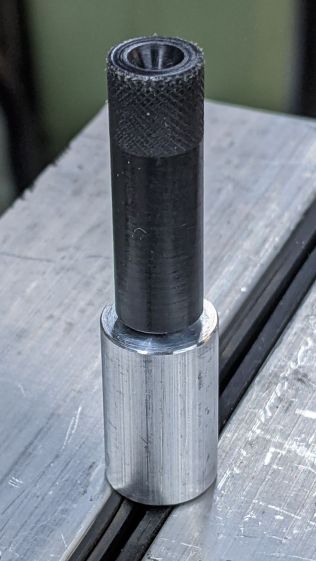
All’s well that ends well:
Tek AM503 Balance pot bushing – installed
A dab of white acrylic adhesive around the raw opening holds the bushing in place and it looks good enough to me.
The motivation for this boils down to having the bushing center the pot twiddler required to set the balance, which I must do every time I fire up the amps, even after waiting for the half-hour required to stabilize them at their operating temperature.
A lithium battery management system can (and should!) disable the battery output to prevent damage from overcurrent or undervoltage, after which it must be reset. The inadvertent charge port short may have damaged the BMS PCB, but did not shut down the battery’s motor output, which means the BMS will not should not require resetting. However, because all this will happen remotely, it pays to be prepared.
For this battery, the positive terminal is on the right, as shown by the molded legend and verified by measurement.
A doodle with various dimensions, most of which are pretty close:
Bafang battery – connector dimension doodle
Further doodling produced a BMS reset adapter keyed to fit the battery connector in only one way:
Bafang battery – adapter doodle
Which turned into the rectangular lump at the top of the tool kit, along with the various shell drills and suchlike discussed earlier:
Bafang battery tools
Looking into the solid model from the battery connector shows the notches and projections that prevent it from making incorrect contact:
Battery Reset Adapter – show front
The pin dimensions on the right, along with a mysterious doodle that must have meant something at the time :
Bafang battery – adapter pin doodle
The pins emerged from 3/16 inch brass rod, with pockets for the soldered wires:
Bafang battery – reset tool – pins
The wires go into a coaxial breakout connector that’s hot-melt glued into the recess. The coaxial connectors are rated for 12 V and intended for CCTV cameras, LED strings, and suchlike, but I think they’re good for momentary use at 48 V with minimal current.
I printed the block with the battery connector end on top for the best dimensional accuracy and the other end of the pin holes held in place by a single layer of filament bridging the rectangular opening:
Bafang battery – reset tool – hole support layer
I made a hollow punch to cut the bridge filaments:
Bafang battery – reset tool – pin hole punch
The holes extend along the rectangular cutout for the coaxial connector, so pressing the punch against the notch lines it up neatly with the hole:
Bafang battery – reset tool – hole punching
Whereupon a sharp rap with a hammer clears the hole:
Bafang battery – reset tool – hole cleared
A dollop of urethane adhesive followed the pins into their holes to lock them in place. I plugged the block and pins into the battery to align the pins as the adhesive cured, with the wire ends carefully taped apart.
After curing: unplug the adapter, screw wires into coaxial connector, slobber hot melt glue into the recess, squish into place, align, dribble more glue into all the gaps and over the screw terminals, then declare victory.
It may never be needed, but that’s fine with me.
[Update: A few more doodles with better dimensions and fewer malfeatures appeared from the back of the bench.]
This file contains hidden or bidirectional Unicode text that may be interpreted or compiled differently than what appears below. To review, open the file in an editor that reveals hidden Unicode characters.
Learn more about bidirectional Unicode characters
Rather than poke things into the undamagedcharge port of our battery, I built a quick-and-dirty mechanical duplicate:
Bafang battery – charge port simulator
The “center pin” is a snippet of what’s almost certainly 5/64 inch brass tube measuring Close Enough™ to 2.1 mm, with a few millimeters of 3/32 inch tube soldered on the end to simulate the nugget.
The aluminum rod has a 5.5 mm hole matching the coaxial jack’s diameter and depth, with a smaller through hole for the “pin” and a dab of Loctite bushing adhesive.
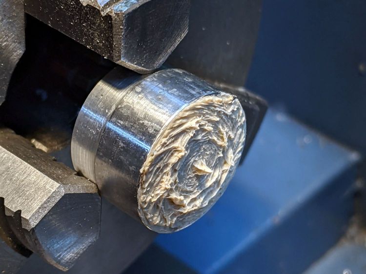
Then I turned the end of a 3/8 inch acetal rod down to a 5.5 mm bushing that completely fills the jack:
Bafang battery – guide bushing – dummy jack
It has a 3 mm hole down the middle to aim homebrew shell drills directly at the pin, while preventing a short to the side contact.
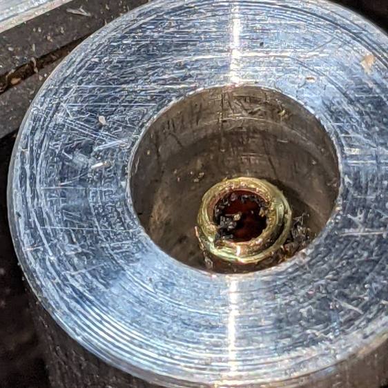
The first test looked encouraging:
Bafang battery – shell drill – test results
The nugget in the damaged jack is definitely larger than my soldered brass tube, but this was in the nature of exploratory tinkering while mulling the problem.
Because the tubes get epoxied into the adapters, there’s no particular need for a smooth surface finish and, in fact, some surface roughness makes for a good epoxy bond. The interior of a 3D printed adapter is nothing if not rough; the epoxy in between will be perfectly happy.
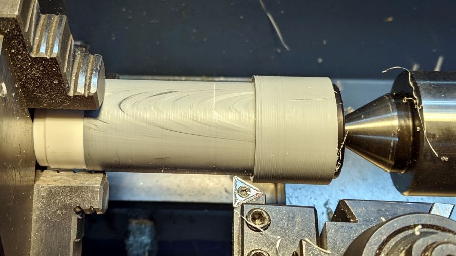
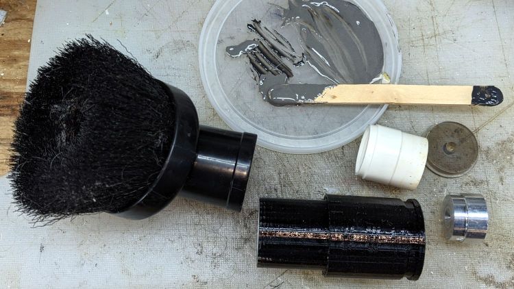
Turning the tubes started by just grabbing the conduit in the chuck and peeling the end that stuck out down to the finished diameter, because the conduit was thick-walled enough to let that work.
The remaining wall was so thin that the chuck would crunch it into a three-lobed shape, so the white ring in the chuck is a scrap of PVC pipe turned to fit the tube ID and provide enough reinforcement to keep the tube round.
The conduit ID isn’t a controlled dimension and was, in point of fact, not particularly round. It was, however, smooth, which counts for more than anything inside a tube carrying airborne fuzzy debris; polishing the interior of a lathe-bored pipe simply wasn’t going to happen.
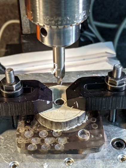
The fixture on the other end started as a scrap of polycarbonate bandsawed into a disk with a hole center-drilled in the middle:
Pipe end lathe fixture – center drilling
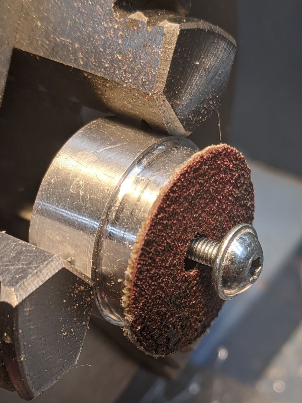
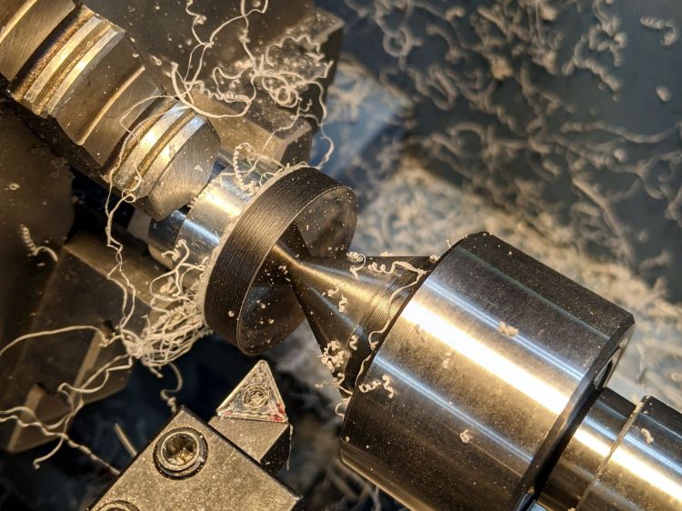
Stick it onto a disk turning fixture and sissy-cut the OD down a little smaller than the eventual tube OD:
Pipe end lathe fixture – turning OD
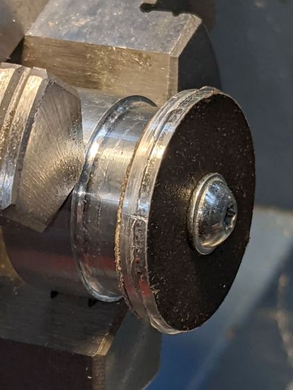
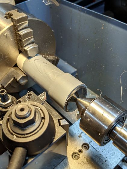
Turn the end down to fit the tube ID, flip it around to center-drill the other side, stick it into the tube, and finally finish the job:
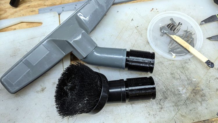
Dirt Devil adapter – pipe fixture
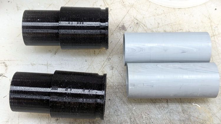
The nice layering effect along the tube probably comes from molding the conduit from recycled PVC with no particular concern for color matching.
A family portrait of the fixtures with a finished adapter:
Dirt Devil adapter – fixtures
A fine chunk of Quality Shop Time: solid modeling, 3D printing, mini-lathe turning, and even some coordinate drilling on the Sherline.
A smear of epoxy around the interior holds the tube in place:
Dirt Devil adapters – assembled
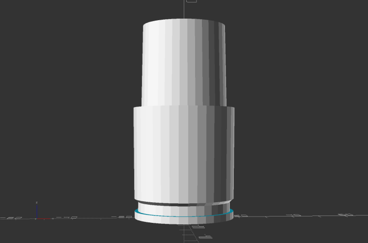
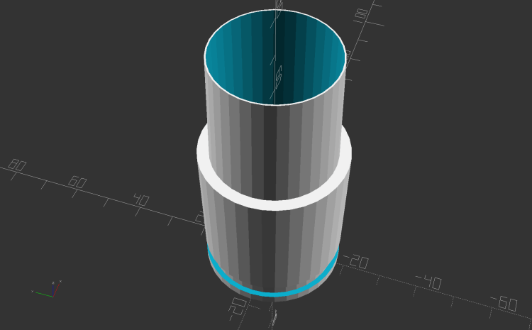
Building the critical dimensions with a 3D printed part simplified the project, because I could (and did!) tweak the OpenSCAD code to match the tapers to the tools. Turning four of those tubes from a chunk of PVC conduit, however, makes a story for another day.
This file contains hidden or bidirectional Unicode text that may be interpreted or compiled differently than what appears below. To review, open the file in an editor that reveals hidden Unicode characters.
Learn more about bidirectional Unicode characters
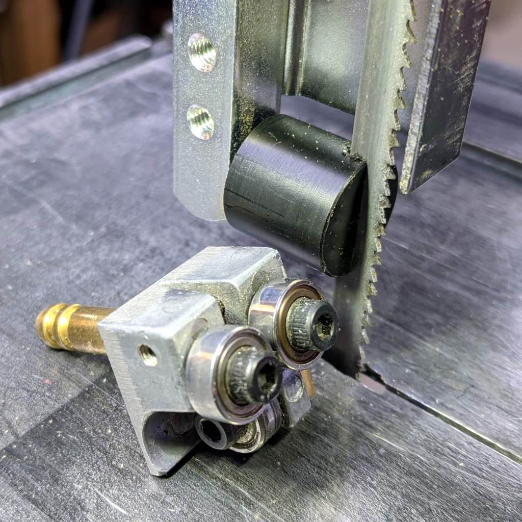
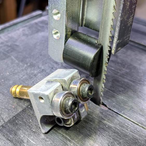
It’s basically the same as the lower blade guide, except coming from a stick of 5/8 inch acetal. A scant 6 mm stem goes into the vertical square rod, with a flat matching the setscrew coming up from the bottom to hold it in proper alignment.
I came within a heartbeat of cutting the slot parallel to the flat.
It worked OK while cutting a chunk of stout aluminum tube: so far, so good!
The impressive chunk of hardware is the OEM blade guide, with the brass tube for coolant flow all over the bearings. It’s mostly intended for use with the diamond blade, so I’ll swap it back in when I finally get around to cutting some slate for base plates.