The Smell of Molten Projects in the Morning

Ed Nisley's Blog: Shop notes, electronics, firmware, machinery, 3D printing, laser cuttery, and curiosities. Contents: 100% human thinking, 0% AI slop.

Tag: M2

Using and tweaking a Makergear M2 3D printer

  • Dirt Devil Vacuum Tool Adapters

    Dirt Devil Vacuum Tool Adapters

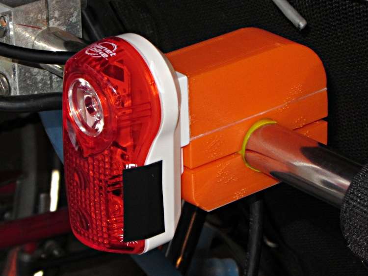
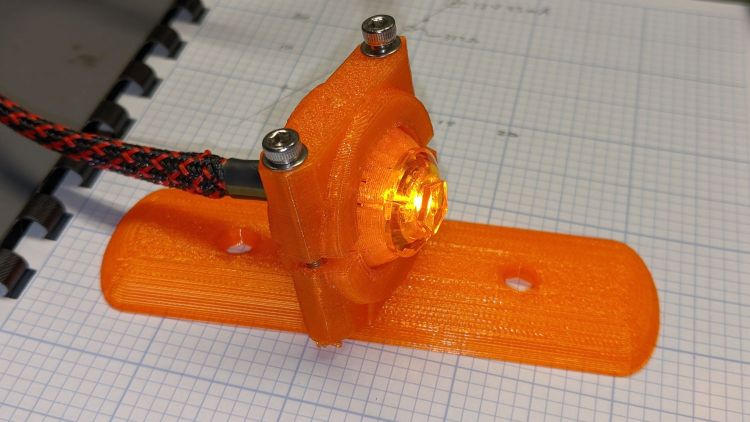
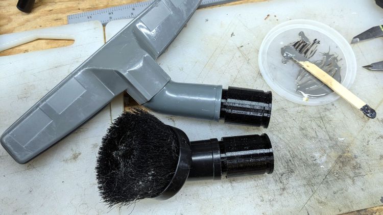
    Being the domain expert for adapters between a new vacuum cleaner and old tools, this made sense (even though it’s not our vacuum):

    Dirt Devil Nozzle Bushing - solid model
    Dirt Devil Nozzle Bushing – solid model

    The notch snaps into a Dirt Devil Power Stick vacuum cleaner and the tapered end fits a variety of old tools for other vacuum cleaners:

    Dirt Devil Nozzle Bushing top view - solid model
    Dirt Devil Nozzle Bushing top view – solid model

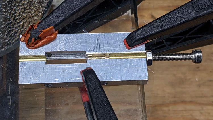
    Having some experience breaking thin-walled adapters, these have reinforcement from a PVC tube:

    Dirt Devil adapter - parts
    Dirt Devil adapter – parts

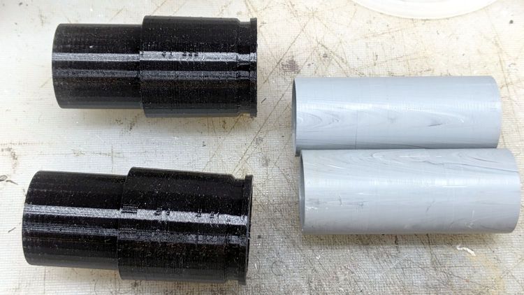
    A smear of epoxy around the interior holds the tube in place:

    Dirt Devil adapters - assembled
    Dirt Devil adapters – assembled

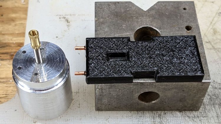
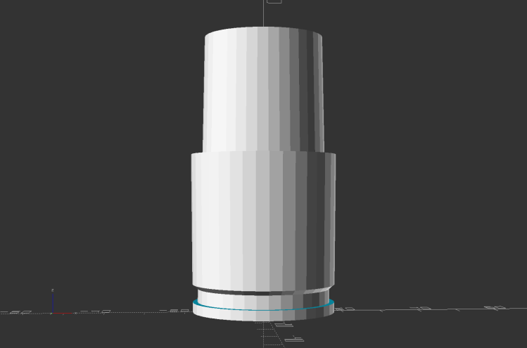
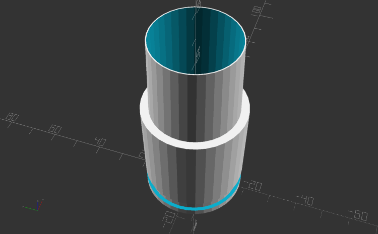
    Building the critical dimensions with a 3D printed part simplified the project, because I could (and did!) tweak the OpenSCAD code to match the tapers to the tools. Turning four of those tubes from a chunk of PVC conduit, however, makes a story for another day.

    The OpenSCAD source code as a GitHub Gist:

    // Dirt Devil nozzle adapter
    // Ed Nisley KE4ZNU 2021-10
    // Tool taper shift
    Finesse = -0.1; // [-0.5:0.1:0.5]
    // PVC pipe liner
    PipeOD = 28.5;
    /* [Hidden] */
    //- Extrusion parameters
    ThreadThick = 0.25;
    ThreadWidth = 0.40;
    HoleWindage = 0.2;
    function IntegerMultiple(Size,Unit) = Unit * ceil(Size / Unit);
    Protrusion = 0.1; // make holes end cleanly
    //———————-
    // Dimensions
    TAPER_MIN = 0;
    TAPER_MAX = 1;
    TAPER_LENGTH = 2;
    Socket = [36.0,37.0,40.0];
    LockringDia = 33.5;
    LockringWidth = 4.5;
    LockringOffset = 2.5;
    Tool = [Finesse,Finesse,0] + [30.0,31.1,30.0];
    AdapterOAL = Socket[TAPER_LENGTH] + Tool[TAPER_LENGTH];
    NumSides = 36;
    $fn = NumSides;
    //———————-
    // Useful routines
    module PolyCyl(Dia,Height,ForceSides=0) { // based on nophead's polyholes
    Sides = (ForceSides != 0) ? ForceSides : (ceil(Dia) + 2);
    FixDia = Dia / cos(180/Sides);
    cylinder(r=(FixDia + HoleWindage)/2,h=Height,$fn=Sides);
    }
    //——————-
    // Define it!
    module Adapter() {
    difference() {
    union() {
    difference() {
    cylinder(d1=Socket[TAPER_MIN],d2=Socket[TAPER_MAX],h=Socket[TAPER_LENGTH]);
    translate([0,0,LockringOffset])
    cylinder(d=2*Socket[TAPER_MAX],h=LockringWidth);
    }
    cylinder(d=LockringDia,h=Socket[TAPER_LENGTH]);
    translate([0,0,LockringOffset + 0.75*LockringWidth])
    cylinder(d1=LockringDia,d2=Socket[TAPER_MIN],h=0.25*LockringWidth);
    translate([0,0,Socket[TAPER_LENGTH]])
    cylinder(d1=Tool[TAPER_MAX],d2=Tool[TAPER_MIN],h=Tool[TAPER_LENGTH]);
    }
    translate([0,0,-Protrusion])
    PolyCyl(PipeOD,AdapterOAL + 2*Protrusion,NumSides);
    }
    }
    //———————-
    // Build it!
    Adapter();

    The taper in the code almost certainly won’t fit whatever tool you have: measure thrice, print twice, and maybe fit once …

  • Tour Easy Rear Running Light: Circuit Support Plate

    Tour Easy Rear Running Light: Circuit Support Plate

    Building the circuit support plate for the amber front running light was entirely too fiddly:

    1 W LED Running Light - baseplate dry assembly
    1 W LED Running Light – baseplate dry assembly

    This was definitely easier:

    Running Light Circuit Plate - solid model
    Running Light Circuit Plate – solid model

    Two pins fit in the small holes to align it with the LED heatsink, with an M3 stud and brass insert holding it in place:

    Tour Easy Rear Running Light - circuit plate attachment
    Tour Easy Rear Running Light – circuit plate attachment

    The rectangular hole around the insert let me glop urethane adhesive over it to lock it into the plate, with more goop on the screw and pins to unify heatsink and plate.

    The LED wires now emerge from the heatsink on the same side of the plate, simplifying the connections to the MP1584 regulator and current-sense resistor:

    Tour Easy Rear Running Light - regulator wiring
    Tour Easy Rear Running Light – regulator wiring

    The paralleled 5.1 Ω and 3.3 Ω resistors form a 2.0 Ω resistor setting the LED current to 400 mA = 1 W at 2.6 V forward drop. They’re 1 W resistors dissipating a total of 320 mW and get barely warm.

    The resistors and wires are stuck in place with clear adhesive, so things shouldn’t rattle around too much.

    The OpenSCAD source code as a GitHub Gist:

    // Circuit plate for Tour Easy running lights
    // Ed Nisley – KE4ZNU – 2021-09
    /* [Hidden] */
    ThreadThick = 0.25;
    ThreadWidth = 0.40;
    HoleWindage = 0.2;
    Protrusion = 0.1; // make holes end cleanly
    function IntegerMultiple(Size,Unit) = Unit * ceil(Size / Unit);
    ID = 0;
    OD = 1;
    LENGTH = 2;
    inch = 25.4;
    //———————-
    // Dimensions
    // Light case along X axis
    LightID = 23.0;
    WallThick = 2.0;
    Screw = [3.0,6.8,4.0]; // M3 OD=washer, length=nut + washers
    Insert = [3.0,4.2,8.0]; // splined brass insert, minus splines
    InsertOffset = 10.0; // insert from heatsink end
    PinOD = 1.6; // alignment pins
    PinOC = 14.0;
    PinDepth = 5.0;
    Plate = [50.0,LightID,Insert[OD] + 4*ThreadThick]; // overall plate size
    WirePort = [10.0,3.0,2*Plate.z];
    NumSides = 2*3*4;
    //———————-
    // Useful routines
    module PolyCyl(Dia,Height,ForceSides=0) { // based on nophead's polyholes
    Sides = (ForceSides != 0) ? ForceSides : (ceil(Dia) + 2);
    FixDia = Dia / cos(180/Sides);
    cylinder(r=(FixDia + HoleWindage)/2,
    h=Height,
    $fn=Sides);
    }
    // Circuit plate
    module Plate() {
    difference() {
    intersection() {
    cube(Plate,center=true);
    rotate([0,90,0])
    cylinder(d=LightID,h=2*Plate.x,$fn=NumSides,center=true);
    }
    rotate([0,90,0]) rotate(180/6)
    translate([0,0,-Plate.x])
    PolyCyl(Screw[ID],2*Plate.x,6);
    rotate([0,90,0]) rotate(180/6)
    translate([0,0,-Plate.x/2 – Protrusion])
    PolyCyl(Insert[OD],Insert[LENGTH] + InsertOffset + Protrusion,6);
    translate([-Plate.x/2 + InsertOffset + Insert[LENGTH]/2,0,Plate.z/2])
    cube([Insert[LENGTH],Insert[OD],Plate.z],center=true);
    for (j=[-1,1])
    translate([-Plate.x/2,j*PinOC/2,0])
    rotate([0,90,0]) rotate(180/6)
    translate([0,0,-PinDepth])
    PolyCyl(PinOD,2*PinDepth,6);
    for (j=[-1,1])
    translate([0,j*(Plate.y/2 – WirePort.y/2),0])
    cube(WirePort,center=true);
    }
    }
    //- Build it
    Plate();

  • Rear Running Light: Tour Easy Seat Clamp

    Rear Running Light: Tour Easy Seat Clamp

    With the amber front running light blinking away, it’s time to replace the decade-old Planet Bike Superflash behind the seat:

    Superflash on Tour Easy
    Superflash on Tour Easy

    The new mount descends directly from the clamps holding the fairing strut on the handlebars and various hose clamps:

    Rear Running Light Seat Clamp - solid model
    Rear Running Light Seat Clamp – solid model

    The central block has two quartets of brass inserts epoxied inside:

    Rear Running Light Seat Clamp - sectioned - solid model
    Rear Running Light Seat Clamp – sectioned – solid model

    That means I can install the light, then mount the whole affair on the bike, without holding everything together while fiddling with overly long screws.

    A trial fit with the not-yet-cut-to-length 25.3 (-ish) PVC pipe body tube:

    Rear Running Light - Tour Easy seat clamp trial fit
    Rear Running Light – Tour Easy seat clamp trial fit

    The aluminum plates have the standard used-car finish: nice polish over deep scratches.

    Although I’ve been thinking of mounting the light below the seat rail, as shown, it can also sit above the rail.

    Mary hauls seedlings and suchlike to the garden in a plastic drawer bungied to the rack, with the SuperFlash serving as an anchor point; this light may need fine tuning for that purpose.

    The OpenSCAD source code as a GitHub Gist:

    // Rear running light clamp for Tour Easy seat strut
    // Ed Nisley – KE4ZNU – 2021-09
    Layout = "Show"; // [Show,Build,Block]
    Section = true;
    /* [Hidden] */
    ThreadThick = 0.25;
    ThreadWidth = 0.40;
    HoleWindage = 0.2;
    Protrusion = 0.1; // make holes end cleanly
    function IntegerMultiple(Size,Unit) = Unit * ceil(Size / Unit);
    ID = 0;
    OD = 1;
    LENGTH = 2;
    inch = 25.4;
    //———————-
    // Dimensions
    // Light case along X axis, seat strut along Y, Z=0 at strut centerline
    LightOD = 25.4 + HoleWindage;
    StrutOD = 5/8 * inch + HoleWindage;
    PlateThick = 1/16 * inch;
    WallThick = 2.0;
    Kerf = ThreadThick;
    Screw = [3.0,6.8,4.0]; // M3 OD=washer, length=nut + washers
    Insert = [3.0,5.4,8.0 + 1.0]; // splined brass insert
    RoundRadius = IntegerMultiple(Screw[OD]/2,0.5); // corner rounding
    ScrewOC = [IntegerMultiple(StrutOD + 2*WallThick + Screw[ID],1.0),
    IntegerMultiple(LightOD + 2*WallThick + Screw[ID],1.0)];
    echo(str("Screw OC: ",ScrewOC));
    BlockSize = [ScrewOC.x + Insert[OD] + 2*WallThick,
    ScrewOC.y + Insert[OD] + 2*WallThick,
    LightOD + StrutOD + 3*WallThick];
    echo(str("Block: ",BlockSize));
    BaseOffset = -(WallThick + LightOD/2); // block bottom to centerline
    StrutOffset = LightOD/2 + WallThick + StrutOD/2; // light centerline to strut centerline
    echo(str("Strut screw min: ",IntegerMultiple(PlateThick + WallThick + StrutOD/2 + Insert[LENGTH]/2,1.0)));
    echo(str("Light screw min: ",IntegerMultiple(PlateThick + WallThick + LightOD/2 + Insert[LENGTH]/2,1.0)));
    NumSides = 2*3*4;
    //———————-
    // Useful routines
    module PolyCyl(Dia,Height,ForceSides=0) { // based on nophead's polyholes
    Sides = (ForceSides != 0) ? ForceSides : (ceil(Dia) + 2);
    FixDia = Dia / cos(180/Sides);
    cylinder(r=(FixDia + HoleWindage)/2,
    h=Height,
    $fn=Sides);
    }
    // Block with light along X axis
    module Block() {
    difference() {
    hull()
    for (i=[-1,1], j=[-1,1])
    translate([i*(BlockSize.x/2 – RoundRadius),j*(BlockSize.y/2 – RoundRadius),BaseOffset])
    cylinder(r=RoundRadius,h=BlockSize.z,$fn=NumSides);
    for (i=[-1,1], j=[-1,1])
    translate([i*ScrewOC.x/2,j*ScrewOC.y/2,BaseOffset – Protrusion])
    rotate(180/8)
    PolyCyl(Screw[ID],BlockSize.z + 2*Protrusion,8);
    for (i=[-1,1], j=[-1,1])
    translate([i*ScrewOC.x/2,j*ScrewOC.y/2,0]) {
    translate([0,0,-Protrusion])
    rotate(180/8)
    PolyCyl(Insert[OD],Insert[LENGTH] + 1*Protrusion,8);
    translate([0,0,(StrutOffset – Insert[LENGTH] – Kerf/2 + Protrusion)])
    rotate(180/8)
    PolyCyl(Insert[OD],Insert[LENGTH] + 1*Protrusion,8);
    }
    translate([-BlockSize.x,0,0])
    rotate([0,90,0])
    cylinder(d=LightOD,h=2*BlockSize.x,$fn=NumSides);
    translate([0,BlockSize.y,StrutOffset])
    rotate([90,0,0])
    cylinder(d=StrutOD,h=2*BlockSize.y,$fn=NumSides);
    translate([0,0,StrutOffset])
    cube([2*BlockSize.x,2*BlockSize.y,Kerf],center=true);
    cube([2*BlockSize.x,2*BlockSize.y,Kerf],center=true);
    }
    }
    //- Build it
    if (Layout == "Block")
    if (Section)
    difference() {
    Block();
    rotate(atan(ScrewOC.y/ScrewOC.x))
    translate([0,BlockSize.y,0])
    cube(2*BlockSize,center=true);
    }
    else
    Block();
    if (Layout == "Show") {
    Block();
    color("Green",0.25)
    translate([-BlockSize.x,0,0])
    rotate([0,90,0])
    cylinder(d=LightOD,h=2*BlockSize.x,$fn=NumSides);
    color("Green",0.25)
    translate([0,BlockSize.y,StrutOffset])
    rotate([90,0,0])
    cylinder(d=StrutOD,h=2*BlockSize.y,$fn=NumSides);
    }
    if (Layout == "Build") {
    translate([-1.2*BlockSize.x,0,-BaseOffset])
    difference() {
    Block();
    translate([0,0,BlockSize.z])
    cube(2*BlockSize,center=true);
    }
    translate([1.2*BlockSize.x,0,StrutOD/2 + WallThick])
    difference() {
    rotate([180,0,0])
    translate([0,0,-StrutOffset])
    Block();
    translate([0,0,BlockSize.z])
    cube(2*BlockSize,center=true);
    }
    translate([0,0,StrutOffset – Kerf/2])
    rotate([180,0,0])
    intersection() {
    Block();
    translate([0,0,StrutOffset/2])
    cube([2*BlockSize.x,2*BlockSize.y,StrutOffset],center=true);
    }
    }

  • Tour Easy 1 W Amber Running Light: Firmware

    Tour Easy 1 W Amber Running Light: Firmware

    Rather than conjure a domain specific language to blink an LED, it’s easier to use Morse code:

    Herewith, Arduino source code using Mark Fickett’s Morse library to blink an amber running light:

    // Tour Easy Running Light
    // Ed Nisley - KE4ZNU
    // September 2021
    
    #include <morse.h>
    
    #define PIN_OUTPUT	13
    
    LEDMorseSender Morser(PIN_OUTPUT,(float)10.0);
    
    void setup()
    {
    	Morser.setup();
    
        Morser.setMessage(String("qst de ke4znu "));
        Morser.sendBlocking();
    
    //    Morser.setWPM((float)3.0);
        Morser.setSpeed(50);
    	Morser.setMessage(String("s   "));
    }
    
    void loop()
    {
    	if (!Morser.continueSending())
    		Morser.startSending();
    
    }
    

    Bonus: a trivially easy ID string.

    A dit time of 50 ms produces a brief flash that’s probably about as fast as it can be, given that the regulator must ramp the LED current up from zero after its Enable input goes high. In round numbers, a 50ms dit corresponds to 24 WPM Morse.

    Each of the three blanks after the “s” produces a seven element word space to keep the blinks from running together.

    Sending “b ” (two blanks) with a 75 ms dit time may be more noticeable. You should tune for maximum conspicuity on your rides.

    1 W Amber Running Light - installed front
    1 W Amber Running Light – installed front

    On our first ride, Mary got a friendly wave from a motorcyclist, an approving toot from a driver, and several “you go first” gestures at intersections.

    Works for us …

  • Seedling Shelter Frame Deployment

    Seedling Shelter Frame Deployment

    Mary bound up a mesh cover for the shelter frame and deployed it to protect some yummy seedlings:

    Seedling Mesh Shelter - installed
    Seedling Mesh Shelter – installed

    Those will become the next round of lunchtime sandwiches:

    Turkey Sandwich with Excessive Lettuce
    Turkey Sandwich with Excessive Lettuce

    It’s a quarter-pounder: 4 oz of turkey, 4 oz of lettuce, and a layer of Swiss and good stinky Provolone cheese. Yum!

  • Vacuum Tube Lights: Urethane Coated Plate Cap

    Vacuum Tube Lights: Urethane Coated Plate Cap

    With a generous dollop of JB Plastic Bonder left over from a set of Bafang brake sensor magnets, I tried coating the ersatz plate cap of a triode tube:

    Triode - urethane coated plate cap
    Triode – urethane coated plate cap

    That’s the result after leaving it hanging upside-down while it cured to push all the drips to the top.

    For comparison, the uncoated cap back in the day:

    Triode - plate cap plug
    Triode – plate cap plug

    Seeing as how the urethane is an adhesive, not a coating, I’d say it looks about as bad as expected.

    As with all 3D printed things, one must embrace imperfections and striations, rather than endlessly strive for perfection.

    Now, if I had a resin printer …

  • Tour Easy: Amber Running Light

    Tour Easy: Amber Running Light

    Having seen a few bikes with amber “headlights” and being desirous of reducing the number of batteries on Mary’s bike, this seems like an obvious first step:

    Fairing Mounted Side Marker - First Light
    Fairing Mounted Side Marker – First Light

    It descends from the fairing flashlight mount with an entry to suit a 15 mm truck side marker body:

    LightBodies = [
      ["AnkerLC90",26.6,48.0],
      ["AnkerLC40",26.6,55.0],
      ["J5TactV2",25.0,30.0],
      ["InnovaX5",22.0,55.0],
      ["Sidemarker",15.0,20.0],
      ["Laser",10.0,30.0],
    ];
    

    The rest of the code gets a few cleanups you’d expect when you compile code untouched for a few years using the latest OpenSCAD.

    The markers are allegedly DOT rated, which matters not for my use case: SAEP2PCDOT.

    The mount is grossly overqualified for a wide-beam light with little need for aiming:

    Fairing Mounted Side Marker - test light
    Fairing Mounted Side Marker – test light

    Eventually, the marker should slip into a prealigned cylindrical holder, with a dab of epoxy to keep it there.

    The lights are a buck apiece, so there’s no reason to form a deep emotional attachment. They are the usual poorly molded and badly assembled crap, although the next step up from a nominally reputable supplier is a factor of five more expensive.

    It’s generated for the left side of the fairing, although I think having a pair of them would improve conspicuity:

    Fairing Mounted Side Marker - installed
    Fairing Mounted Side Marker – installed

    Being automotive, it runs from a 12 V supply, which comes from a boost converter driven by the Bafang 6 V headlight output. The absurdity of bucking a 48 V lithium battery to a 6V switched headlight output, then boosting it to 12 V to drive a single amber LED with a 1.5 V forward drop does not escape me.

    It’s possible to slice the lens off (using a lathe), remove / replace the resistor, then glue it back together, which would be worthwhile if you were intending to drive it from, say, an Arduino-ish microcontroller to get a unique blink pattern.

    Given the overall lack of build quality, it might make more sense to slap a condenser lens in front of a Piranha LED.

    Bonus: contrary to what you (well, I) might expect, the black lead is positive and the white lead is negative.