It should be possible to sense the filament diameter with a cheap webcam and some optics:

The general idea:
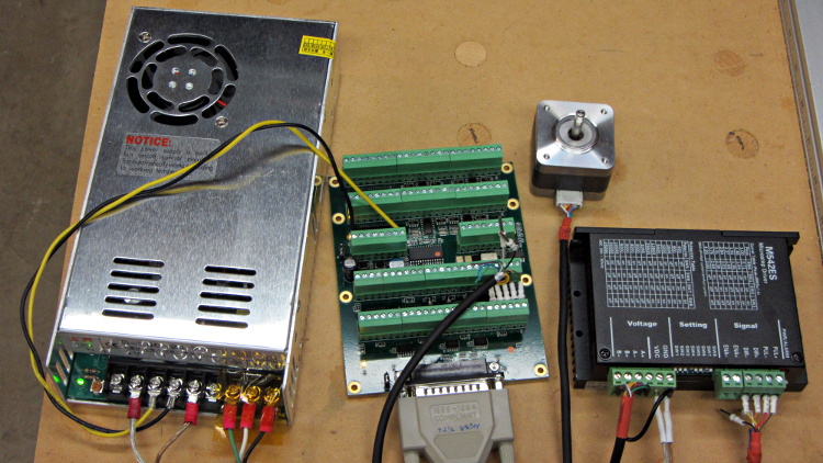
Given that LinuxCNC runs on a bone-stock PC, you can plug in a stock USB webcam and capture pictures (I have done this already). Because LinuxCNC isolates the motion control in a hard real time process, you can run heavy metal image manipulation code in userland (think ImageMagick) without affecting the motors.
So you can put a macro lens in front of a webcam (like that macro lens holder) and mount it just above the extruder with suitable lighting to give a high-contrast view of the filament. Set it so the filament diameter maps to about 1/4 of the width of the image, for reasons explained below.
For a crappy camera with 640×480 resolution, this gives you 160 pixel / 1.75 mm filament = 91 pixel/mm → about 0.01 mm resolution = 0.6%. Use a better camera, get better resolution: 1280 pixel = 0.3% resolution.
That gives you roughly 1% or 0.5% resolution in area. This is pretty close to the holy grail for DIY filament diameter measurement.
Add two first-surface mirrors / prisms aligned at right angles, so that the camera sees three views of the filament: straight on, plus two views at right angles, adjacent to the main view. Set the optics so they’re all about 1/4 of the image width, to produce an image with three parts filament and one part high-contrast background separating them. This is the ideal, reality will be messier.
Figure 1 shows an obvious arrangement, the mirrors in Figure 2 give more equal distances.
You could align the mirrors to provide three views at mutual 120° angles, which would equalize the distances and give you three identical angles for roundness computation, should that matter.
Diameter measurement process:
- Extract one (*) scan line across the image.
- Convert to binary pixels: 1 = filament, 0 = background, perhaps with ImageMagick auto thresholding.
- Add pixel values across the line, divide by 3, multiply by mm/pixel → average filament diameter.
- Done!
Adding binary pixels is easy: it’s just the histogram, which ImageMagick does in one step. Dump data to a file / pipe, process it with Python. It all feeds into a LinuxCNC HAL component, which may constrain the language to C / Python / something else.
(*) You can get vertical averaging over a known filament length, essentially for free. Extract three (or more) scan lines, process as above, divide by 3 (or more), and you get a nicely averaged average.
Win: the image is insensitive to position / motion / vibration within reasonable limits, because you’re doing the counting on pixel values, not filament position. The camera can mount near, but not on, the extruder, so you can measure the filament just above the drive motor without cooking the optics or vibrating the camera to death.
Win: it’s non-contacting, so there’s not much to get dirty
Win: you get multiple simultaneous diameter measurements around one slice of the filament
You could mount the camera + optics at one end of the printer’s axis (on the M2, the X axis). Drive the extruder to a known X position, take a picture of the straight-on view, drive to another position, take a picture of the mirrored views, and you have two pictures in perfect focus. Combine & process as above.
You can do that every now and again, because any reasonable filament won’t vary that much over a few tens of millimeters. Maybe you do it once per layer, as part of the Z step process?
You could generalize this to a filament QC instrument that isn’t on the printer itself: stream the filament from spool to spool while measuring it every 10 mm, report the statistics. That measurement could run without stopping, because you don’t reposition the filament between measurements: it’s all fixed-focus against a known background. You could have decent roller guides for the filament to ensure it’s in a known position.
Heck, that instrument could produce a huge calibration file that gives diameter / roundness vs. position along the entire length of the filament. Use it to accept/reject incoming plastic supplies or, even better, feed the data into the printer along with the spool to calibrate the extrusion on the fly without fancy optics or measurements.
Dan wonders if this might be patented. I’m sure it is: I’m nowhere near as bright as the average engineering bear at a company that’s been spending Real Money for three decades. My working assumption: all the knowledge is out there, behind a barrier I can’t see through or reach around: there’s no point in looking for it beyond a casual Google search on the obvious terms that, so far, hasn’t produced anything similar.
Memo to Self: Might even be marketable, right up until they crush me like a bug…