Ed Nisley's Blog: Shop notes, electronics, firmware, machinery, 3D printing, laser cuttery, and curiosities. Contents: 100% human thinking, 0% AI slop.
This doesn’t happen very often, but, after a few road trips and some jostling around, the M2’s platform was definitely out of alignment: the first layer came out generally too thin, with the X-Y+ quadrant very much too thin.
I tried a quick and dirty adjustment that didn’t produce meaningful results, then broke out the Starrett Taper Gauge and did it right.
Jog around measuring the height of the nozzle above the platform
Adjust screws to reduce variation
Change Z offset in startup G-Code
Run off a few test patterns to get the platform heated
Measure actual thickness
Change Z offset to get the right answer
Done!
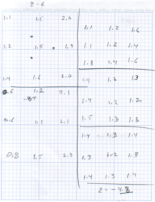
This progression of cold measurements, read top-to-bottom, left column first, shows the observed nozzle height above the platform around the edges and at the center:
M2 Platform Leveling Progression – 2014-06-30
The final measurements seem to indicate the glass plate is 0.2 mm convex in the center, but I wouldn’t trust the measurements to that level of accuracy. It’s probably bowed upward, but it’s certainly close enough.
The cold measurements suggest that the Z offset should be -4.80 mm, but the measurements on the hot platform with actual extrusion threads showed that -4.50 mm produced the correct thicknesses.
It’s not clear automating the movements would produce better or faster results than just manually jogging the nozzle around the platform, particularly since it happens only every few months.
This would be easier with the Z offset stored in the EEPROM and some modified startup G-Code to retrieve it.
Given the troubles we’ve had with that thing, using it as an input device isn’t going to happen.
More modern “digital” sewing machines seem to use linear potentiometers or analog optical sensors; retrofitting that old housing seems difficult, at best, because the actuator has barely 15 mm of travel. I’m sure somebody could conjure up a bell crank to amplify the mechanical motion, but that ain’t me.
This doodle shows the rudiments of an alternative:
Hall effect distance sensor – original doodle
The general idea is to have the existing cross bar / roller move a magnet relative to an analog Hall effect sensor: closer to sensor = higher magnetic field = higher sensor output voltage. Ideally, the magnet provides enough field to max out the sensor just before the pedal reaches the limit of its travel, so the magnet never quite touches the sensor.
An optical wedge would serve a similar function, but this pretty much eliminates all the critical alignment & focusing & friction issues. Plus, I have a bunch of analog Hall effect sensors…
I have a stock of telescoping brass tubing, so the inner tube slides over the 4 mm screw that threads into the existing hardware, replacing the old shaft. That tube slides inside an outer tube that’s aligned in a block attached to the pedal frame; an epoxy blob holds it in position. The inner tube should have a nut on the left end to allow adjusting the rest position.
The Hall effect sensors have a zero-field bias at about VCC/2, so a smaller opposing (and fixed) bias magnet on the far side of the sensor pushes the output voltage to the lower limit. The adjusting screw on that side sets the bias level, if that’s needed.
A spring that’s not shown pushes the cross bar away from the block holding the outer tube and sensor; that’s what restores the magnet to its rest position when the pedal is up.
This being the age of rapid prototyping:
Foot Control Sensor Mount – solid model – top
The bottom view shows an opening for the epoxy blob halfway between the rear wall and the opening for the magnet and Hall effect sensor:
Foot Control Sensor Mount – solid model – bottom
Two bosses inside the pedal base fit into those rectangular cutouts, with the centerline of the tubing at the top of the bosses.
The inner brass tube holds the outer tube in the proper alignment while the epoxy slab cures:
Kenmore 158 – Hall speed control – tubing fit
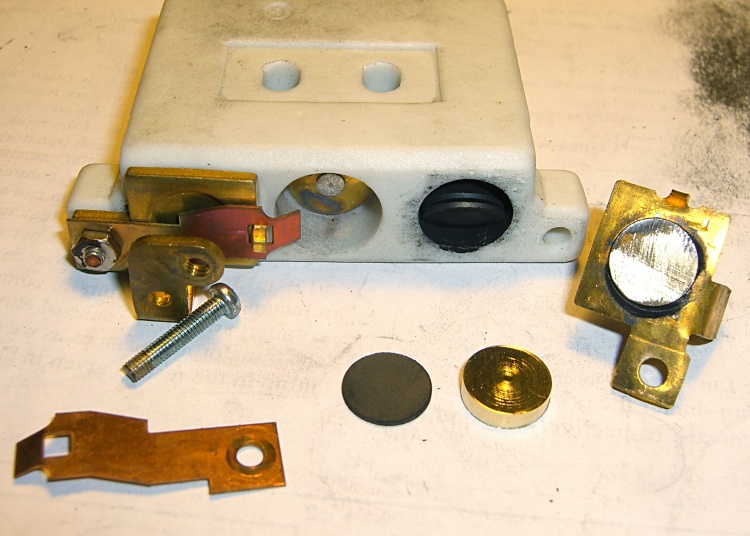
Fortunately, two of the neodymium magnets in my collection worked out perfectly as the main and bias magnets. The smaller bias magnet just barely saturates the output when epoxied to the back of the sensor and the larger magnet has about 15 mm of active range.
The assembly sequence required half a dozen separate epoxy applications; I used quick-curing clear epoxy, rather than my usual JB Weld, because this isn’t the place for a steel filled epoxy. The final step put a washer on the back of the inner tube to hold the spring in place, with the Hall effect sensor invisible under the wad of closed-cell foam at the bottom:
Kenmore 158 – Hall speed control – epoxy curing
The spring comes from the Big Box o’ Medium Springs, which contains a few more just like it.
That solid model and the OpenSCAD code below include several refinements that don’t appear in the photos. In particular, the graceful slope on the top front will look a whole lot better than the abrasive adjustment required to fit the chunky first version into the pedal case:
Kenmore 158 – Hall speed control – prototype interior
On the other paw, that’s what rapid prototyping is all about. I had no way to measure that dimension, but building one to figure it worked pretty well.
Things that may / will need tweaking:
The centerline of the tubing lies on the same plane as the tops of the bosses under those three screws, but the bosses are not particularly flat. Perhaps some setscrews to fine-tune the height and front-to-back tilt angle?
The sketch had adjustable magnet positions; the as-built hardware doesn’t. It’s not clear they’re needed, although that depends on having exactly the right magnets.
The screws are #4 sheet metal and fit nicely into the metric holes; the original screws held a thin aluminum bracket in place, not that chunky block. I could recess the heads, but …
A 3D printed clamp holding the cable and strain relief bushing in place would be cuter than the sheet metal strap I bashed from scrap.
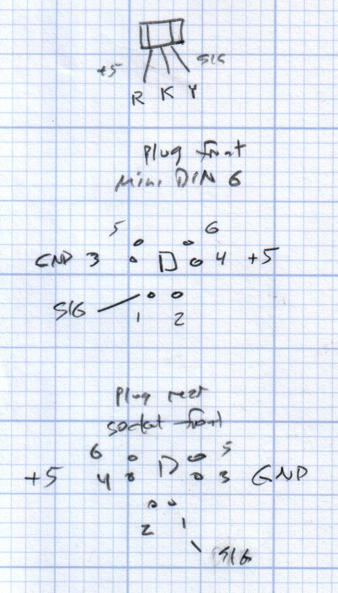
The far end of the cable terminates in a 6-pin mini-DIN connector, left over from the days when PCs (remember PCs?) had PS/2 mice & keyboards:
Kenmore 158 Improved Speed Control Pedal – cable wiring diagram
I’ll eventually put the emitter resistor into the circuit; these sensors work fine without it. The cable provides electrostatic shielding and I’m hoping the impedance is low enough that the motor won’t induce any noise. In any event, some low-pass filtering won’t slow down the response enough to notice.
Next, some measurements…
The OpenSCAD source code:
// Foot Control Sensor Mount
// Ed Nisley - KE4ZNU - June 2014

Layout = "Show";			// Plate Build Show

//- Extrusion parameters must match reality!
//  Print with 4 shells and 3 solid layers

ThreadThick = 0.20;
ThreadWidth = 0.40;

HoleWindage = 0.2;			// extra clearance

Protrusion = 0.1;			// make holes end cleanly

AlignPinOD = 1.70;			// assembly alignment pins: filament dia

function IntegerMultiple(Size,Unit) = Unit * ceil(Size / Unit);

//----------------------
// Dimensions
// Origin at center front edge of plate
//  Z = bottom surface

PlateSize = [85.0,53.0,15.0];						// overall plate size
MidZ = PlateSize[2]/2;								//  height of spring midline
PlateCornerRadius = 1.5;

FrontBevel = [0.0,15.0,5.5];						// Y from front, Z from centerline

ScrewHolesOC = [[-75.0/2,(37.0 - 14.0/2)],[-75.0/2,(37.0 + 14.0/2)],[75.0/2,37.0]];
ScrewHoleDia = 4.0;									// allow alignment slop around 3 mm / #4 screws

BossSize = [[12.0,28.0],[12.0,27.0]];				// mounting bosses: L R
BossOC = [[-75.0/2,37.0],[75.0/2,37.0]];

Stroke = 15.0;										// foot pedal actuation distance

Bushing = [5.6,23.0];								// outer brass tube
MainMagnet = [10.0,5.0];							// magnet on pushrod
BiasMagnet = [5.0,2.0];								// bias magnet behind Hall effect sensor
Spring = [9.0,8.0];									// recess for pushrod retracting spring
Washer = [10.0,1.0];								// recess for washer atop pushrod

OD = 0;												// subscripts for cylindrical objects
LEN = 1;

SensorThick = 2.0;									// Hall effect sensor on bias magnet
FilletLength = 0.75;								// glue fillet on main magnet

//----------------------
// Useful routines

module PolyCyl(Dia,Height,ForceSides=0) {			// based on nophead's polyholes

  Sides = (ForceSides != 0) ? ForceSides : (ceil(Dia) + 2);

  FixDia = Dia / cos(180/Sides);

  cylinder(r=(FixDia + HoleWindage)/2,
           h=Height,
           $fn=Sides);
}

module ShowPegGrid(Space = 10.0,Size = 1.0) {

  RangeX = floor(100 / Space);
  RangeY = floor(125 / Space);

	for (x=[-RangeX:RangeX])
	  for (y=[-RangeY:RangeY])
		translate([x*Space,y*Space,Size/2])
		  %cube(Size,center=true);

}

//----------------------
// Basic plate shape

module Plate() {

R = PlateCornerRadius;
Px = PlateSize[0]/2 - R;
Py = PlateSize[1] - R;
Sides = 4*4;

BevelAngle = atan2((MidZ - FrontBevel[2]),FrontBevel[1]);

echo("Bevel angle: ",BevelAngle);

	difference() {
		linear_extrude(height = PlateSize[2]) {
			hull() {
				translate([-Px,Py])
					circle(r=R,$fn=Sides);
				translate([Px,Py])
					circle(r=R,$fn=Sides);
				translate([Px,R])
					circle(r=R,$fn=Sides);
				translate([-(20-R),R])			// avoid left front boss
					circle(r=R,$fn=Sides);
				translate([-Px,20+R])			// avoid left front boss
					circle(r=R,$fn=Sides);
			}
		}

		translate([0,0,-Protrusion])						// screw bosses
			linear_extrude(height = (MidZ + Protrusion),convexity=2)
				for (i=[0:1])
					translate(BossOC[i])
						square(BossSize[i],center=true);

		translate([0,0,-Protrusion])						// plate mounting screws
			linear_extrude(height = 2*PlateSize[2] + Protrusion,convexity=3)
				for (i=[0:2])
					translate(ScrewHolesOC[i])
						rotate(180/6)
							circle(d=ScrewHoleDia,$fn=6);

		translate([0,0,MidZ + FrontBevel[2]])		// Front bevel
			rotate([BevelAngle,0,0])
				translate([0,0,PlateSize[2]])
					cube(2*PlateSize,center=true);

	}
}

//----------------------
// Modify plate for position sensor hardware

module Sensor() {

GluePort = [1.5*Bushing[OD],Bushing[OD]/2,PlateSize[2]];	// port for glue anchor around bushing

MagnetPort = [1.5*MainMagnet[OD],
			  (Stroke + MainMagnet[LEN] + FilletLength + SensorThick),
			  (PlateSize[2] + 2*Protrusion)];

	difference() {
		Plate();

		translate([0,(PlateSize[1] - Bushing[LEN] - Protrusion),MidZ])		// bushing
			rotate([-90,0,0])
				cylinder(d=Bushing[OD],h=PlateSize[1],$fn=6);

		translate([-GluePort[0]/2,										// bushing anchor opening
				  (PlateSize[1] - 0.66*Bushing[LEN] - GluePort[1]/2),
				  MidZ - GluePort[2] + Bushing[OD]/2])
			cube(GluePort,center=false);

		translate([0,(PlateSize[1] - Bushing[LEN] - MagnetPort[1]/2),MagnetPort[2]/2 - Protrusion])
			cube(MagnetPort,center=true);

		translate([0,(PlateSize[1] - Bushing[LEN] - MagnetPort[1] + Protrusion),MidZ])
			rotate([90,0,0])
				PolyCyl(BiasMagnet[OD],BiasMagnet[LEN] + Protrusion,6);

		translate([0,(PlateSize[1] + Protrusion),MidZ])
			rotate([90,0,0]) rotate(180/8)
				PolyCyl(Spring[OD],Spring[LEN] + Protrusion,8);

		translate([0,(PlateSize[1] + Protrusion),MidZ])
			rotate([90,0,0]) rotate(180/8)
				PolyCyl(Washer[OD],Washer[LEN] + Protrusion,8);

	}
}

ShowPegGrid();

if (Layout == "Plate") {
	Plate();
}

if (Layout == "Show")
	Sensor();

if (Layout == "Build") {
	translate([0,PlateSize[1]/2,PlateSize[2]])
		rotate([180,0,0])
			Sensor();
}
Huh. Who’d’a thunk it? That’s just too good to pass up…
Although you wouldn’t use PLA for the real motor mount, this was easy:
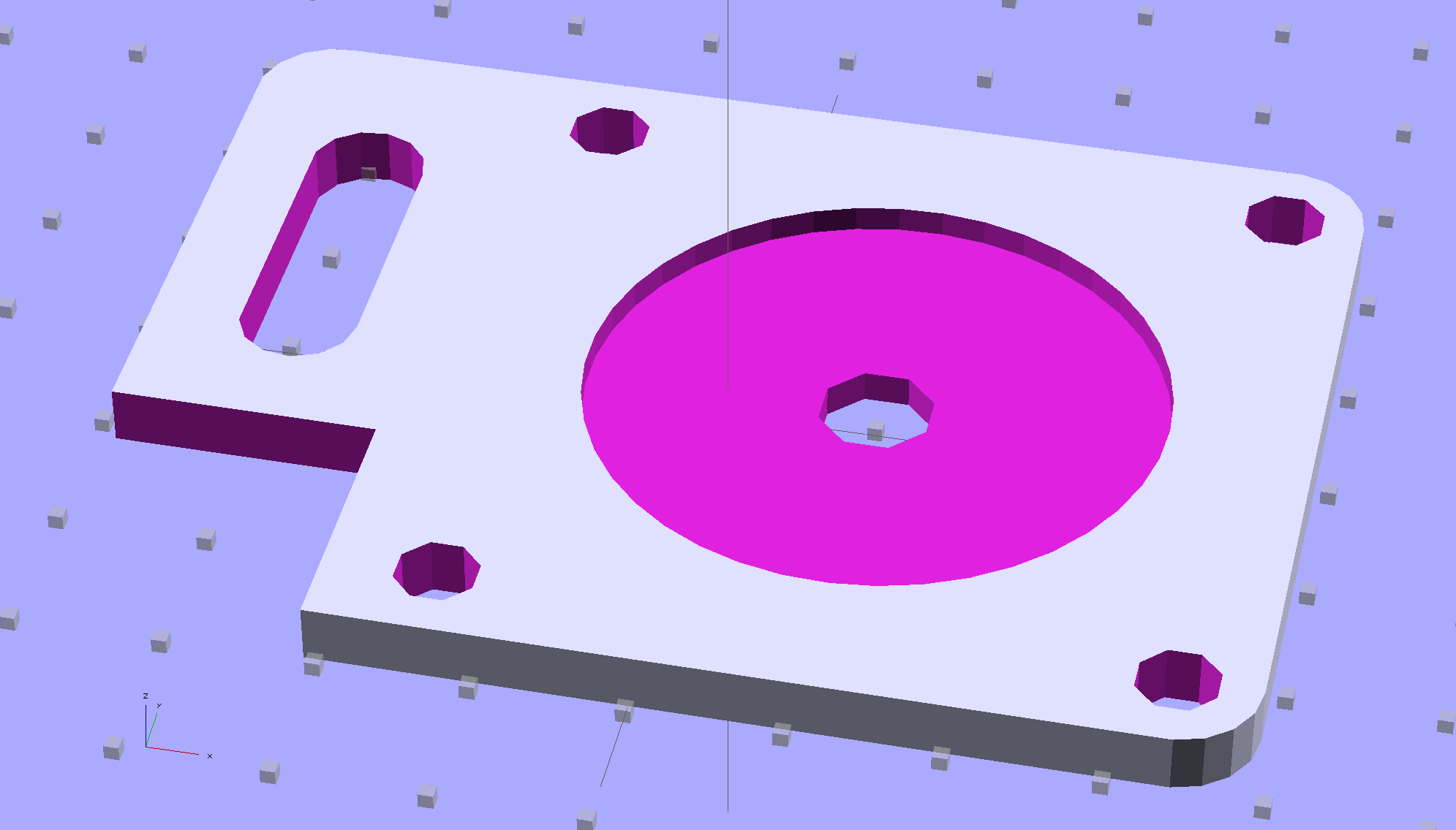
Drive Motor Mount – solid model
And the whole affair fits pretty much like you’d expect:
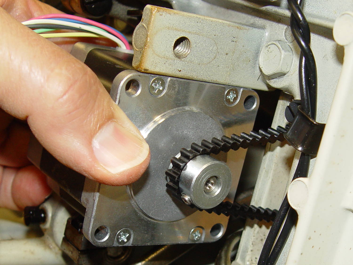
Kenmore 158 – NEMA 23 stepper – on adapter
The NEMA 23 motor doesn’t have the same end profile as the AC motor and the adapter plate gets in the way of the pulley, but flipping the pulley end-for-end perfectly aligned the belt.
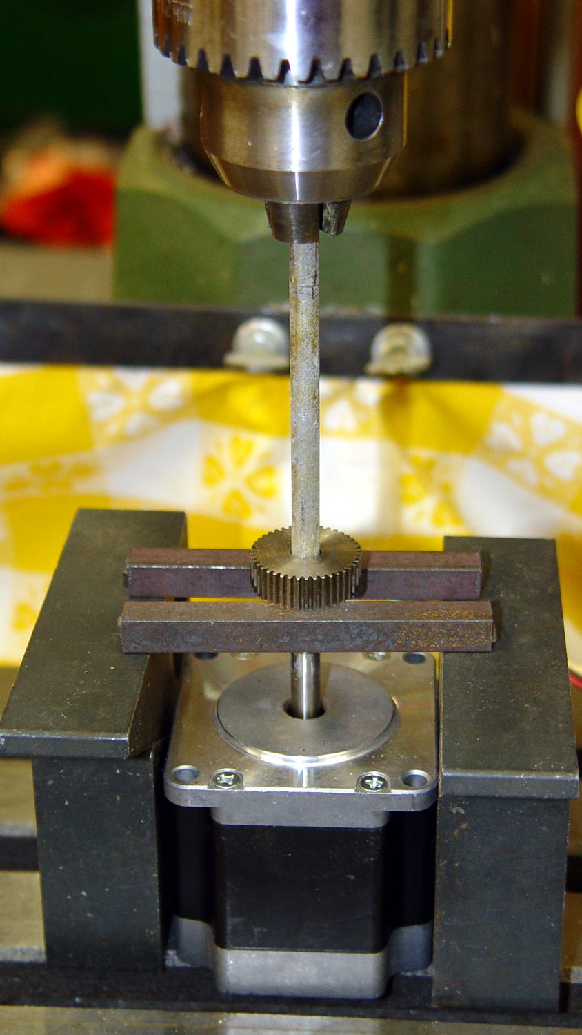
For whatever it’s worth, here’s how I removed the pressed-on gear from the shaft:
NEMA 23 Stepper – removing gear
I’m pretty sure I have a little gear puller somewhere, but it’s not where I expected to find it, which means it could be anywhere.
Much to my astonishment, the shafts on both motors are exactly 1/4″ inch. I filed a flat on the shaft to avoid having the setscrew goober the poor thing.
A stepper isn’t the right hammer for this job, because it can’t possibly reach 8000 rpm, but it’ll be good enough to explore the parameter space and weed out the truly stupid mistakes. A brushless DC motor from halfway around the planet would fit in the same spot.
The OpenSCAD source code:
// NEMA 23 Stepper Mounting Plate
// Ed Nisley - KE4ZNU - June 2014

Layout = "Build";			// Build Show

//- Extrusion parameters must match reality!
//  Print with 4 shells and 3 solid layers

ThreadThick = 0.20;
ThreadWidth = 0.40;

HoleWindage = 0.2;			// extra clearance

Protrusion = 0.1;			// make holes end cleanly

AlignPinOD = 1.70;			// assembly alignment pins: filament dia

inch = 25.4;

function IntegerMultiple(Size,Unit) = Unit * ceil(Size / Unit);

//----------------------
// Dimensions
// Origin at bottom front corner of plate as mounted on machine
//	motor mounted on rear surface, so recess is on that side

PlateThick = 4.0;				// overall plate thickness

SlotOffset = [10.0,13.0,0];		// center nearest origin, motor in X+,Y+ direction
SlotSize = [8.0,25.0];			// diameter of mounting screw , overall end-to-end length

CutoutOffset = [0.0,40.0,0];	// cutout around machine casting
CutoutSize = [18.0,18.0];

MotorBase = 58.0;				// square base plate side
MotorHoleOC = 47.2;				// hole center-to-center spacing
MotorHoleOffset = MotorHoleOC/2;
MotorHoleDia = 5.0;
MotorBaseCornerRadius = (MotorBase - MotorHoleOC)/2;

FlangeWidth = 20.0;				// mounting flange

MotorCenter = [(FlangeWidth + MotorBase/2),(MotorBase/2),0];		// XY of shaft centerline

MotorShaftDia = 7.0;			// allow some clearance

HubDia = 38.5;					// allow some clearance
HubHeight = 1.8;

//----------------------
// Useful routines

module PolyCyl(Dia,Height,ForceSides=0) {			// based on nophead's polyholes

  Sides = (ForceSides != 0) ? ForceSides : (ceil(Dia) + 2);

  FixDia = Dia / cos(180/Sides);

  cylinder(r=(FixDia + HoleWindage)/2,
           h=Height,
           $fn=Sides);
}

module ShowPegGrid(Space = 10.0,Size = 1.0) {

  RangeX = floor(100 / Space);
  RangeY = floor(125 / Space);

	for (x=[-RangeX:RangeX])
	  for (y=[-RangeY:RangeY])
		translate([x*Space,y*Space,Size/2])
		  %cube(Size,center=true);

}

//----------------------
// Build it!

module BasePlate() {

	difference() {
//		cube([(MotorCenter[0] + MotorBase/2),MotorBase,PlateThick],center=false);
		linear_extrude(height = PlateThick) {
			hull() {
				translate([MotorBaseCornerRadius,MotorBaseCornerRadius])
					circle(r=MotorBaseCornerRadius);
				translate([MotorBaseCornerRadius,MotorBase - MotorBaseCornerRadius])
					circle(r=MotorBaseCornerRadius);
				translate([FlangeWidth + MotorBase - MotorBaseCornerRadius,MotorBase - MotorBaseCornerRadius])
					circle(r=MotorBaseCornerRadius);
				translate([FlangeWidth + MotorBase - MotorBaseCornerRadius,MotorBaseCornerRadius])
					circle(r=MotorBaseCornerRadius);
			}
		}

		translate(MotorCenter - [0,0,Protrusion]) {
			rotate(180/8)
				PolyCyl(MotorShaftDia,(PlateThick + 2*Protrusion),8);		// shaft hole
			PolyCyl(HubDia,(HubHeight + Protrusion));						// hub recess
			for (x=[-1,1] , y=[-1,1]) {
				translate([x*MotorHoleOffset,y*MotorHoleOffset,0])
					rotate(180/8)
						PolyCyl(MotorHoleDia,(PlateThick + 2*Protrusion),8);
			}
		}

		translate(SlotOffset - [0,0,Protrusion]) {							// adjustment slot
			linear_extrude(height = (PlateThick + 2*Protrusion))
				hull() {
					circle(d=SlotSize[0]);
					translate([0,(SlotSize[1] - SlotSize[0])])
						circle(d=SlotSize[0]);

				}
		}

		translate(CutoutOffset - [Protrusion,0,Protrusion])
			linear_extrude(height = (PlateThick + 2*Protrusion))
				square(CutoutSize + [Protrusion,Protrusion]);
	}
}

ShowPegGrid();

if (Layout == "Show") {
	BasePlate();
}

if (Layout == "Build") {
	translate([-(SlotOffset[0] + MotorBase/2),MotorBase/2,PlateThick])
		rotate([180,0,0])
			BasePlate();
}
Pinning the top of Mary’s latest quilt used more than 1600 pins: three boxes of specialized quilting safety pins, plus straight quilting pins tucked into all the 3D printed / silicone filled caps. Less than a quarter of the quilt top fits on the table:
Quilt top with pins
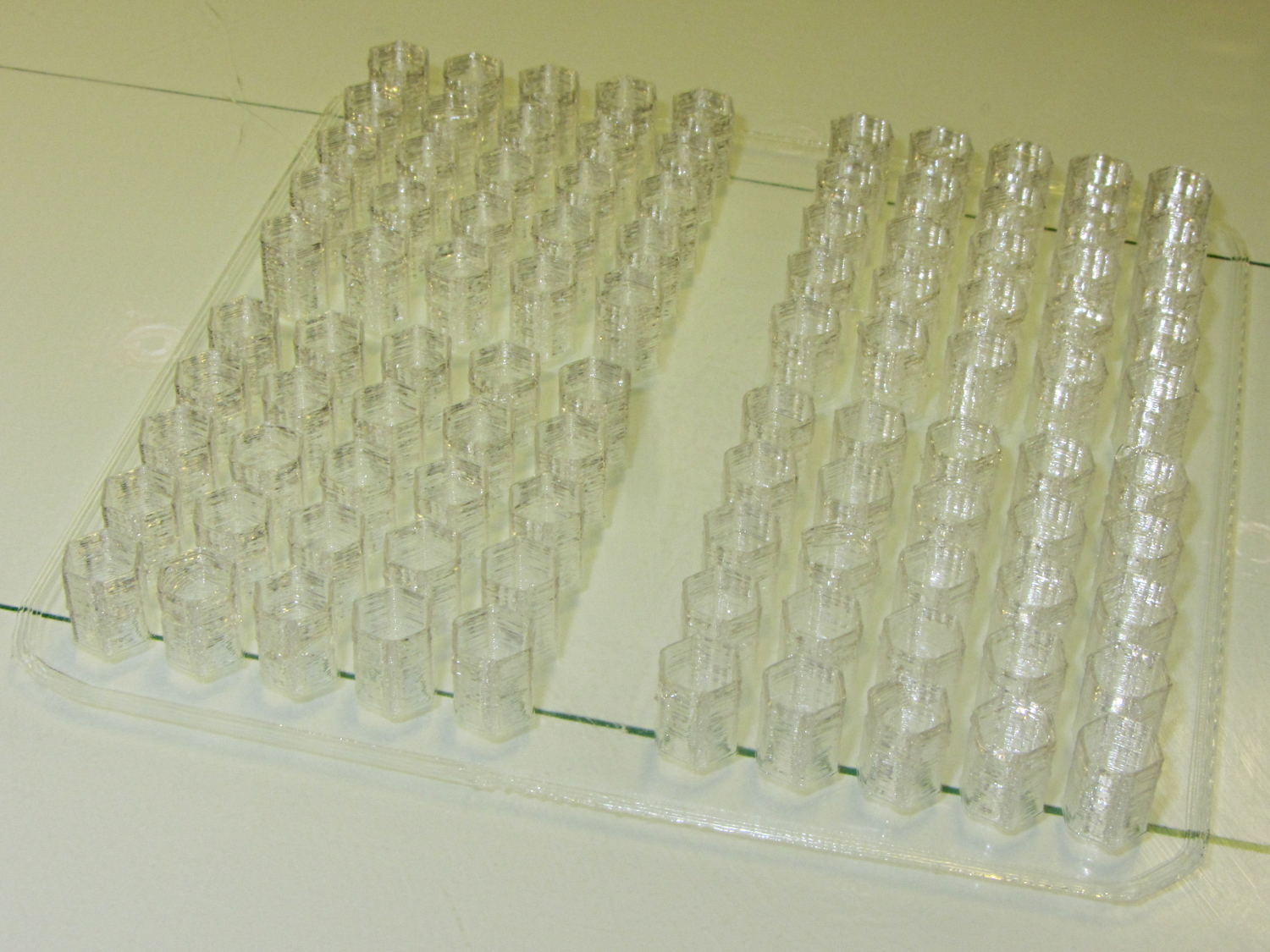
Although Mary doesn’t need them right now, I made another batch of 100 caps for her next project:
Quilting pin caps – 4 x 25 – on platform
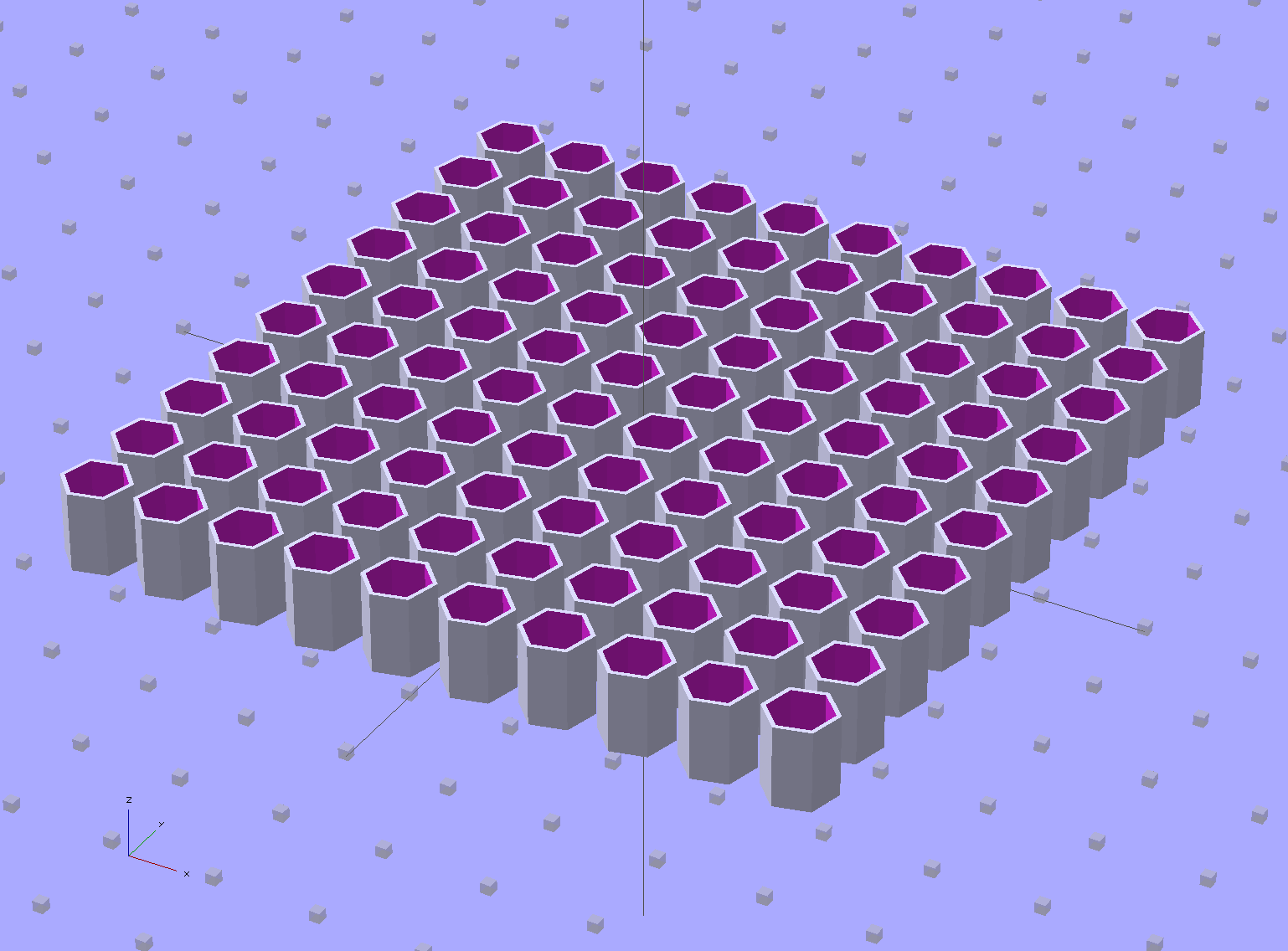
I tweaked the OpenSCAD source to build a 10×10 array:
Quilting Pin Cap – 10×10 array
But it turns out that a 5×5 array of caps, duplicated four times, works out better:
Quilting Pin Cap – 5×5 array
Slic3r takes far longer to process the larger array than to make four copies of the smaller array.
Half an hour later, they’re ready for silicone fill. In retrospect, natural PLA wasn’t a good choice for this job: there’s no way (for me) to take a picture of translucent silicone in crystalline PLA atop waxed paper on a white cutting board under fluorescent light…
On the upside, however, you can see exactly how far the pin goes into the cap:
With the platform and extruder starting at the 19.5 °C = 67 °F Basement Laboratory ambient …
The extruder takes 1 minute to reach 175 °C, overshoots to about 180 °C, crosses 175 °C going downward at 1:30, then gets up to 174 °C again at 3:15. I ran a PID tuning session quite a while ago with inconclusive results. Reducing the initial overshoot would probably increase the time-to-get-ready, with no net improvement.
The platform, which isn’t the stock Makergear hardware, requires 3:30 to reach 69 °C, just under the 70 °C target, at which point it’s ready to start. There’s no insulation under the PCB-trace heater, but some previous tinkering implies that running bare doesn’t make much difference, particularly with a fan blowing on the top surface of the glass.
Remember that’s with an outboard SSR to unload the RAMBo’s MOSFET.
By and large, the M2 is ready to print in under 5 minutes from a standing start, which is just about enough time to spritz hair spray on the platform, load the G-Code into Pronterface, and so forth and so on.
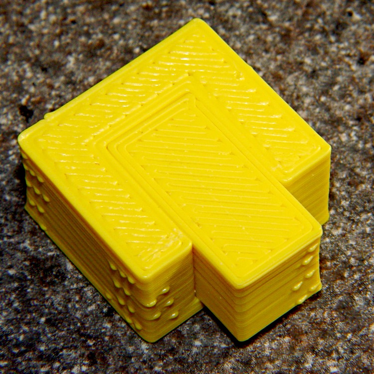
During one of my recent presentations, somebody asked about the accuracy of 3D printed parts, which reminded me of another member of Coasterman’s Essential Calibration Set: the perimeter width/thickness test block. Back in the day, calibrating the extruder meant getting the actual ratio of the thread width to its thickness to match the ideal value you told Skeinforge to use; being a bit off meant that the final dimensions weren’t quite right.
But when I got it right, the Thing-O-Matic printed a test block with considerable success, despite the horrible retraction zittage:
Perimeter Calibration Block – yellow 1.10 rpm 0.33 0.66 mm
Alas, feeding the STL to Slic3r showed that it was grossly non-manifold, and none of the automated repair programs produced good results. Turns out it’s an STL created from a Sketchup model, no surprise there, and the newer slicers seem less tolerant of crappy models.
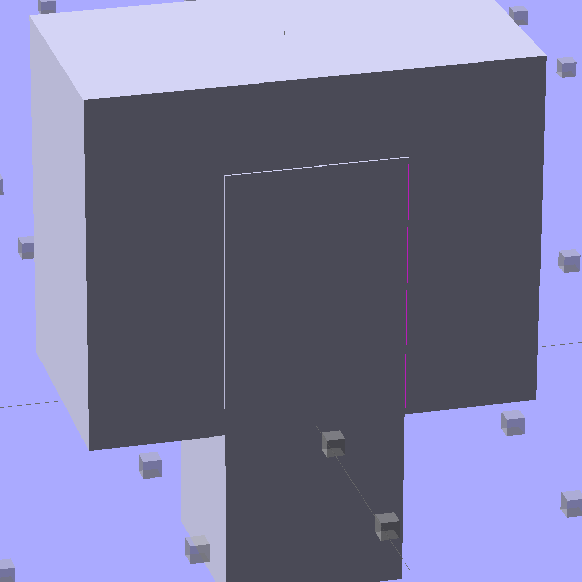
Sooo, here’s a new version built with OpenSCAD:
Fit Test Blocks – build view
You get three blocks-and-plugs at once, arranged in all the useful orientations, so you can test all the fits at the same time. They come off the platform about like you’d expect:
Fit test blocks
I tweaked the code to make the plugs longer than you see there; the short ones were mighty tough to pry out of those slots.
I ran the plugs across a fine file to clean the sides, without removing any base material, and the plugs fit into the slots with a firm push. I’d do exactly the same thing for a CNC milled part from the Sherline, plus breaking the edges & corners.
The plugs doesn’t fit exactly flush in the recesses for the two models on the right side of that first image, because the edges and corners aren’t beveled to match each other. It’s pretty close and, if it had to fit exactly, you could make it work with a few more licks of the file. The left one, printed with the slot on the top surface, fits exactly as flush as the one from the Thing-O-Matic.
Of course, there’s a cheat: the model allows 0.1 mm of internal clearance on all sides of the plug:
Fit Test Block – show view
The outside dimensions of all the blocks and plugs are dead on, within ±0.1 mm of nominal. You’d want to knock off the slight flange at the base and bevel the corners a bit, but unless it must fit inside something else, each object comes off the platform ready to use.
Feel free to dial that clearance up or down to suit your printer’s tolerances.
The OpenSCAD source code:
// Fit test block based on Coasterman's perimeter-wt.stl
//	http://www.thingiverse.com/thing:5573
//	http://www.thingiverse.com/download:17277
// Ed Nisley - KE4ZNU - May 2014

Layout = "Show";

//- Extrusion parameters must match reality!
//  Print with 2 shells and 3 solid layers

ThreadThick = 0.20;
ThreadWidth = 0.40;

Protrusion = 0.1;			// make holes end cleanly

function IntegerMultiple(Size,Unit) = Unit * ceil(Size / Unit);

//----------------------
// Dimensions

Clearance = 0.1;

PlugSize = [10.0,10.0,25.0];
BlockSize = [25.0,13.0,20.0];

PlugOffset = 10.0;

//----------------------
// Useful routines

module ShowPegGrid(Space = 10.0,Size = 1.0) {

  RangeX = floor(100 / Space);
  RangeY = floor(125 / Space);

	for (x=[-RangeX:RangeX])
	  for (y=[-RangeY:RangeY])
		translate([x*Space,y*Space,Size/2])
		  %cube(Size,center=true);

}

module Block() {
	difference() {
		translate([0,0,BlockSize[2]/2])
			cube(BlockSize,center=true);
		translate([0,PlugSize[1] - PlugSize[1]/2 - BlockSize[1]/2,-PlugOffset])
			Plug(Clearance);
	}
}

module Plug(Clear = 0.0) {
	minkowski() {
		translate([0,0,PlugSize[2]/2])
			cube(PlugSize,center=true);
		if (Clear > 0.0)
			cube(Clear,center=true);
	}
}

//----------------------
// Build it

ShowPegGrid();

if (Layout == "Block")
	Block();

if (Layout == "Plug")
	Plug();

if (Layout == "Show") {
	Block();
	translate([0,PlugSize[1] - PlugSize[1]/2 - BlockSize[1]/2,-PlugOffset])
		Plug();
}

if (Layout == "Build") {
	Block();
	translate([0,-15,0])
		Plug();

	translate([-30,0,0]) {
		translate([0,-BlockSize[1]/2,BlockSize[1]/2])
			rotate([-90,0,0])
				Block();
		translate([-PlugSize[2]/2,-15,PlugSize[0]/2])
			rotate([0,90,0])
				Plug();
	}

	translate([30,0,0]) {
		translate([0,0,BlockSize[2]])
			rotate([180,0,180])
				Block();
		translate([-PlugSize[2]/2,-15,PlugSize[1]/2])
			rotate([90,0,90])
				Plug();
	}

}
The Boneheads Raven Skull demo came out reasonably well, albeit in a reduced size, on the Squidwrench Frank-o-Squid:
TOM286 – Raven Skull on platform
So I ran off a full-size version on the M2 for comparison:
Raven Skull – on M2 platform
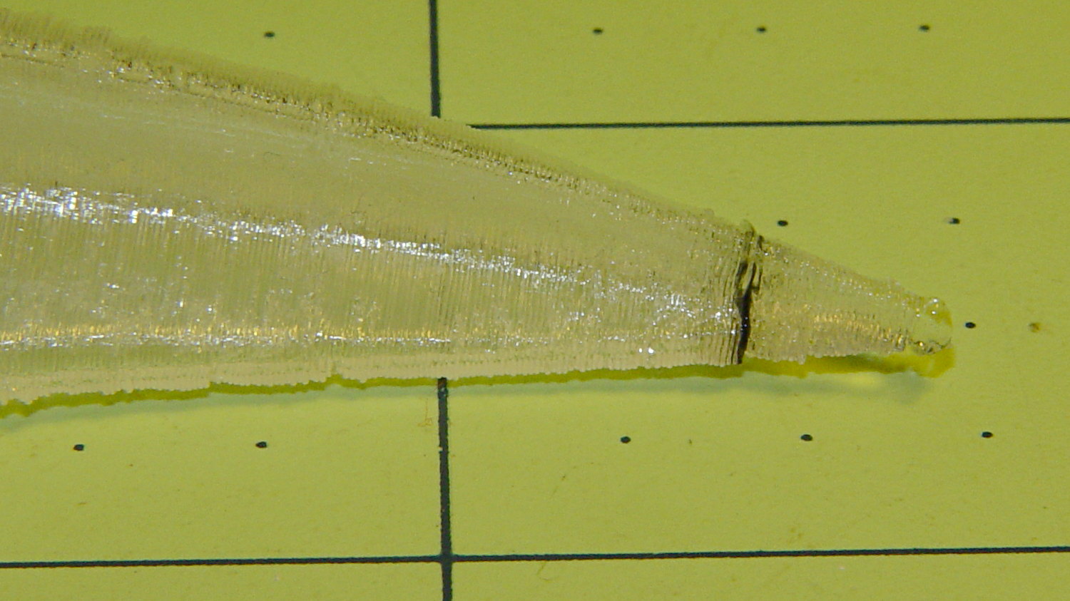
The extruder apparently contained a gobbet of black PLA, left over from the Pink Panther Woman, that managed to hang on inside until the very tip of the beak:
Raven Skull – beak contamination
Close inspection found two black strands closer to the base of the printed parts:
Raven Skull – black contamination
The rear of the skull joins the front just behind the eye sockets, where the solid bottom layers make a visible contrast with the air behind the perimeter threads elsewhere. Refraction darkens some of the threads, but the two black patches stand out clearly.
If it weren’t natural PLA, those flaws wouldn’t be nearly so noticeable.
Were I doing this stuff for a living, I might dedicate a hot end (or an entire extruder) to each color and be done with it.
All in all, the printed quality is about as good as I could expect from a glorified glue gun.
The extreme slowdown while printing the tip of the beak pushed Pronterface’s remaining time estimate over the edge: