The Smell of Molten Projects in the Morning

Ed Nisley's Blog: Shop notes, electronics, firmware, machinery, 3D printing, laser cuttery, and curiosities. Contents: 100% human thinking, 0% AI slop.

Tag: M2

Using and tweaking a Makergear M2 3D printer

  • Tour Easy Running Lights: Same, But Different

    Tour Easy Running Lights: Same, But Different

    Having just finished another set of daytime running lights, we once again have a matched pair of Tour Easy recumbents:

    Tour Easy Running Light - two tail lights
    Tour Easy Running Light – two tail lights

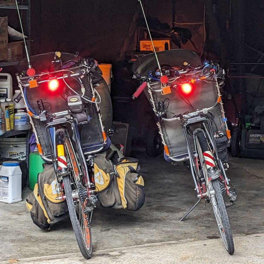
    Although both ‘bents have Bafang 750 W motors with 48 V lithium batteries and both motor controllers have “light” outputs, they are different.

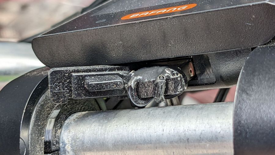
    The controller on Mary’s bike (on the right) has a 6.3 V output that goes active when you press the 500C display’s + button for a few seconds. Those running lights simply use the light output for power, with a bit of tweakage to keep their current draw within the 500 mA limit.

    The controller on my bike (on the left) has a 12 V output that goes active when I press-and-hold the headlight button on the DPC-18 display’s pad. Unlike the 500C, however, the DPC-18 dims its display when the lights are on, rendering it completely illegible in sunlight.

    Because the running lights must operate with the headlight output inactive, a buck converter from a randomly named Amazon seller steps the 48 V battery down to 6.3 V. Note that the usual buck converters have a 36 V upper limit, so you want one with an LM2596HV regulator.

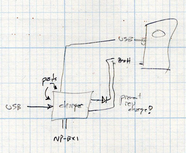
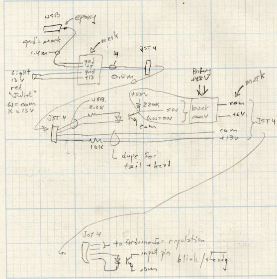
    Because the regulator should be turned off when the motor controller is off, it must have a control input to enable / disable it; even if the regulator has the input pin, most boards don’t bring it out to a pad. The PCB I used has a SW input that must be low to enable the regulator, as shown in the middle doodle amid these scratches:

    Tour Easy running light - buck converter SW control doodles
    Tour Easy running light – buck converter SW control doodles

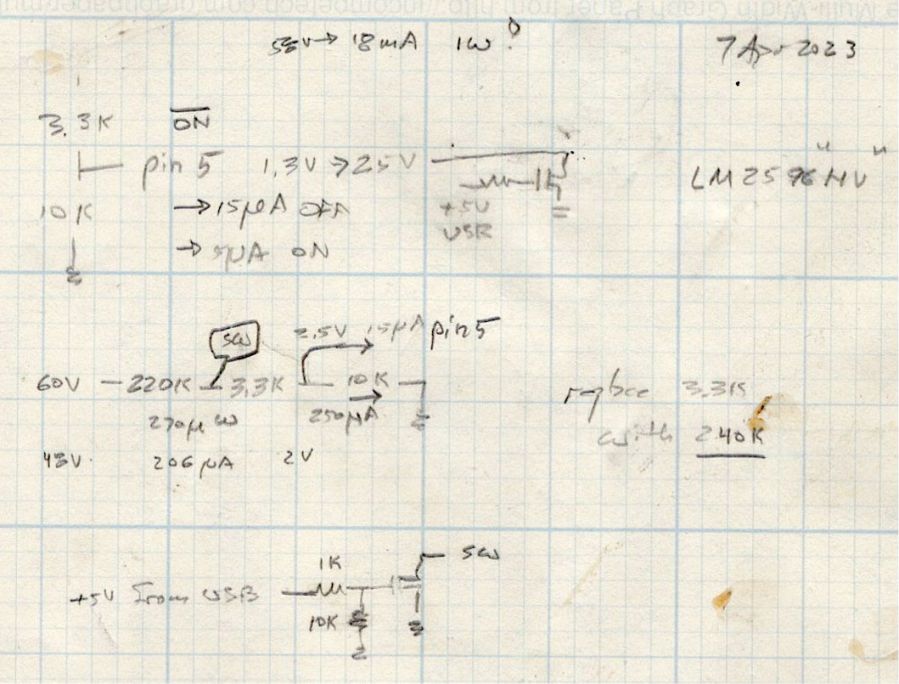
    The SW pad on the PCB drives a voltage divider made from a 3.3 kΩ and a 10 kΩ resistor, with the regulator’s control (pin 5) looking at the junction. Running the numbers suggested a 220 kΩ resistor from the battery + terminal would provide enough current to hold the pin high, while not drawing more than a few hundred microamps, and a transistor could pull it low to turn the regulator on.

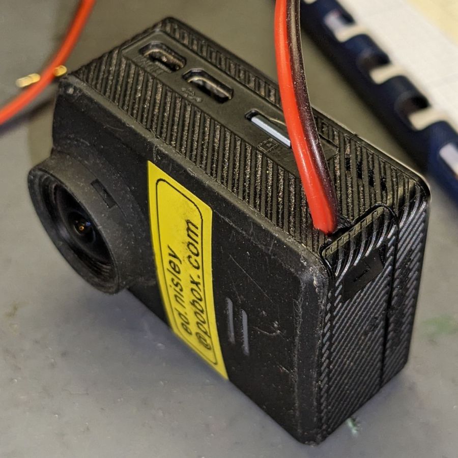
    The DPC-18 display has a USB port to charge your phone on the go, so I hijacked that to get +5 V when the controller is turned on:

    Tour Easy Running Light - Bafang DPC-18 USB plug
    Tour Easy Running Light – Bafang DPC-18 USB plug

    It’s a cut-down USB breakout board with two 24 AWG wires stripped from a ribbon cable soldered in place and coated with epoxy. The silicone port cover sticks out on the left; I eventually jammed it under the display panel in lieu of cutting it off.

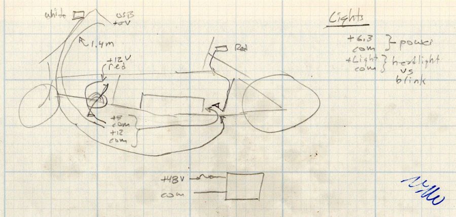
    Although I want the running lights on whenever the controller is on, It Would Be Nice™ to have a steady headlight / taillight in the unlikely event I ever ride after dark. With that in mind, the USB power pair joins another pair from the motor controller’s LIGHT connector (via a red 2-pin Juliet plug), so the firmware can tell when the headlights should be on, and the resulting 4-wire ribbon cable wanders off to the battery mounting plate:

    Tour Easy running light - wire routing doodle
    Tour Easy running light – wire routing doodle

    The connectors along the way are 4-pin JST-SM 2.5 mm, which are most certainly not watertight. We’re fortunate in being able to not ride in the rain whenever we want, so the connectors won’t be exposed to water very often.

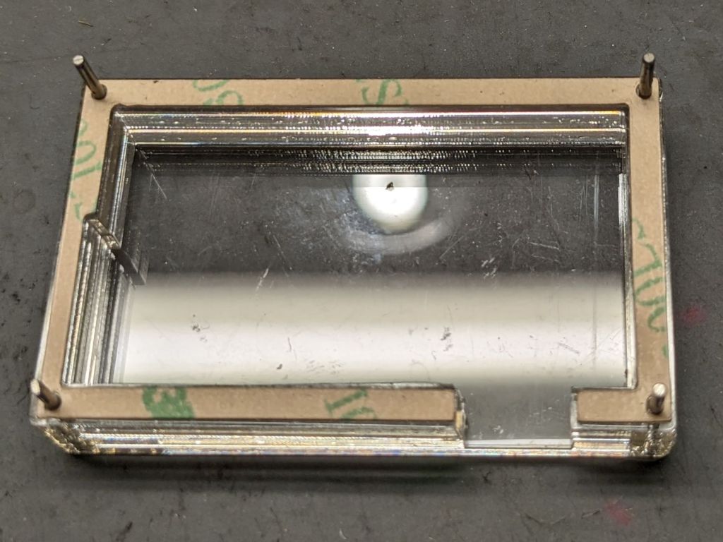
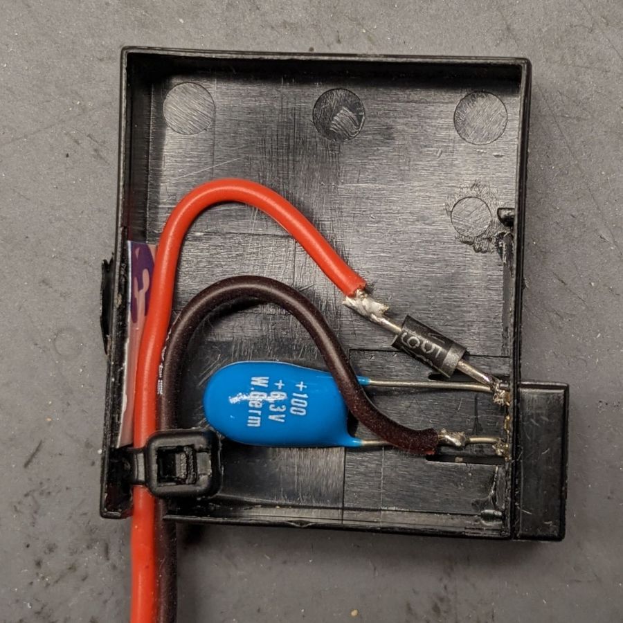
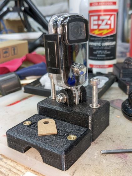
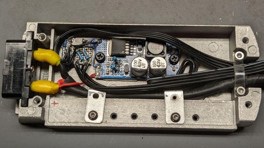
    The battery mounting plate has an aluminum casting with a small compartment, probably intended for a complete e-bike controller, that just barely holds the hardware required to produce the 6.3 V supply:

    Tour Easy Running Light - Bafang battery base circuitry - detail
    Tour Easy Running Light – Bafang battery base circuitry – detail

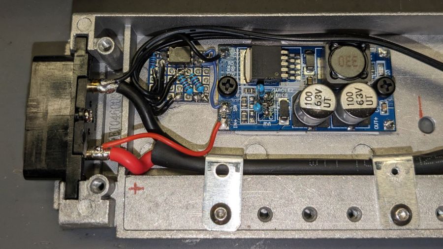
    Yes, those exposed battery terminals with soldered-on wires got a silicone tape wrap. No, there are no fuses involved. The two steel brackets holding the main power cable in place came pre-bent and pre-drilled in a random piece of scrap harvested from some dead equipment; they’re screwed into pre-tapped holes intended for the six TO-220 style power transistors of the missing motor driver.

    The perfboard in the upper left holds an optoisolator for the USB power → SW input and a pair of resistors for the LIGHT signal to the headlight and taillight:

    Tour Easy running light - control doodles
    Tour Easy running light – control doodles

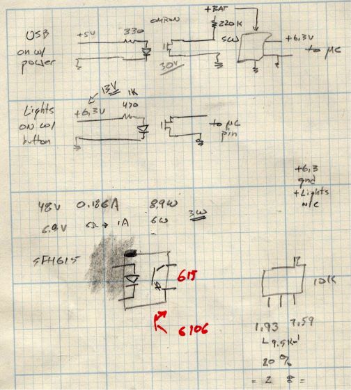
    The optoisolators come from an ancient surplus deal; the bag I thought contained unmarked SFH615 parts apparently got mixed with some unmarked SFH6106 parts with the opposite transistor pinout.

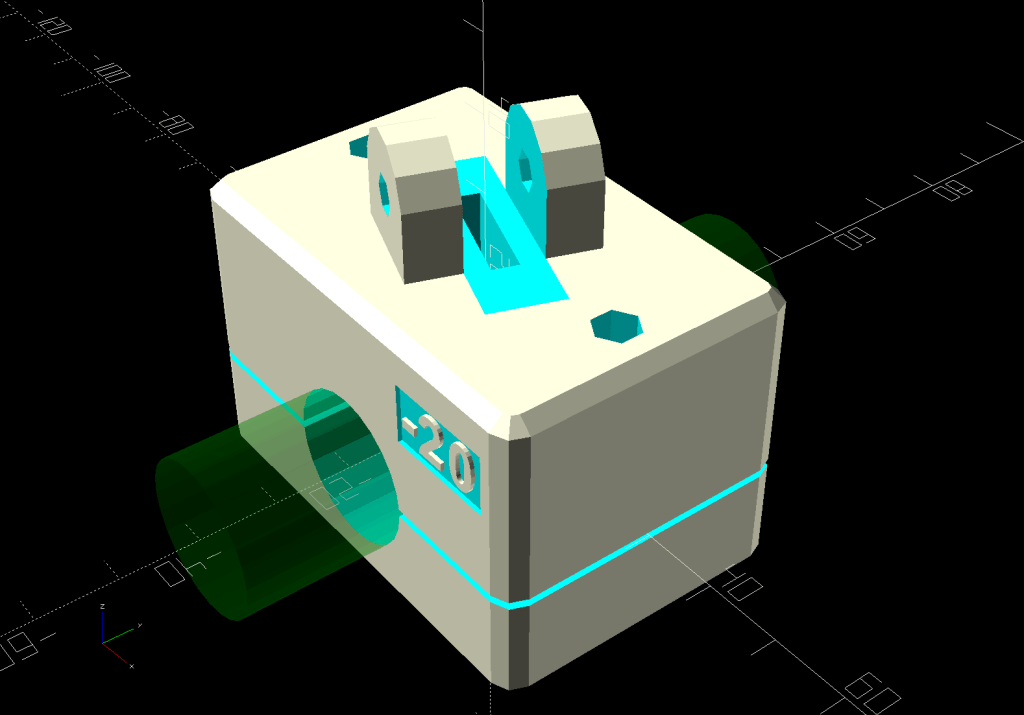
    The sketched trimpot in the lower right was on the buck regulator board, where it stood just an itsy too tall to fit the space available. Given that I would never adjust it, I set it for 6.3 V, removed it, measured the resistances, substituted fixed resistors, and the board should produce 6.3-ish V forevermore.

    The regulator sits atop heatsink tape on a brass sheet with more heatsink tape isolating it from the housing and two nylon screws holding the stack in place.

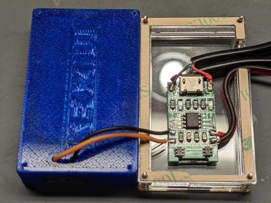
    With the various cables soldered in place:

    Tour Easy Running Light - Bafang battery base circuitry - wired
    Tour Easy Running Light – Bafang battery base circuitry – wired

    The layout of all those cables:

    Tour Easy running light - cable sections doodle
    Tour Easy running light – cable sections doodle

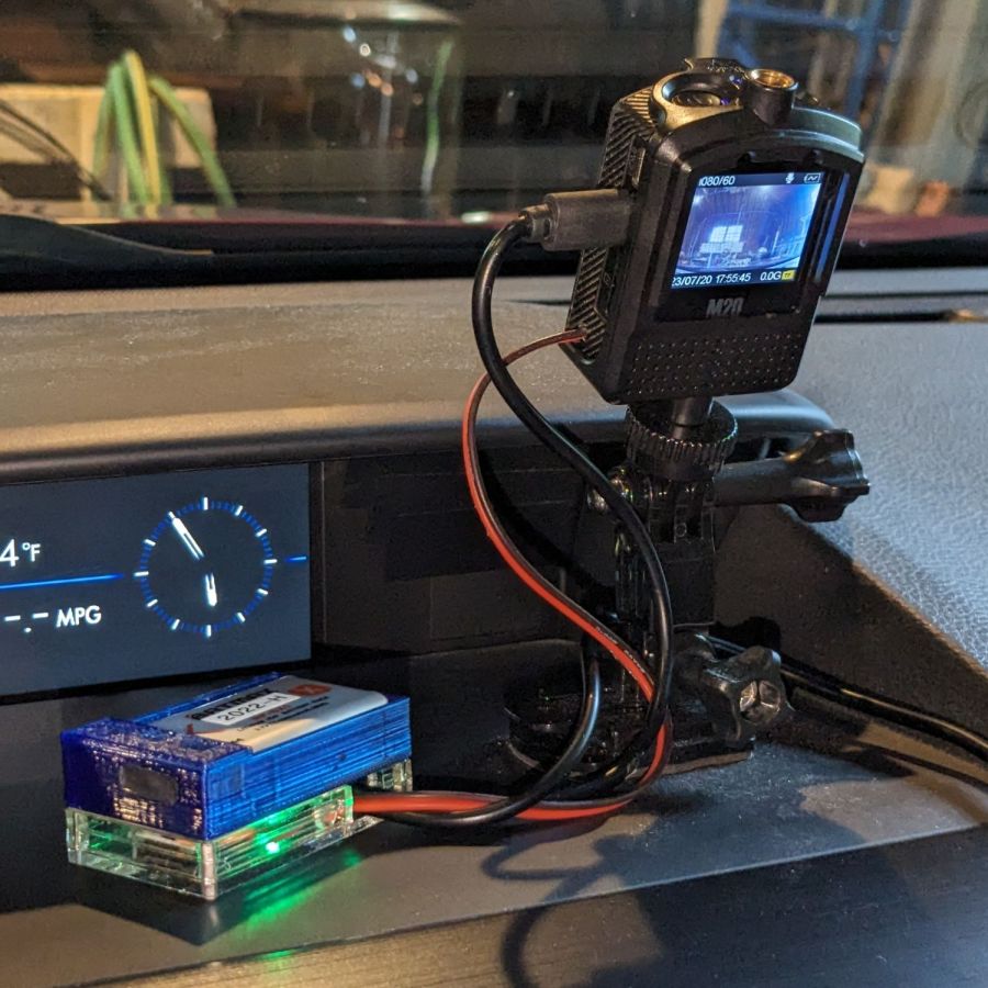
    Surprisingly, It Just Worked™:

    Tour Easy Running Light - installed top view
    Tour Easy Running Light – installed top view

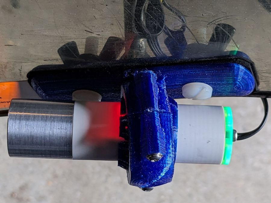
    More details to follow …

  • SJCAM M20 Camera: NP-BX1 Battery and Charger Holder

    SJCAM M20 Camera: NP-BX1 Battery and Charger Holder

    A little tweakage to the NP-BX1 battery holder for the astable multivibrator blinkies produced a simple version with the wire exit holes on the bottom:

    NP-BX1 Simple Holder - solid model
    NP-BX1 Simple Holder – solid model

    The four corner holes hold locating pins in the layered acrylic base:

    SJCAM M20 Battery Replacement - case layers
    SJCAM M20 Battery Replacement – case layers

    Those pins got cut slightly shorter to fit in the battery holder; in this photo they’re serving to align the layers and adhesive sheets while I stacked them up.

    The geometry is straightforward, with the outer perimeter matching the 3D printed battery holder:

    SJCAM M20 Car-Mode Battery Hack - battery case
    SJCAM M20 Car-Mode Battery Hack – battery case

    Cut one base and two wall layers from 3 mm (or a bit less) transparent acrylic, plus three adhesive sheets. I stuck adhesive on both sides of one wall layer, using the pins to align the adhesive, stuck the layer to the base, then topped it with the second wall layer, again using the alignment pins.

    The motivation for transparent layered acrylic is being able to see the charge controller’s red and green status LEDs glowing inside the box. This probably isn’t required, but seemed like a Good Idea™ for the initial version.

    With all that in hand, wire it up:

    SJCAM M20 Battery Replacement - charger wiring
    SJCAM M20 Battery Replacement – charger wiring

    The USB charger PCB sits atop a layer of double-sided foam tape. After verifying that the circuitry worked, I globbed the wires in place with hot-melt glue to make it less rickety than the picture suggests.

    The alert reader will have noticed the holes in the 3D printed NP-BX1 holder were drilled, not printed. In the unlikely event I need another case, the holes will automagically appear in the right place.

    I haven’t yet peeled the protective paper off that top adhesive sheet to make a permanent assembly:

    SJCAM M20 Battery Replacement - trial install
    SJCAM M20 Battery Replacement – trial install

    We use the car so infrequently that it’ll take a while to build up enough confidence to stick it together and stick it to the dashboard.

    On the whole, it’s ugly but sufficient to the task.

    A doodle with key dimensions, plus some ideas not surviving contact with reality:

    SJCAM M20 Car-Mode Battery Hack - case doodle
    SJCAM M20 Car-Mode Battery Hack – case doodle

    I truly hope this entire effort is a waste of time.

  • SJCAM M20 Camera: Car Mode Battery Hack

    SJCAM M20 Camera: Car Mode Battery Hack

    The last lithium cell (a.k.a. battery) for the longsuffering SJCAM M20 transformed itself into a spicy pillow:

    SJCAM M20 - spicy pillow lithium battery
    SJCAM M20 – spicy pillow lithium battery

    SJCAM no longer sells those batteries and nobody else does, either, surely because the +4.35V marking shows they’re a special-formula high-voltage lithium mix that doesn’t work with ordinary chargers. Worse, you can’t substitute an ordinary (i.e. cheap) battery, because applying a high-voltage charger to a 4.2 V cell makes Bad Things™ happen.

    Putting the M20 camera in Car Mode makes it begin recording when it sees 5 V on its USB input and shut down a few seconds after the USB input drops to 0 V. Without the internal battery, the camera’s clock doesn’t survive when the external power vanishes, which seems critical for a camera sitting on a dashboard.

    Mashing all that together, I wondered if I could use one of the many leftover low-voltage NP-BX1 batteries from the Sony AS30V helmet camera without starting a dashboard fire, by preventing the camera from charging the battery, while still using it when the USB input is inactive (which, for our car, is pretty nearly all the time).

    The circuitry, such as it is, uses a cheap 1S USB charge controller and a Schottky diode:

    SJCAM M20 Car-Mode Battery Hack - circuit doodle
    SJCAM M20 Car-Mode Battery Hack – circuit doodle

    Power comes in on the left from a USB converter plugged into the Accessory Power Outlet in the center console and goes out to the camera’s USB jack, using a butchered cable soldered to the charge controller’s pads in the middle. The controller manages the NP-BX1 battery as usual, but a diode prevents the camera from trying to send charge current into the controller.

    This should just barely work, as the diode reduces the battery voltage by a few hundred millivolts, so the camera will see the fully charged low-voltage battery as a mostly discharged high-voltage battery.

    Suiting action to words:

    SJCAM M20 Battery Replacement - circuitry
    SJCAM M20 Battery Replacement – circuitry

    It’s built inside the gutted remains of an M20 battery case. The 100µF tantalum cap provides local buffering to prevent the camera from browning out during bursts of file activity while recording. The wire emerges through holes gnawed in the battery case and the camera housing:

    SJCAM M20 Battery Replacement - camera cable exit
    SJCAM M20 Battery Replacement – camera cable exit

    The charge controller on the other end of the wire lives in a layered laser-cut acrylic case attached to a modified version of the venerable 3D printed NP-BX1 battery holder:

    SJCAM M20 Battery Replacement - charger wiring
    SJCAM M20 Battery Replacement – charger wiring

    More on the cases tomorrow.

    Putting it all together, the lashup goes a little something like this:

    SJCAM M20 Battery Replacement - trial install
    SJCAM M20 Battery Replacement – trial install

    The battery pack will eventually get stuck to the dashboard underneath the overhang, out of direct sunlight. Things get hot in there, but with a bit of luck the battery will survive.

    The rakish tilt puts the hood along the bottom of the image, although raising the camera would reduce tilt and cut down on the skyline view:

    SJCAM M20 Car-Mode Battery Hack - test ride
    SJCAM M20 Car-Mode Battery Hack – test ride

    The battery icon instantly switches from “charging” to “desperately low” when the USB power drops, which is about what I expected, but the camera continues to record for about ten seconds before shutting down normally.

    The NP-BX1 battery in the holder comes from the batch of craptastic BatMax batteries with a depressed starting voltage. An actual new cell with a slightly higher voltage would keep the camera slightly happier during those last ten seconds, but … so far, so good.

    Another possibility would be a trio of 1.5 V bucked lithium AA cells, with the diode to prevent charging and minus the charger.

  • Patio Chair Foot Adapters

    Patio Chair Foot Adapters

    Some years ago we acquired a free quartet of aluminum-frame patio chairs in need of new straps and feet. Eventually enough straps broke to force me to re-strap the things and I finally got around to replacing the badly worn OEM feet:

    Patio Chair Foot Adapter - OEM feet
    Patio Chair Foot Adapter – OEM feet

    The small drilled holes let me yoink most them out with sheet-metal screw attached to a slide hammer, then apply the Designated Prydriver to the most recalcitrant / broken ones.

    Some feet had worn enough to expose the aluminum tubes, but most had at least a thin layer of plastic:

    Patio Chair Foot Adapter - OEM foot erosion
    Patio Chair Foot Adapter – OEM foot erosion

    Obviously, I should have stripped and repainted the frames (if that’s possible, as they’re probably powder-coated), but a man’s gotta know his limitations and this job needed to get done.

    One might think patio furniture replacement feet are cheap & readily available, but no amount of keyword engineering produced search results with any degree of assured fit, so I conjured adapters for screw-in feet from the vasty digital deep:

    Patio Chair Foot Adapters - solid models
    Patio Chair Foot Adapters – solid models

    This was a long-awaited opportunity to explore the BOSL2 library and it worked wonderfully well. Each adapter is whittled from a huge hex nut with threads that perfectly fit the M8×1.25 stud, which stands vertically through the middle of the (slightly oval) bottom surface parallel to the floor.

    The front tubes have a 5° angle with respect to the vertical:

    Patio Chair Foot Adapter - front
    Patio Chair Foot Adapter – front

    And the rear tubes are 15° off:

    Patio Chair Foot Adapter - rear
    Patio Chair Foot Adapter – rear

    Each adapter has an orientation notch pointing toward the front of the front leg and the rear of the rear leg:

    Patio Chair Foot Adapter - orientation notch
    Patio Chair Foot Adapter – orientation notch

    I expected to apply adhesive on the inside and outside of the adapters, but they tapped firmly into place inside the legs and the studs screwed firmly into them, so we’ll see how they survive in actual use. I expect the studs to rust after a while, but that might not be the most awful thing ever to happen.

    The OpenSCAD source code as a GitHub Gist:

    // Patio chair foot adapter
    // Ed Nisley – KE4ZNU – 2023-06
    include <BOSL2/std.scad>
    include <BOSL2/threading.scad>
    LegAngles = [5,15];
    /* [Hidden] */
    ThreadThick = 0.25;
    ThreadWidth = 0.40;
    HoleWindage = 0.2;
    Protrusion = 0.1; // make holes end cleanly
    function IntegerMultiple(Size,Unit) = Unit * ceil(Size / Unit);
    ID = 0;
    OD = 1;
    LENGTH = 2;
    inch = 25.4;
    //———————-
    // Dimensions
    LegTube = [18.8 – HoleWindage,22.5,0];
    Stud = [8.0,1.25,10.0]; // M8x1.25 foot stud
    FlangeBase = 3.0;
    //———————–
    for (i=[0:len(LegAngles)-1]) {
    ang = LegAngles[i];
    FlangeIncr = LegTube[OD]*tan(ang);
    Flange = [Stud[0],LegTube[OD],FlangeBase + FlangeIncr];
    translate([i*1.5*Flange[OD],0,0])
    difference() {
    translate([0,0,0*-FlangeIncr/2])
    threaded_nut(2*Flange[OD],Stud[0],1.5*Stud[2],Stud[1],
    anchor=BOTTOM,bevel=false,$slop=0.2);
    rotate([0,ang,0]) {
    translate([0,0,FlangeBase + FlangeIncr/2])
    tube(4*Stud[2],2*Flange[OD],LegTube[ID]/2,
    anchor=BOTTOM);
    tube(4*Stud[2],2*Flange[OD],Flange[OD]/2,
    anchor=CENTER);
    }
    cube([Flange[OD],ThreadWidth,2*ThreadThick],anchor=BOTTOM+RIGHT);
    }
    }
  • Tour Easy: Another SJCAM C100+ Mount

    Tour Easy: Another SJCAM C100+ Mount

    Eight years of progress in the action camera world gets you from a rather expensive Cycliq Fly6:

    Tour Easy - Fly6 image
    Tour Easy – Fly6 image

    To an SJCAM C100+ camera costing the better part of fifty bucks on closeout:

    Tour Easy - C100 image
    Tour Easy – C100 image

    The camera is mounted on the side of the seat frame on Mary’s Tour Easy:

    Tour Easy C100 mount - side rail
    Tour Easy C100 mount – side rail

    The slightly tilted picture comes from the frame rail’s incline. My C100+ camera mounts on the horizontal part of the rail:

    Tour Easy C100 mount - rear rail
    Tour Easy C100 mount – rear rail

    As expected, the internal battery does not last for our usual hour-long rides, so the cameras now operate in “car mode”: recording starts when we plug in the USB battery pack and stops shortly after unplugging.

    I started with the waterproof case on my bike:

    Tour Easy - SJCAM C100 mount - installed
    Tour Easy – SJCAM C100 mount – installed

    Which (obviously) does not allow for an external battery, so they’re now in the “frame” mount. The hatch covering the MicroSD card and USB Micro-B connector (and a Reset button!) is on the bottom of the camera, but (fortunately) the whole affair mounts up-side-down and the settings include an image flip mode.

    Putting the camera on the side required changing the mount angle from -20° to +35°:

    SJCAM C100 Mount - 35 degree solid model
    SJCAM C100 Mount – 35 degree solid model

    The ergonomics / user interface of this whole setup is terrible:

    • The camera’s flexible hatch is recessed inside the frame far enough that it cannot be opened without using a small & sharp screwdriver
    • The USB jack is slightly off-center, so lining the plug up with the camera body doesn’t align it with the jack
    • The MicroSD card is in a push-to-release socket, but its raised ridge faces the hatch flap and cannot be reached by a fingernail. I added a small tab that helps, but it’s difficult to grasp.

    Extracting the video files from the camera through the app is an exercise in frustration. Having already figured out how to do this for the other cameras in the fleet, it’s easier to fumble with the MicroSD card.

    I devoutly hope we never really need any of the videos.

  • Bafang vs. Tour Easy: Chain Guide

    Bafang vs. Tour Easy: Chain Guide

    After adding the Bafang motor to my Tour Easy, the chain has fallen off the chainring a few times, prompting the gap filler between the motor and the chainring spider. That this has never happened to Mary’s essentially identical Tour Easy suggests I have a different shift technique, but adding a chain catcher seemed easier than re-learning shifting:

    Chain Catcher - top view
    Chain Catcher – top view

    It’s more properly called a “chain guide” and is basically a shifter cage minus the mechanism:

    Chain Catcher - side view
    Chain Catcher – side view

    Because the Tour Easy frame has a 25 mm tube where the guide’s clamp expects a minimum 31.8 mm tube, a 3D printed adapter fills the gap:

    Chain Catcher adapter ring - solid model
    Chain Catcher adapter ring – solid model

    The hole is off-center because it seemed like a good idea, although it’s not strictly necessary. The flange helps align the pieces while tightening the clamp screw.

    The guide cage clears the chain on all sides while up on the work stand, but there’s nothing like getting out on the road to find out why something doesn’t work as you expect.

    The OpenSCAD source code as a GitHub Gist:

    // Chain catcher adapter ring
    // Ed Nisley – KE4ZNU – 2023-05
    /* [Hidden] */
    ThreadThick = 0.25;
    ThreadWidth = 0.40;
    HoleWindage = 0.2;
    Protrusion = 0.1; // make holes end cleanly
    function IntegerMultiple(Size,Unit) = Unit * ceil(Size / Unit);
    ID = 0;
    OD = 1;
    LENGTH = 2;
    inch = 25.4;
    //———————-
    // Dimensions
    TubeOD = 26.0; // frame tube with silicone tape
    Clamp = [35.0,39.0,12.0]; // Chain catcher clamp ring
    Flange = [Clamp[ID],Clamp[OD],3*ThreadThick];
    Kerf = 1.0;
    Offset = (Clamp[ID] – TubeOD)/2 – 3*ThreadWidth;
    NumSides = 2*3*4;
    //———————–
    $fn=NumSides;
    difference() {
    union() {
    cylinder(d=Flange[OD],h=Flange[LENGTH]);
    cylinder(d=Clamp[ID],h=Clamp[LENGTH]+Flange[LENGTH]);
    }
    cube([2*Flange[OD],Kerf,3*Clamp[LENGTH]],center=true);
    translate([0,Offset,0])
    cylinder(d=TubeOD,h=3*Clamp[LENGTH],center=true);
    }
  • Tour Easy: SJCAM C100+ Mount

    Tour Easy: SJCAM C100+ Mount

    The batteries (which are no longer available) and the control buttons have worn out on the SJCAM M20 camera on the back of my Tour Easy, so a replacement is in order:

    Tour Easy - SJCAM C100 mount - installed
    Tour Easy – SJCAM C100 mount – installed

    It’s an SJCAM C100+ in its waterproof housing, screwed to a block descended from the M20 mount:

    SJCAM C100 Mount - solid model
    SJCAM C100 Mount – solid model

    The C100+ has a non-replaceable lithium pouch battery that may not last for the hour or so we generally ride, but at least this is a starting point for seeing how the thing works.

    The PrusaSlicer preview shows the support structure inside the seat rail arches:

    SJCAM C100 Mount - slicer
    SJCAM C100 Mount – slicer

    That appears under the four central facets of each arch, where I “painted” the support enforcers, because the automagic supports fill the entire arch and are basically impossible to pry off.

    The hole between the ears on the top holds an aluminum tab intended to diffuse the wobble from that tall camera. A laser-cut chipboard template simplified drilling & cutting the tab from an aluminum sheet:

    Tour Easy - SJCAM C100 mount - test fit
    Tour Easy – SJCAM C100 mount – test fit

    The tab and the brass inserts are held in place with JB Weld Plastic Bonder, my new go-to adhesive for such things.

    The camera includes WiFi and the inevitable app lets you download images without opening the case. Because I’ll be charging the camera after each ride, I may as well just haul the whole thing inside, plug it into a USB port, and proceed as before.

    For future reference, the manual details the operating modes:

    SJCAM C100 Manual - Modes
    SJCAM C100 Manual – Modes

    Because the camera powers up with WiFi enabled and I have no plans to communicate with it while riding, the startup sequence will be:

    • Long-press to power on
    • Double-click to disable WiFi
    • Single-click to start recording

    The OpenSCAD source code as a GitHub Gist:

    // SJCAM C100+ Camera Mount for Tour Easy seat back rail
    // Ed Nisley – KE4ZNU
    // 2023-04
    /* [Layout Options] */
    LookAngle = -20; // camera angle, looking backwards = 0°
    Layout = "Show"; // [Show,Build]
    /* [Hidden] */
    ThreadWidth = 0.40;
    ThreadThick = 0.25;
    HoleWindage = 0.2;
    Protrusion = 0.1;
    ID = 0;
    OD = 1;
    LENGTH = 2;
    //—–
    // Dimensions
    ClampScrew = [5.0,10.0,40.0]; // ID=thread OD=washer LENGTH=total
    ClampInsert = [5.0,7.5,10.5]; // brass insert
    MountScrew = [5.0,10.0,23.0]; // ID=thread OD=washer LENGTH=under nut
    MountInsert = [5.0,7.5,10.5]; // ID=screw OD, OD=knurl dia
    EmbossDepth = 2*ThreadThick + Protrusion; // recess depth + Protrusion beyond surface
    DebossHeight = EmbossDepth; // text height + Protrusion into part
    RailOD = 20.0; // slightly elliptical in bent section
    RailSides = 2*3*4;
    ClampOA = [60.0,40.0,ClampScrew[LENGTH]]; // set clamp size to avoid weird screw spacing
    echo(ClampOA = ClampOA);
    ClampScrewOC = IntegerMultiple(ClampOA.x – ClampScrew[OD] – 10*ThreadWidth,1.0);
    echo(ClampScrewOC = ClampScrewOC);
    ClampOffset = 5.0; // in case we need more room on top
    ClampRadius = 3.0;
    ClampSides = 8;
    Kerf = 1.0; // slice through the middle
    // center mount blade, Z = depth into block
    MountBlade = [15.0 + 2*HoleWindage,
    3.0 + 2*HoleWindage,
    (ClampOA.z – RailOD + ClampOffset)/2 – 4*ThreadThick + Protrusion];
    echo(MountBlade = MountBlade);
    MountRadius = MountBlade.x / 2;
    MountGap = 9.5; // camera mount gap around center blade
    MountOffset = [0,0,7.0]; // mount hole offset from block surface
    FadeColor = "Green";
    FadeAlpha = 0.25;
    //—–
    // Useful routines
    function IntegerMultiple(Size,Unit) = Unit * ceil(Size / Unit);
    module PolyCyl(Dia,Height,ForceSides=0) { // based on nophead's polyholes
    Sides = (ForceSides != 0) ? ForceSides : (ceil(Dia) + 2);
    FixDia = Dia / cos(180/Sides);
    cylinder(r=(FixDia + HoleWindage)/2,
    h=Height,
    $fn=Sides);
    }
    //—–
    // Clamp
    // Grips seat frame rail
    // Origin at middle of seat rail, X rearward, Y parallel to seat frame rail
    // Block offset raises whole thing
    module Clamp() {
    difference() {
    translate([0,0,ClampOffset]) {
    difference() {
    union() {
    hull() // the main block
    for (i=[-1,1], j=[-1,1], k=[-1,1])
    translate([i*(ClampOA.x – 2*ClampRadius)/2,
    j*(ClampOA.y – 2*ClampRadius)/2,
    k*(ClampOA.z – 2*ClampRadius)/2])
    sphere(r=ClampRadius/cos(180/ClampSides),$fn=ClampSides);
    hull() // camera mount boss
    for (k=[0,1])
    translate([0,0,k*(MountOffset.z) + ClampOA.z/2])
    rotate([0,90,LookAngle + 90]) rotate(180/12)
    cylinder(r=MountRadius,h=MountScrew[LENGTH],center=true,$fn=12);
    }
    for (i=[-1,1]) // clamp inserts
    translate([i*ClampScrewOC/2,0,-(ClampOA.z/2 + Protrusion)])
    rotate(180/6)
    PolyCyl(ClampInsert[OD],ClampInsert[LENGTH],6);
    for (i=[-1,1]) // clamp screw holes
    translate([i*ClampScrewOC/2,0,-ClampOA.z])
    rotate(180/6)
    PolyCyl(ClampScrew[ID],2*ClampOA.z,6);
    translate([0,0,ClampOA.z/2 – (MountBlade.z/2 – Protrusion/2)]) // camera center blade
    rotate(LookAngle)
    cube(MountBlade,center=true);
    rotate(LookAngle + 90) // camera mount boss slot
    translate([0,0,ClampOA.z/2 + 2*MountRadius])
    cube([MountGap,4*MountRadius,4*MountRadius],center=true);
    translate([0,0,ClampOA.z/2 + MountOffset.z]) // camera mount boss hole
    rotate([90,0,LookAngle])
    cylinder(d=MountScrew[ID],h=4*MountGap,center=true,$fn=6);
    translate([0.3*ClampOA.x, // recess for LookAngle legend
    -(ClampOA.y/2 – (EmbossDepth – Protrusion)/2),
    ClampOA.z/4])
    cube([15,EmbossDepth,8],center=true);
    translate([0,0,-ClampOA.z/2 + (EmbossDepth – Protrusion)/2]) // recess for ID legend
    cube([35,10,EmbossDepth],center=true);
    }
    translate([0.3*ClampOA.x, // LookAngle legend
    -ClampOA.y/2 + DebossHeight + Protrusion/2,
    ClampOA.z/4])
    rotate([90,0,00])
    linear_extrude(height=DebossHeight,convexity=20)
    text(text=str(LookAngle),size=6,spacing=1.20,
    font="Arial:style:Bold",halign="center",valign="center");
    translate([0,0,-ClampOA.z/2]) // ID legend
    linear_extrude(height=DebossHeight,convexity=20)
    mirror([0,1,0])
    text(text="KE4ZNU",size=5,spacing=1.20,
    font="Arial:style:Bold",halign="center",valign="center");
    }
    cube([2*ClampOA.x,2*ClampOA.y,Kerf],center=true); // split across rail
    rotate([90,0,0]) // seat rail
    cylinder(d=RailOD,h=2*ClampOA.y,$fn=RailSides,center=true);
    }
    }
    //—–
    // Build things
    // Layouts for design & tweaking
    if (Layout == "Show") {
    Clamp();
    color(FadeColor,FadeAlpha)
    rotate([90,0,0])
    cylinder(d=RailOD,h=2*ClampOA.y,$fn=RailSides,center=true);
    }
    // Build layout
    if (Layout == "Build") {
    translate([0,0.7*ClampOA.y,0])
    difference() {
    translate([0,0,-Kerf/2])
    Clamp();
    translate([0,0,-ClampOA.z])
    cube(2*ClampOA,center=true);
    }
    translate([0,-0.7*ClampOA.y,-0])
    difference() {
    translate([0,0,-Kerf/2])
    rotate([0,180,0])
    Clamp();
    translate([0,0,-ClampOA.z])
    cube(2*ClampOA,center=true);
    }
    }