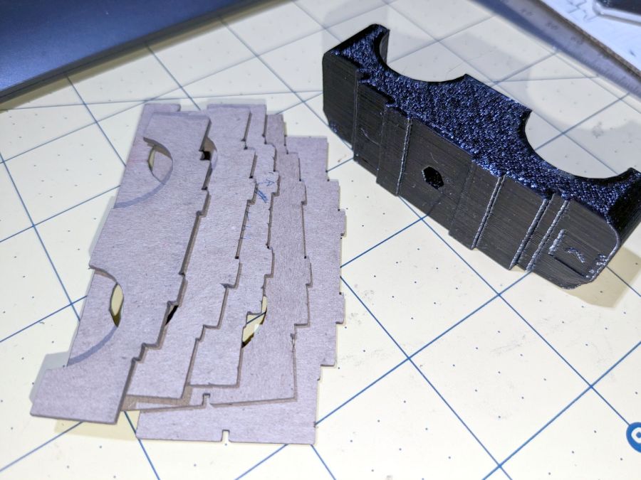
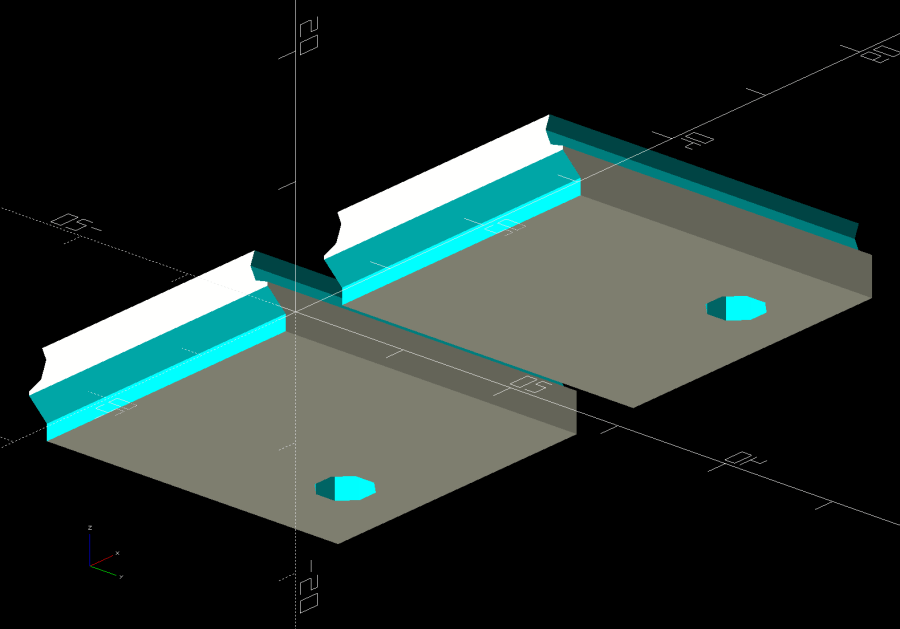
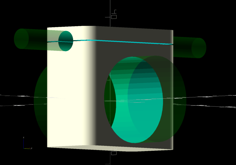
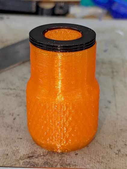
The mounting block under the electronics box for the new UPP battery has a recess for an M5 tee nut:

As with the Terry frame mounts, I glued the modified tee nut in place with JB Plastic Bonder urethane adhesive, did a test fit on the bike, discovered the whole affair had to sit about 10 mm forward, put the new frame measurement into the OpenSCAD code, and ran off a new block.
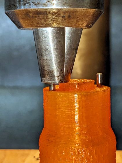
Which gave me the opportunity to perch the old block atop the bench vise with the tee nut aimed downward between the open jaws, run an M5 bolt into the nut, and give it a good thwack with a hammer:

Although the urethane adhesive didn’t bond uniformly across the tee nut, it had enough grip to tear the PETG layers apart and pull chunks out of the block.
As with the tee nuts on the Terry bike, this one will be loaded to pull into the block, so it will never endure any force tending to pull things apart, but it’s nice to know how well JB Plastic Bonder works.
I chiseled the PETG and adhesive debris off the tee nut, cleaned it up, slathered more Bonder on the new block, and squished the nut in place. After I get the electronics box sorted out, the whole affair will never come apart again!