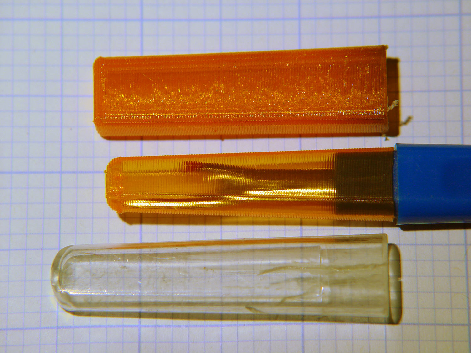
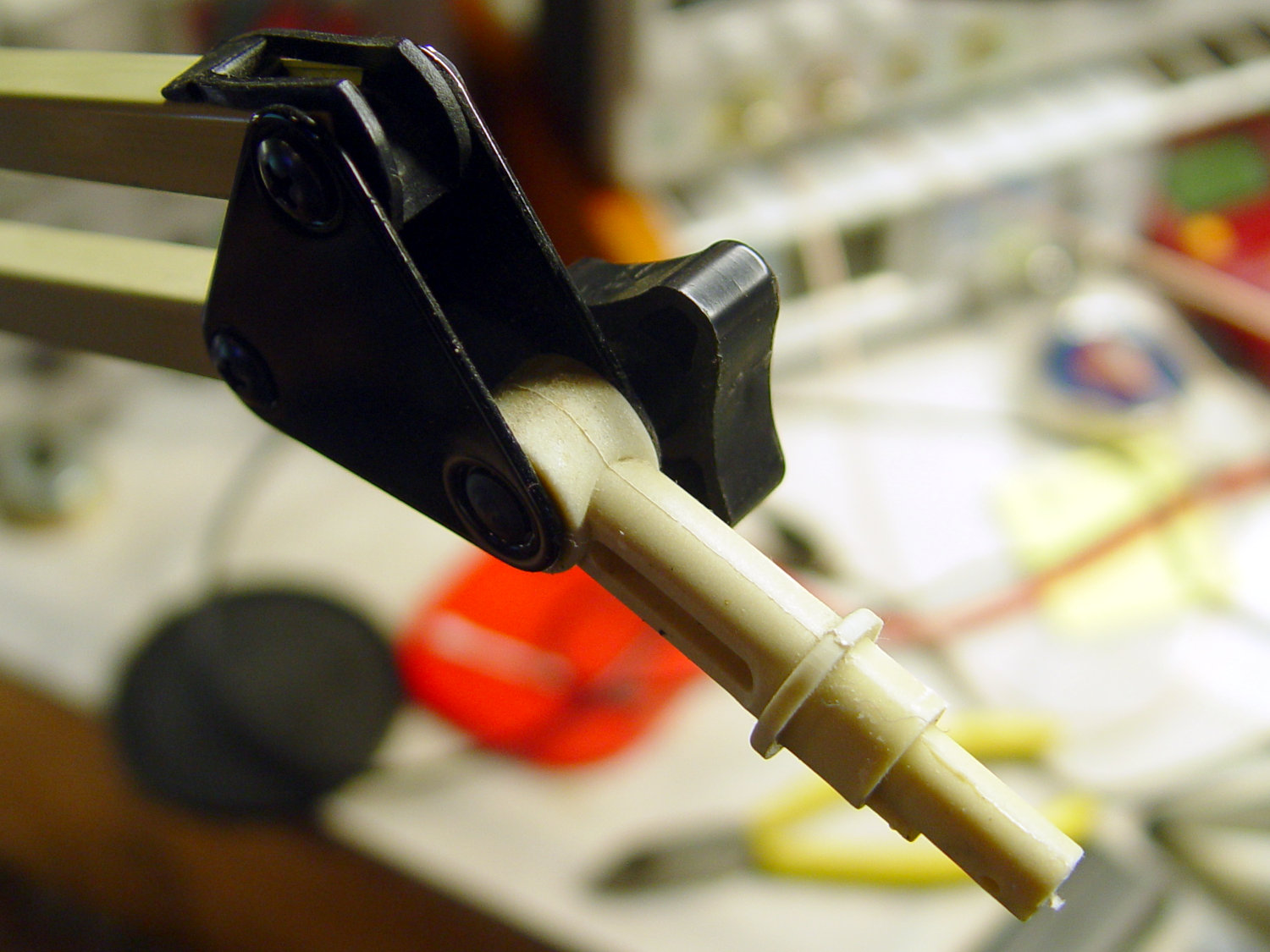
The anodized body of the drag knife on the left measures exactly 12.0 mm OD:
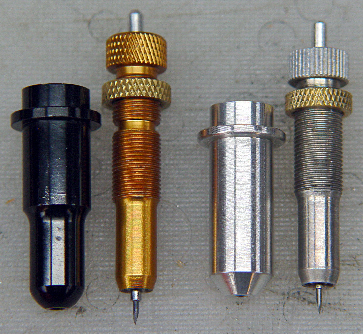
Which happy fact suggested I might be able to use a standard LM12UU linear bearing, despite the obvious stupidity of running an aluminum “shaft” in a steel-ball bearing race:

The 12 mm section extends about halfway through the bearing, with barely 3 mm extending out the far end:
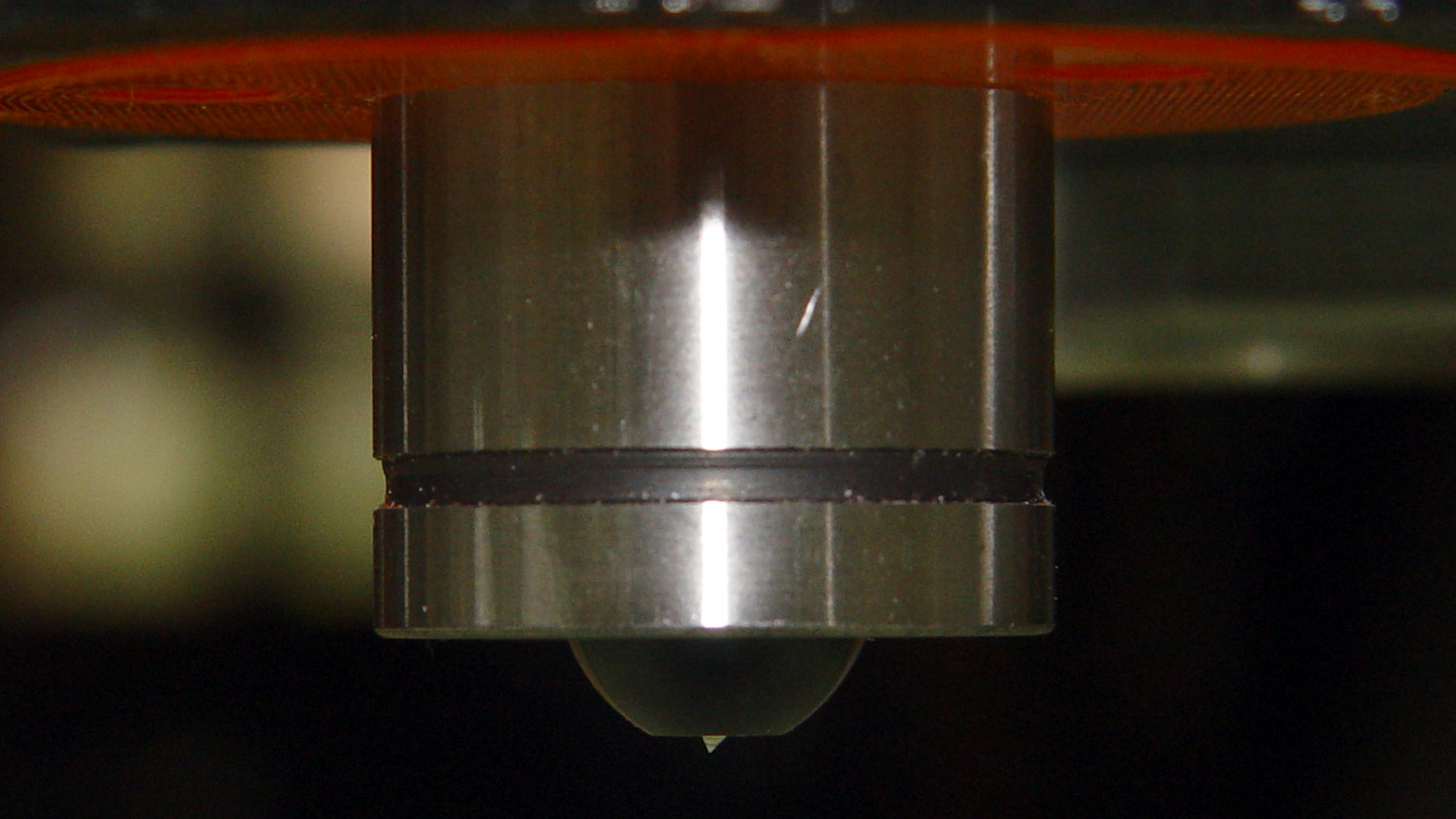
Because the knife body isn’t touching the bearing for the lower half of its length, it’ll probably deflect too much in the XY plane, but it’s simple enough to try out.
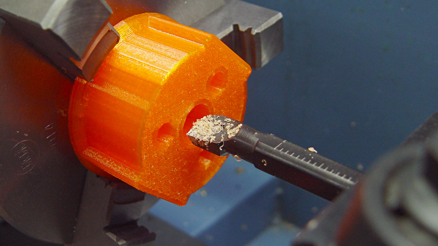
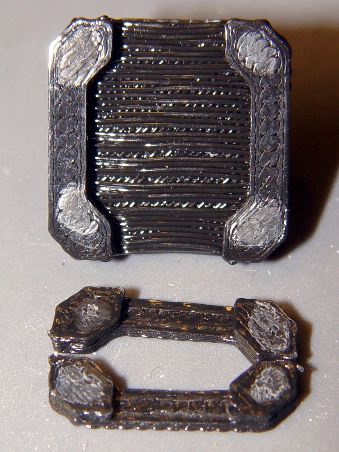
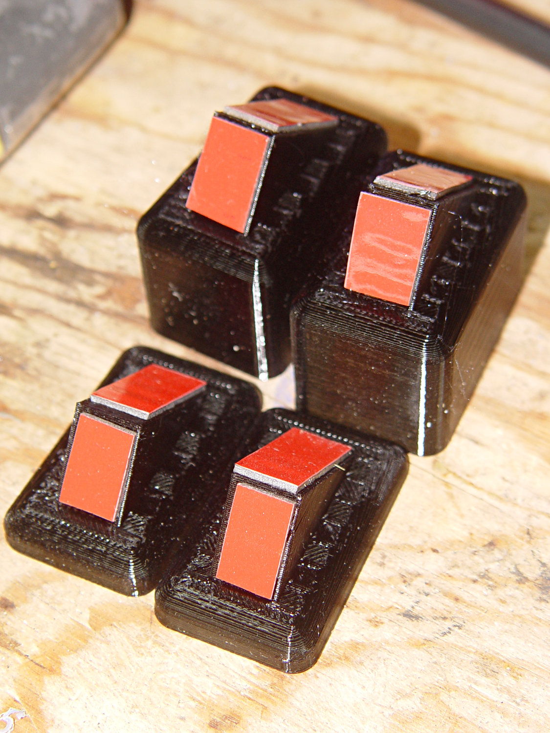
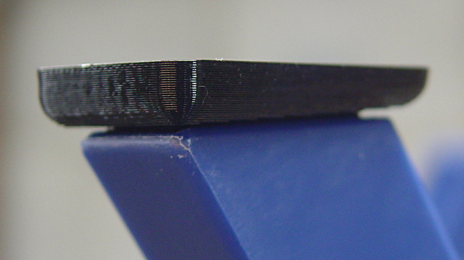
As before, the knife body’s flange is a snug fit in the hole bored in the upper disk:

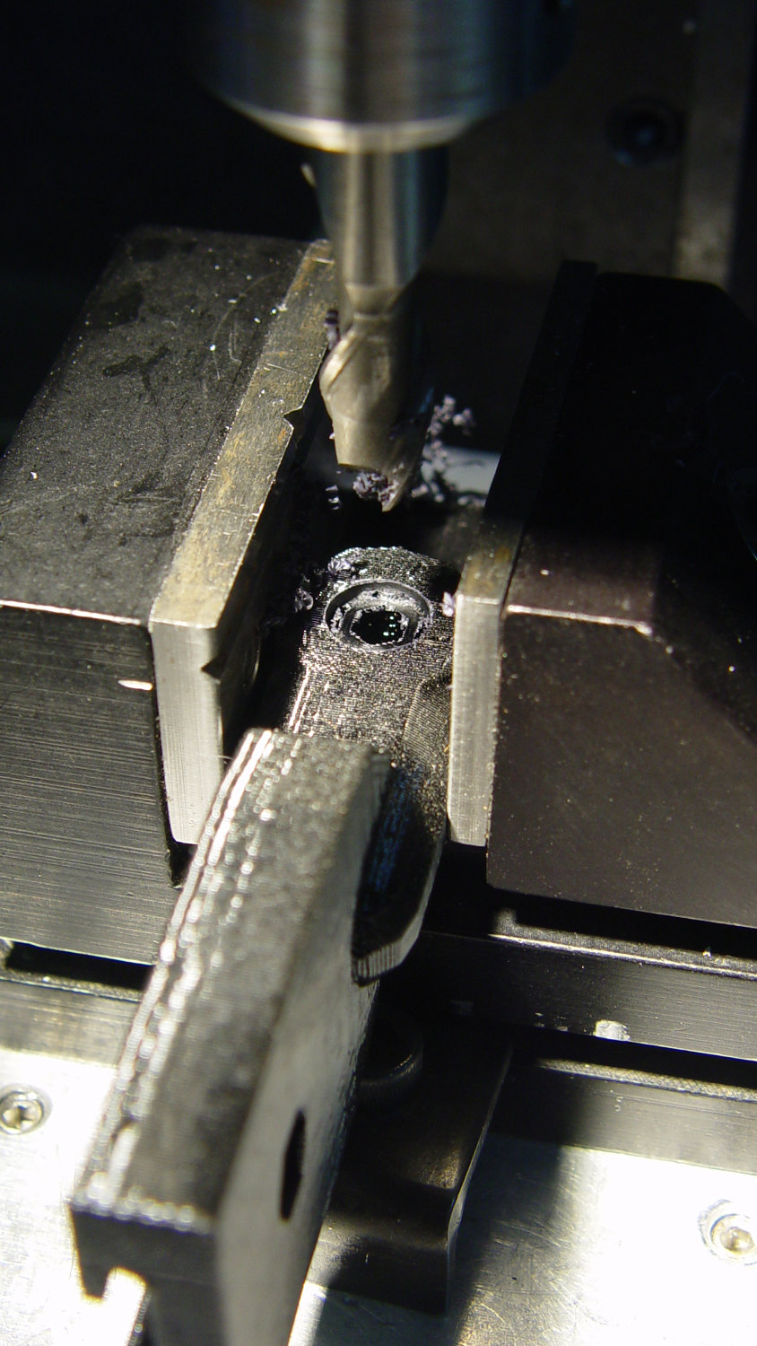
This time, I tried faking stripper bolts by filling the threads of ordinary socket head cap screws with epoxy:
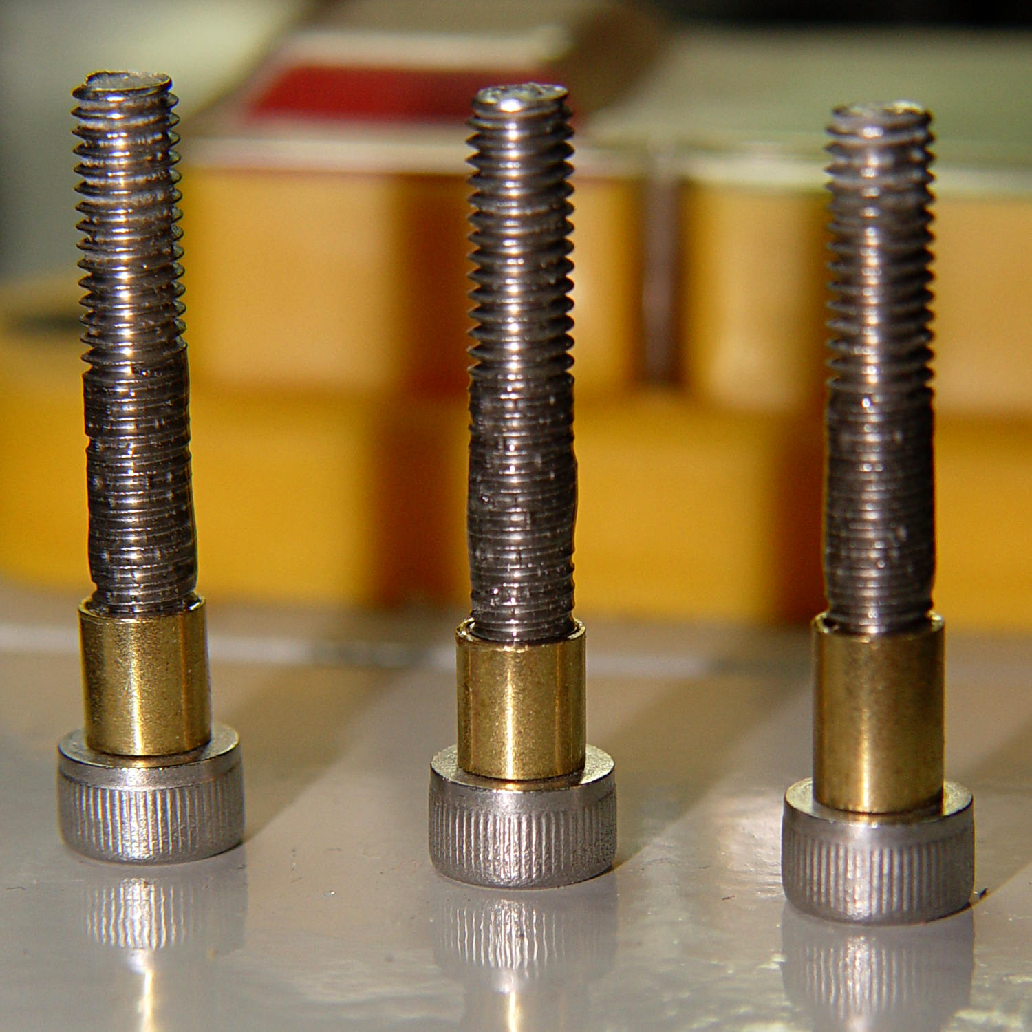
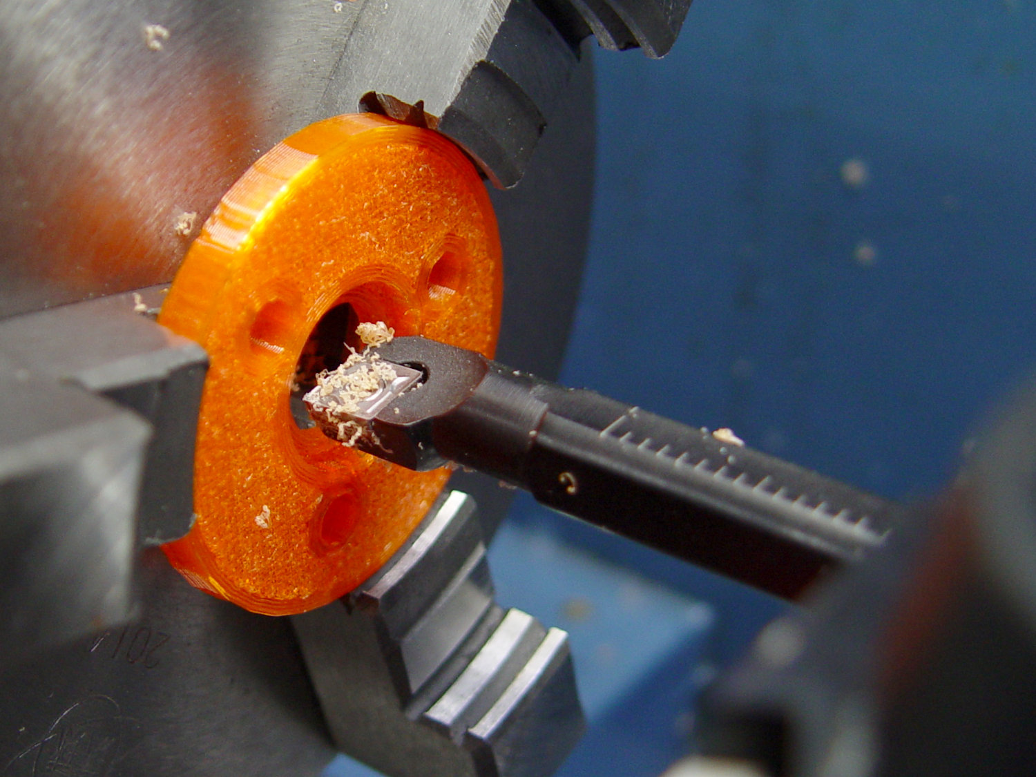
Turning the filled section to match the thread OD showed this just wasn’t going to work at all, so I turned the gunked section of the threads down to about 3.5 mm and continued the mission:

Next time, I’ll try mounting the disk on telescoping brass tubing nested around the screws. The motivation for the epoxy nonsense came from the discovery that real stainless steel stripper bolts run five bucks each, which means I’m just not stocking up on the things.
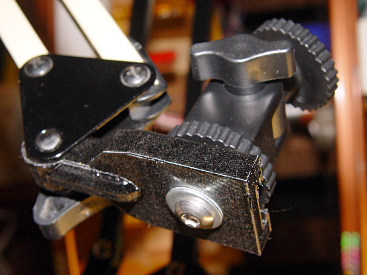
It slide surprisingly well on the cut-down screws, though:

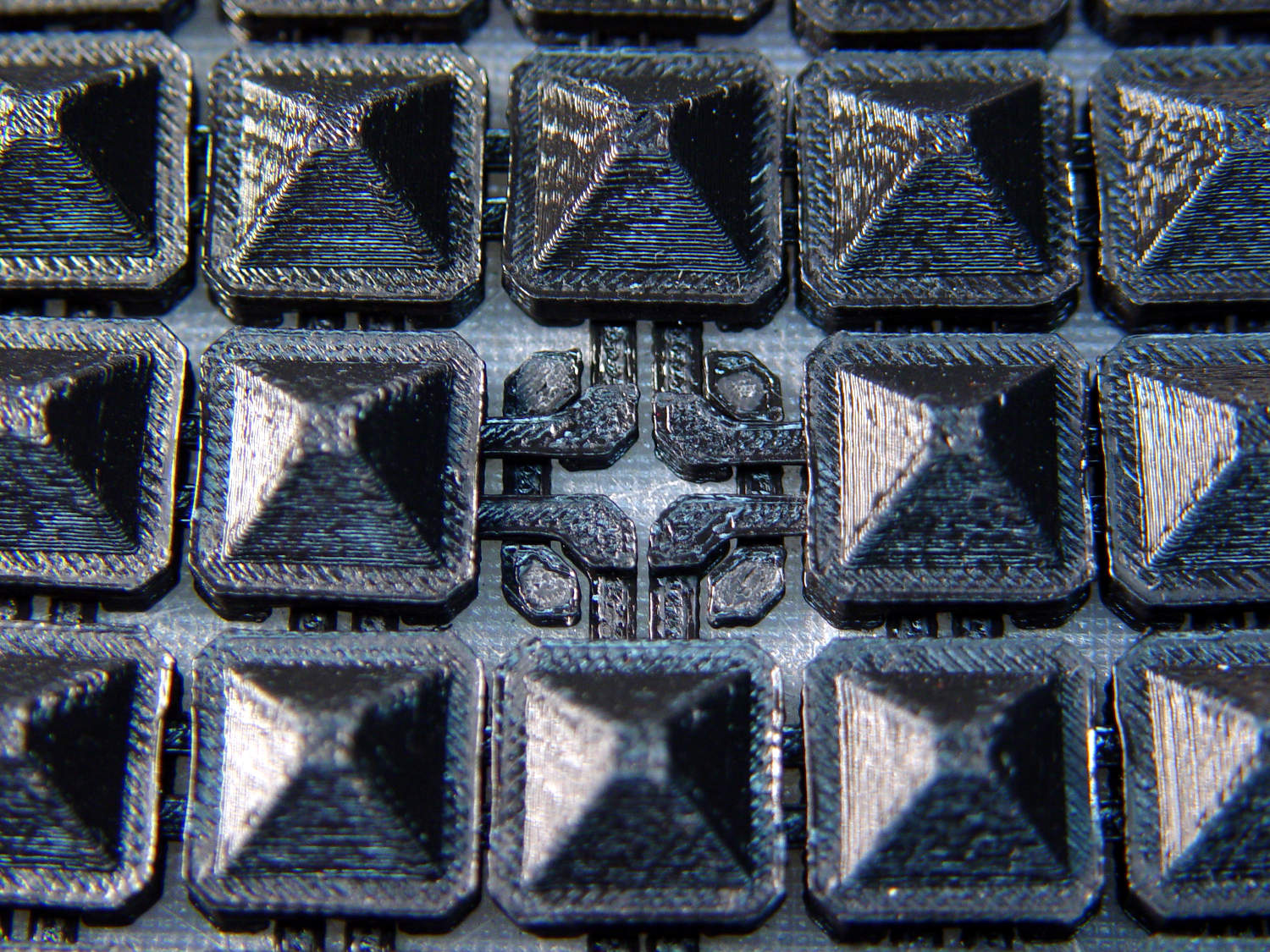
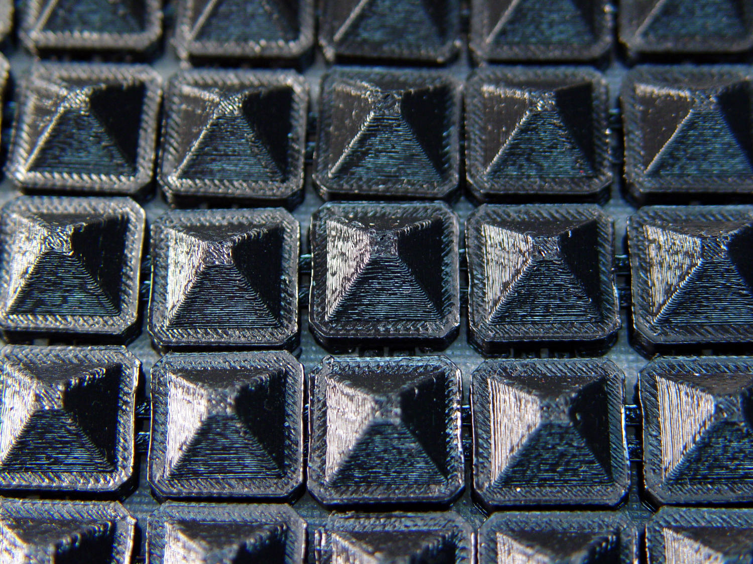
Those appliqué templates came from patterns for a block in one of Mary’s current quilting projects, so perhaps I can be of some use whenever she next needs intricate cutouts.
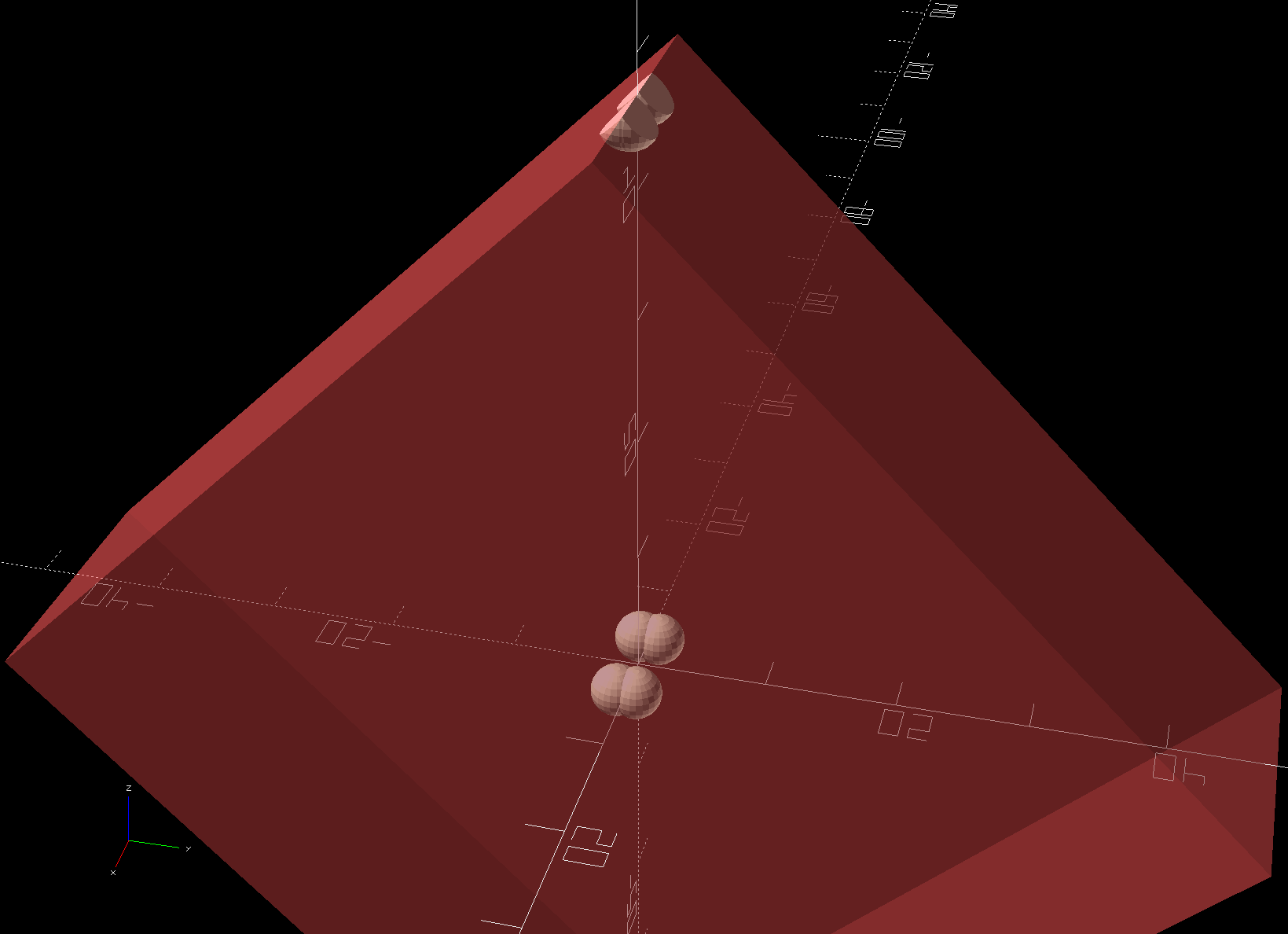
The OpenSCAD source code as a GitHub Gist:
| // Drag Knife Holder using LM12UU linear bearing | |
| // Ed Nisley KE4ZNU – 2019-04-26 | |
| Layout = "Show"; // [Build, Show, Puck, Mount, Plate] | |
| /* [Extrusion] */ | |
| ThreadThick = 0.25; // [0.20, 0.25] | |
| ThreadWidth = 0.40; // [0.40] | |
| /* [Hidden] */ | |
| Protrusion = 0.1; // [0.01, 0.1] | |
| HoleWindage = 0.2; | |
| inch = 25.4; | |
| function IntegerMultiple(Size,Unit) = Unit * ceil(Size / Unit); | |
| ID = 0; | |
| OD = 1; | |
| LENGTH = 2; | |
| //- Adjust hole diameter to make the size come out right | |
| module PolyCyl(Dia,Height,ForceSides=0) { // based on nophead's polyholes | |
| Sides = (ForceSides != 0) ? ForceSides : (ceil(Dia) + 2); | |
| FixDia = Dia / cos(180/Sides); | |
| cylinder(r=(FixDia + HoleWindage)/2,h=Height,$fn=Sides); | |
| } | |
| //- Dimensions | |
| // Basic shape of DW660 snout fitting into the holder | |
| // Lip goes upward to lock into MPCNC mount | |
| Snout = [44.6,50.0,9.6]; // LENGTH = ID height | |
| Lip = 4.0; // height of lip at end of snout | |
| // Knife holder & suchlike | |
| KnifeBody = [12.0,15.9,2.0]; // flange epoxied to top of diamond shaft, with epoxy fillet | |
| WallThick = 4.0; // minimum thickness / width | |
| Screw = [4.0,8.5,8.0]; // holding it all together, OD = washer | |
| Insert = [4.0,6.0,10.0]; // brass insert | |
| Bearing = [12.0,21.0,30.0]; // linear bearing body | |
| Plate = [KnifeBody[ID],Snout[OD] – WallThick,KnifeBody[LENGTH] + WallThick]; // spring reaction plate | |
| PlateGuide = [4.0,4.8,Plate[LENGTH]]; // … guide tubes | |
| PuckOAL = max(Bearing[LENGTH],(Snout[LENGTH] + Lip)); // total height of DW660 fitting | |
| echo(str("PuckOAL: ",PuckOAL)); | |
| Key = [Snout[ID],25.7,(Snout[LENGTH] + Lip)]; // rectangular key | |
| NumScrews = 3; | |
| ScrewBCD = 2.0*(Bearing[OD]/2 + Insert[OD]/2 + WallThick); | |
| NumSides = 9*4; // cylinder facets (multiple of 3 for lathe trimming) | |
| module DW660Puck() { | |
| translate([0,0,PuckOAL]) | |
| rotate([180,0,0]) { | |
| cylinder(d=Snout[OD],h=Lip/2,$fn=NumSides); | |
| translate([0,0,Lip/2]) | |
| cylinder(d1=Snout[OD],d2=Snout[ID],h=Lip/2,$fn=NumSides); | |
| cylinder(d=Snout[ID],h=PuckOAL,$fn=NumSides); | |
| intersection() { | |
| translate([0,0,0*Lip + Key.z/2]) | |
| cube(Key,center=true); | |
| cylinder(d=Snout[OD],h=Lip + Key.z,$fn=NumSides); | |
| } | |
| } | |
| } | |
| module MountBase() { | |
| difference() { | |
| DW660Puck(); | |
| translate([0,0,-Protrusion]) // bearing | |
| PolyCyl(Bearing[OD],2*PuckOAL,NumSides); | |
| for (i=[0:NumScrews – 1]) // clamp screws | |
| rotate(i*360/NumScrews) | |
| translate([ScrewBCD/2,0,-Protrusion]) | |
| rotate(180/8) | |
| PolyCyl(Insert[OD],2*PuckOAL,8); | |
| } | |
| } | |
| module SpringPlate() { | |
| difference() { | |
| cylinder(d=Plate[OD],h=Plate[LENGTH],$fn=NumSides); | |
| translate([0,0,-Protrusion]) // knife holder body | |
| PolyCyl(KnifeBody[ID],2*PuckOAL,NumSides); | |
| translate([0,0,Plate[LENGTH] – KnifeBody[LENGTH]]) // flange, snug fit | |
| PolyCyl(KnifeBody[OD],KnifeBody[LENGTH] + Protrusion,NumSides); | |
| for (i=[0:NumScrews – 1]) // clamp screws | |
| rotate(i*360/NumScrews) | |
| translate([ScrewBCD/2,0,-Protrusion]) | |
| rotate(180/8) | |
| PolyCyl(PlateGuide[OD],2*PuckOAL,8); | |
| } | |
| } | |
| //—– | |
| // Build it | |
| if (Layout == "Puck") | |
| DW660Puck(); | |
| if (Layout == "Plate") | |
| SpringPlate(); | |
| if (Layout == "Mount") | |
| MountBase(); | |
| if (Layout == "Show") { | |
| MountBase(); | |
| translate([0,0,1.6*PuckOAL]) | |
| rotate([180,0,0]) | |
| SpringPlate(); | |
| } | |
| if (Layout == "Build") { | |
| translate([0,Snout[OD]/2,PuckOAL]) | |
| rotate([180,0,0]) | |
| MountBase(); | |
| translate([0,-Snout[OD]/2,0]) | |
| SpringPlate(); | |
| } |