
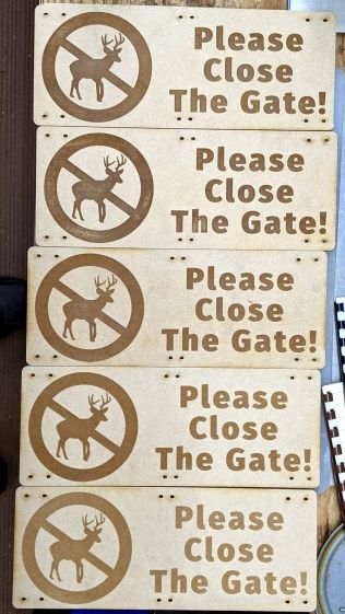
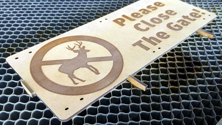
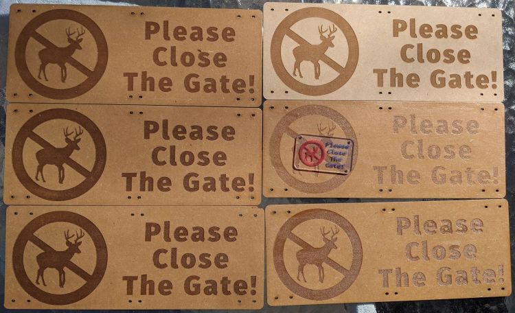
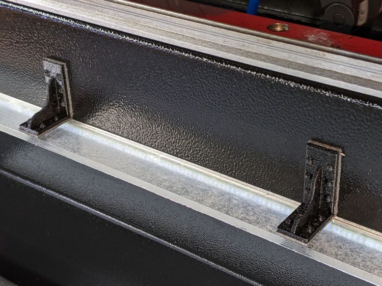
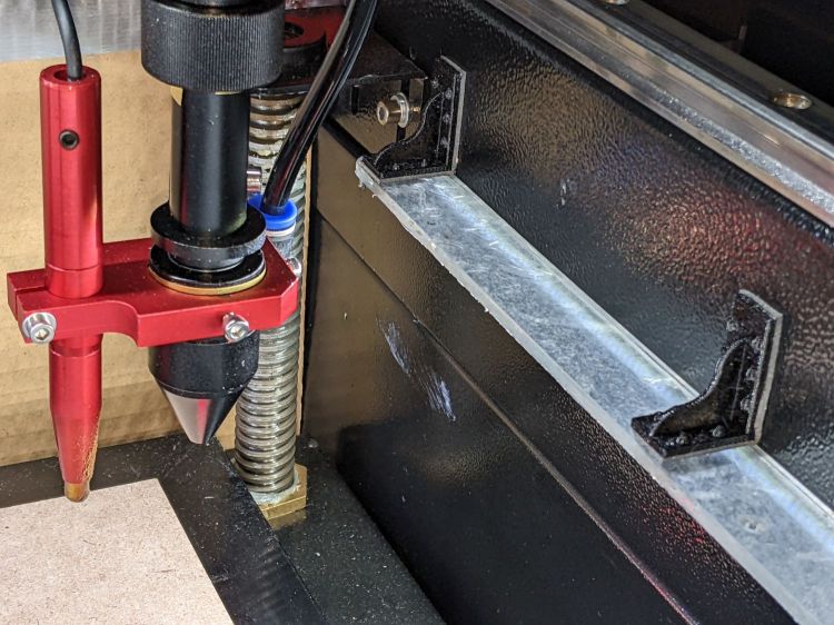
When you (well, I) get fussy about angular alignment on the laser cutter’s honeycomb platform, an adjustable stop or two may come in handy:

That’s a serving suggestion based on a true story, because I really wasn’t all that fussy about precise engraving alignment on those signs.
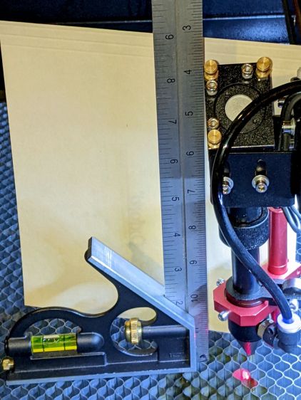
A more typical situation on a smaller scale:
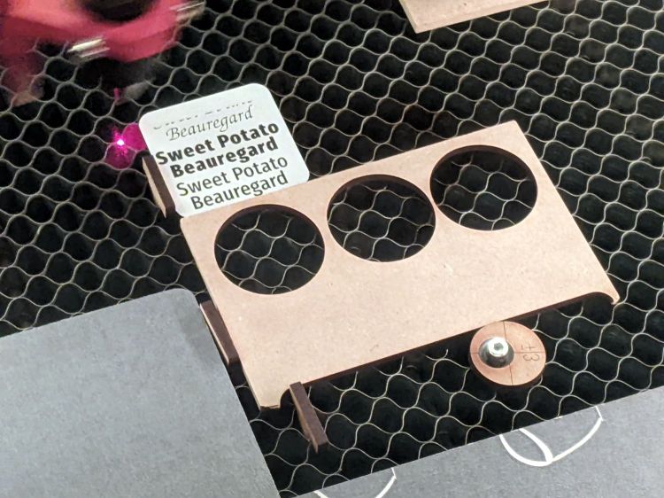
The scrap of MDF with three holes provides angular alignment for the little two-color acrylic test coupon, so you can tuck successive squares into the corner, hammer them with slightly different patterns, then compare the results.
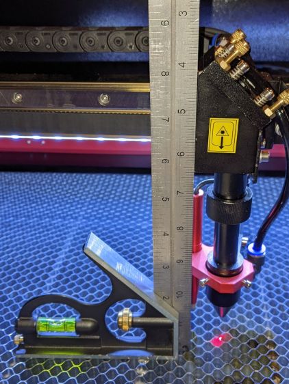
The stops are an off-center hole (the ±3 text gives the offset) in an MDF disk with an acetal post:

The 3 mm SHCS provides a convenient way to turn the post and disk, so the threading isn’t critical. Sufficiently snug threading will let you turn the screw counterclockwise without loosening it, but that surely depends on how tightly the 8 mm section fits into the honeycomb. The larger top section is 9mm, cleaned up from the rod’s nominal 3/8 inch OD, for a jam fit into the 8.8 mm + 0.1 mm kerf hole.
The SVG images as a GitHub Gist:
The ±5 mm offset disk may be more useful with larger items and now you know where those three holes came from.


