The Smell of Molten Projects in the Morning

Ed Nisley's Blog: Shop notes, electronics, firmware, machinery, 3D printing, laser cuttery, and curiosities. Contents: 100% human thinking, 0% AI slop.

Tag: Laser Cutter

  • Laser Air Assist Pump Filter: Ewww!

    Laser Air Assist Pump Filter: Ewww!

    Nine months ago I packed cheesecloth around the laser’s air assist pump inlet to filter the smog:

    OMTech 60 W Laser Air Assist - cheesecloth filter installed
    OMTech 60 W Laser Air Assist – cheesecloth filter installed

    Which worked better than I expected.

    I think the track on the right side of the lower / outer filter faced the interior of the cabinet and collected some incoming smog:

    Laser cutter assist air filter - 9 months - outer
    Laser cutter assist air filter – 9 months – outer

    The wad packed around the inlet fitting accumulated even more, due to the concentrated air flow through the round opening:

    Laser cutter assist air filter - 9 months - inner
    Laser cutter assist air filter – 9 months – inner

    Thus we can confirm putting the air pump inside the cutting chamber is not a particularly good idea:

    OMTech 60W laser - Z motor - air pump
    OMTech 60W laser – Z motor – air pump

    My initial notion of drilling a hole through the bottom of the cabinet so the pump can breathe relatively clean basement air takes on new urgency …

  • Tour Easy: SJCAM C100+ Mount

    Tour Easy: SJCAM C100+ Mount

    The batteries (which are no longer available) and the control buttons have worn out on the SJCAM M20 camera on the back of my Tour Easy, so a replacement is in order:

    Tour Easy - SJCAM C100 mount - installed
    Tour Easy – SJCAM C100 mount – installed

    It’s an SJCAM C100+ in its waterproof housing, screwed to a block descended from the M20 mount:

    SJCAM C100 Mount - solid model
    SJCAM C100 Mount – solid model

    The C100+ has a non-replaceable lithium pouch battery that may not last for the hour or so we generally ride, but at least this is a starting point for seeing how the thing works.

    The PrusaSlicer preview shows the support structure inside the seat rail arches:

    SJCAM C100 Mount - slicer
    SJCAM C100 Mount – slicer

    That appears under the four central facets of each arch, where I “painted” the support enforcers, because the automagic supports fill the entire arch and are basically impossible to pry off.

    The hole between the ears on the top holds an aluminum tab intended to diffuse the wobble from that tall camera. A laser-cut chipboard template simplified drilling & cutting the tab from an aluminum sheet:

    Tour Easy - SJCAM C100 mount - test fit
    Tour Easy – SJCAM C100 mount – test fit

    The tab and the brass inserts are held in place with JB Weld Plastic Bonder, my new go-to adhesive for such things.

    The camera includes WiFi and the inevitable app lets you download images without opening the case. Because I’ll be charging the camera after each ride, I may as well just haul the whole thing inside, plug it into a USB port, and proceed as before.

    For future reference, the manual details the operating modes:

    SJCAM C100 Manual - Modes
    SJCAM C100 Manual – Modes

    Because the camera powers up with WiFi enabled and I have no plans to communicate with it while riding, the startup sequence will be:

    • Long-press to power on
    • Double-click to disable WiFi
    • Single-click to start recording

    The OpenSCAD source code as a GitHub Gist:

    // SJCAM C100+ Camera Mount for Tour Easy seat back rail
    // Ed Nisley – KE4ZNU
    // 2023-04
    /* [Layout Options] */
    LookAngle = -20; // camera angle, looking backwards = 0°
    Layout = "Show"; // [Show,Build]
    /* [Hidden] */
    ThreadWidth = 0.40;
    ThreadThick = 0.25;
    HoleWindage = 0.2;
    Protrusion = 0.1;
    ID = 0;
    OD = 1;
    LENGTH = 2;
    //—–
    // Dimensions
    ClampScrew = [5.0,10.0,40.0]; // ID=thread OD=washer LENGTH=total
    ClampInsert = [5.0,7.5,10.5]; // brass insert
    MountScrew = [5.0,10.0,23.0]; // ID=thread OD=washer LENGTH=under nut
    MountInsert = [5.0,7.5,10.5]; // ID=screw OD, OD=knurl dia
    EmbossDepth = 2*ThreadThick + Protrusion; // recess depth + Protrusion beyond surface
    DebossHeight = EmbossDepth; // text height + Protrusion into part
    RailOD = 20.0; // slightly elliptical in bent section
    RailSides = 2*3*4;
    ClampOA = [60.0,40.0,ClampScrew[LENGTH]]; // set clamp size to avoid weird screw spacing
    echo(ClampOA = ClampOA);
    ClampScrewOC = IntegerMultiple(ClampOA.x – ClampScrew[OD] – 10*ThreadWidth,1.0);
    echo(ClampScrewOC = ClampScrewOC);
    ClampOffset = 5.0; // in case we need more room on top
    ClampRadius = 3.0;
    ClampSides = 8;
    Kerf = 1.0; // slice through the middle
    // center mount blade, Z = depth into block
    MountBlade = [15.0 + 2*HoleWindage,
    3.0 + 2*HoleWindage,
    (ClampOA.z – RailOD + ClampOffset)/2 – 4*ThreadThick + Protrusion];
    echo(MountBlade = MountBlade);
    MountRadius = MountBlade.x / 2;
    MountGap = 9.5; // camera mount gap around center blade
    MountOffset = [0,0,7.0]; // mount hole offset from block surface
    FadeColor = "Green";
    FadeAlpha = 0.25;
    //—–
    // Useful routines
    function IntegerMultiple(Size,Unit) = Unit * ceil(Size / Unit);
    module PolyCyl(Dia,Height,ForceSides=0) { // based on nophead's polyholes
    Sides = (ForceSides != 0) ? ForceSides : (ceil(Dia) + 2);
    FixDia = Dia / cos(180/Sides);
    cylinder(r=(FixDia + HoleWindage)/2,
    h=Height,
    $fn=Sides);
    }
    //—–
    // Clamp
    // Grips seat frame rail
    // Origin at middle of seat rail, X rearward, Y parallel to seat frame rail
    // Block offset raises whole thing
    module Clamp() {
    difference() {
    translate([0,0,ClampOffset]) {
    difference() {
    union() {
    hull() // the main block
    for (i=[-1,1], j=[-1,1], k=[-1,1])
    translate([i*(ClampOA.x – 2*ClampRadius)/2,
    j*(ClampOA.y – 2*ClampRadius)/2,
    k*(ClampOA.z – 2*ClampRadius)/2])
    sphere(r=ClampRadius/cos(180/ClampSides),$fn=ClampSides);
    hull() // camera mount boss
    for (k=[0,1])
    translate([0,0,k*(MountOffset.z) + ClampOA.z/2])
    rotate([0,90,LookAngle + 90]) rotate(180/12)
    cylinder(r=MountRadius,h=MountScrew[LENGTH],center=true,$fn=12);
    }
    for (i=[-1,1]) // clamp inserts
    translate([i*ClampScrewOC/2,0,-(ClampOA.z/2 + Protrusion)])
    rotate(180/6)
    PolyCyl(ClampInsert[OD],ClampInsert[LENGTH],6);
    for (i=[-1,1]) // clamp screw holes
    translate([i*ClampScrewOC/2,0,-ClampOA.z])
    rotate(180/6)
    PolyCyl(ClampScrew[ID],2*ClampOA.z,6);
    translate([0,0,ClampOA.z/2 – (MountBlade.z/2 – Protrusion/2)]) // camera center blade
    rotate(LookAngle)
    cube(MountBlade,center=true);
    rotate(LookAngle + 90) // camera mount boss slot
    translate([0,0,ClampOA.z/2 + 2*MountRadius])
    cube([MountGap,4*MountRadius,4*MountRadius],center=true);
    translate([0,0,ClampOA.z/2 + MountOffset.z]) // camera mount boss hole
    rotate([90,0,LookAngle])
    cylinder(d=MountScrew[ID],h=4*MountGap,center=true,$fn=6);
    translate([0.3*ClampOA.x, // recess for LookAngle legend
    -(ClampOA.y/2 – (EmbossDepth – Protrusion)/2),
    ClampOA.z/4])
    cube([15,EmbossDepth,8],center=true);
    translate([0,0,-ClampOA.z/2 + (EmbossDepth – Protrusion)/2]) // recess for ID legend
    cube([35,10,EmbossDepth],center=true);
    }
    translate([0.3*ClampOA.x, // LookAngle legend
    -ClampOA.y/2 + DebossHeight + Protrusion/2,
    ClampOA.z/4])
    rotate([90,0,00])
    linear_extrude(height=DebossHeight,convexity=20)
    text(text=str(LookAngle),size=6,spacing=1.20,
    font="Arial:style:Bold",halign="center",valign="center");
    translate([0,0,-ClampOA.z/2]) // ID legend
    linear_extrude(height=DebossHeight,convexity=20)
    mirror([0,1,0])
    text(text="KE4ZNU",size=5,spacing=1.20,
    font="Arial:style:Bold",halign="center",valign="center");
    }
    cube([2*ClampOA.x,2*ClampOA.y,Kerf],center=true); // split across rail
    rotate([90,0,0]) // seat rail
    cylinder(d=RailOD,h=2*ClampOA.y,$fn=RailSides,center=true);
    }
    }
    //—–
    // Build things
    // Layouts for design & tweaking
    if (Layout == "Show") {
    Clamp();
    color(FadeColor,FadeAlpha)
    rotate([90,0,0])
    cylinder(d=RailOD,h=2*ClampOA.y,$fn=RailSides,center=true);
    }
    // Build layout
    if (Layout == "Build") {
    translate([0,0.7*ClampOA.y,0])
    difference() {
    translate([0,0,-Kerf/2])
    Clamp();
    translate([0,0,-ClampOA.z])
    cube(2*ClampOA,center=true);
    }
    translate([0,-0.7*ClampOA.y,-0])
    difference() {
    translate([0,0,-Kerf/2])
    rotate([0,180,0])
    Clamp();
    translate([0,0,-ClampOA.z])
    cube(2*ClampOA,center=true);
    }
    }

  • Aperiodic Monotile Puzzle

    Aperiodic Monotile Puzzle

    The aperiodic monotile discovery prompted some reverse engineering, snapping a path to regular hexagons for the proper lengths and angles without mathing too hard:

    Aperiodic tile - hexagon overlay
    Aperiodic tile – hexagon overlay

    The resulting red path is the “hat” monotile, here shown as a PNG for neatness:

    Aperiodic monotile
    Aperiodic monotile

    With SVG hat in hand, I laid and cut a trial puzzle based on the sample shown in the paper:

    Aperiodic tile layout
    Aperiodic tile layout

    Which looked promising enough to add a few rings around that layout and turn it into an actual, albeit low budget, puzzle:

    Aperiodic tile puzzle - starting
    Aperiodic tile puzzle – starting

    The paper notes that one can build mutually incompatible patches, which is the state I immediately blundered into:

    Aperiodic tile puzzle - progress
    Aperiodic tile puzzle – progress

    The upper and lower left halves cannot be combined to extend rightward, as the middle section is incompatible with both. I began growing patches from the upper and lower right corners, hoping to use them to rectify the left half, but producing a small un-fillable situation in the middle:

    Aperiodic tile puzzle - incorrect layout
    Aperiodic tile puzzle – incorrect layout

    Obviously, I need a cheat code. I’m resolutely not looking at the source layout for a while.

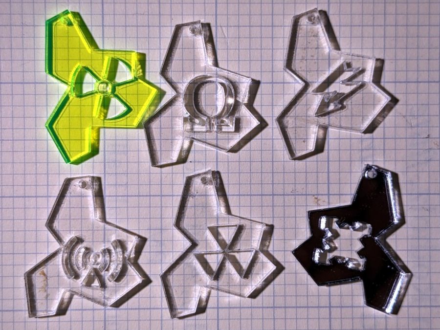
    This would surely look good in fluorescent edge-lit acrylic!

    The LightBurn SVG layout as a GitHub Gist:

    Loading
    Sorry, something went wrong. Reload?
    Sorry, we cannot display this file.
    Sorry, this file is invalid so it cannot be displayed.

  • Another CatEye Cadence Sensor Magnet Mount

    Another CatEye Cadence Sensor Magnet Mount

    The stock Bafang pedal cranks measure 170 mm on centers between the bottom bracket shaft and the pedal spindle. Having grown accustomed to the 165 mm cranks from Mary’s bike, I got a set of cheap 160 mm cranks to feel if there was any difference:

    Bafang vs ProWheel crank forging
    Bafang vs ProWheel crank forging

    The bottom crank has a quick-and-dirty adaptation of the magnet mount for the Lekkie Buzz Bar offset cranks, but, of course, the 160 mm cranks have an entirely different profile. They are also heavier and more crudely forged, which is about what you’d (well, I’d) expect.

    Also unlike the Lekkie cranks, neither the Bafang nor the Prowheel cranks correct the Bafang motor’s offset, so I’m using the left-side Kneesaver from the old cranks, which turns out to be close enough.

    Modeling the profile started with an infrequently used contour gauge:

    CatEye Magnet holder - ProWheel crank profile tests
    CatEye Magnet holder – ProWheel crank profile tests

    The black 3D printed mount in the upper right fit the Bafang crank and appears in the top photo.

    Transferring the new contour to paper and applying the Chord Equation got the radius of the not-quite circle:

    CatEye magnet crank adapter - chord radius
    CatEye magnet crank adapter – chord radius

    Knowing the size of the magnet and the radius of the circle, drawing the profile in LightBurn was straightforward:

    CatEye magnet crank adapter - framed
    CatEye magnet crank adapter – framed

    Applying the laser cutter to MDF produced the two successive test-fit pieces in the picture while figuring out how much stickout the magnet needed beyond the inner crank face to reach the sensor. LightBurn’s Node Editor simplified adjusting the size: drag-select a group of nodes, then move them in precise increments with the arrow keys.

    Export the profile from LightBurn as an SVG file, import it into OpenSCAD, and extrude it to the proper length:

    module CatEyeMagnet() {
    
    Magnet = [19.0,14.0,8.5];
    
    translate([0,75,0])
        linear_extrude(height=Magnet.y)
            import("CatEye magnet crank adapter.svg");
    
    }
    

    The translate puts the profile approximately at the XY origin. The center = true option moves the profile elsewhere on the XY plane, but does not center it, which may have something to do with the viewport used by LightBurn, the OpenSCAD version I’m using, or something else entirely.

    In any event, the 3D printed mount fits the crank and puts the magnet where it will do the most good:

    CatEye Magnet holder - ProWheel crank - installed
    CatEye Magnet holder – ProWheel crank – installed

    What looks like an obvious curvature mismatch comes from having the tape edge not quite squashed against the crank.

    I should poke a channel through it for a cable tie around the crank, but that 3M foam tape is really good stuff and hasn’t failed me yet.

  • Under-cabinet Dell Sound Bar Mount

    Under-cabinet Dell Sound Bar Mount

    Another bedroom rearrangement ejected the Raspberry Pi streaming media player in favor of a phone and Bluetooth speaker, which meant I could convert the under-shelf mount into an under-cabinet mount:

    Under-cabinet sound bar mount
    Under-cabinet sound bar mount

    It’s basically ten identical identical spacers cut from 3 mm plywood, with a side benefit of dramatically reducing my scrap plywood stash, then skewered by a pair of absurdly long 4 mm self-tapping metal screws into holes drilled half an inch into the ¾ inch solid wood cabinet floor.

    It clears some clutter atop the microwave and, at least to my deflicted ears, sounds much better. At some point I must screw the Raspberry Pi under the cabinet, too, but that awaits further rearrangement.

  • Bafang DPC-18 Button Mollyguard

    Bafang DPC-18 Button Mollyguard

    I got the Bafang DPC-18 display for my Tour Easy specifically to put the control buttons on the handgrip, rather than the buttons on the left of the 500C display on Mary’s bike:

    Tour Easy Bafang - display 26 mi
    Tour Easy Bafang – display 26 mi

    The first pass put them on the left handgrip, just behind the thumb throttle:

    Bafang DPC-18 control buttons - initial mount
    Bafang DPC-18 control buttons – initial mount

    This turned out to be a catastrophically bad position, because the “buttons” extend all the way to the edge of the mount and trigger when pressed a fraction of a millimeter: the dark line visible under the light gray top is the entire range of motion.

    My resting hand position on the grip put the edge of my gloved index finger along the buttons, where it would inexorably nudge the + button until I was riding in assist level 9 (Rocket Sled) mode.

    One ride was enough to convince me those buttons needed a Mollyguard:

    PXL_20230321_233854755 - Bafang DPC-18 button Mollyguard - rear view
    PXL_20230321_233854755 – Bafang DPC-18 button Mollyguard – rear view

    It is, of course, a laser-cut piece of 1.5 mil black acrylic, held in place with hot-melt glue. Because the button housing isn’t mounted symmetrically on the handlebar, I cut a few paper templates before getting the position and size right.

    A view from the front shows the lip sticking up over the buttons:

    Bafang DPC-18 button Mollyguard - front view
    Bafang DPC-18 button Mollyguard – front view

    FWIW, the asymmetric mount put the buttons on the rider’s side of the flat handlebars found on contemporary upright city-rider style bikes. It makes perfect sense in that context, but didn’t help me in the least.

    With the Mollyguard in place, I rotated the whole button assembly around the handgrip to allow pushing the buttons with my thumb in its natural position.

    Now the assist level changes only when I want it to!

  • Eyeglass Case Padding

    Eyeglass Case Padding

    The “live hinge” on my overnight eyeglass case shattered when it hit the floor (these things happen), which prompted me to finish a longstanding project of replacing the inadequate / worn out padding in my most-used cases to reduce rattles while in my pocket.

    I’d long ago cut craft foam sheets to fit some of the cases, so I started by scanning a sample:

    Zenni case pad
    Zenni case pad

    Admittedly, black foam on a white background isn’t much to look at, but it did fit one of the cases pretty well.

    Rotate the image to make things simple, convert it into a monochrome bitmask, import it into LightBurn, fair some Bezier curves around it, duplicate and tweak for the other not-quite half of the case:

    Zenni eyeglass case pads - LB Layout
    Zenni eyeglass case pads – LB Layout

    I ended up with several different versions for various cases, but you get the general idea:

    Zenni eyeglass case pads - installed
    Zenni eyeglass case pads – installed

    They’re all cut from 2 mm EVA foam sheets which, despite the “vinyl” in their name, do not contain chlorine and are suitable for laser cuttery.

    Some of the deeper case halves required strips of adhesive sheet to secure the foam, but most sheets dry-fit in place.

    Definitely no rattles!