The Smell of Molten Projects in the Morning

Ed Nisley's Blog: Shop notes, electronics, firmware, machinery, 3D printing, laser cuttery, and curiosities. Contents: 100% human thinking, 0% AI slop.

Tag: Laser Cutter

  • Craft Stick Plant Markers: Print-and-Cut Alignment

    Craft Stick Plant Markers: Print-and-Cut Alignment

    With the text laid out in the template, start LightBurn’s Print-and-Cut Wizard to align the template with the fixture on the laser platform.

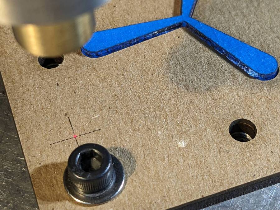
    Jog the laser to the upper-right target on the fixture, click the upper-right target in the template, and tell P-n-C that’s the First Target. Jog to the lower-left target, click the lower left target, and that’s the Second P-n-C Target:

    Craft Stick Markers - fixture target detail
    Craft Stick Markers – fixture target detail

    The colored circles indicate the targets on the template:

    Craft Stick Markers - LB PnC layout
    Craft Stick Markers – LB PnC layout

    Select the Align No Scaling option, because the template and the fixture are exactly the same size.

    Click-n-drag to select the entire template (because you should always use Cut Selected Graphics), then frame it Just To Be Sure. The red dot pointer (or whatever you use) should kiss the fixture’s perimeter all the way around.

    Make sure the fill layer happens before the cut layer, then Release The Laser:

    Craft Stick Markers - engraving
    Craft Stick Markers – engraving

    The cut layer trims around the engraved letters to leave them standing in the rectangle:

    Craft Stick Markers - cutting
    Craft Stick Markers – cutting

    Some of the smaller bits won’t fall out as they’re cut, but a sharp thwack ejects them easily enough.

    Producing a set of ten sticks takes maybe seven minutes:

    Craft Stick Markers - fixture second fill
    Craft Stick Markers – fixture second fill

    Because craft sticks aren’t intended for fine woodworking, don’t expect consistent engraving results:

    Craft Stick Markers - wood engraving difference
    Craft Stick Markers – wood engraving difference

    Applying a finish would definitely improve their appearance, but most such chemicals don’t belong in an organic vegetable garden.

    I poked the first few test sticks along the edge of the herb garden:

    Craft Stick Markers - test sticks installed
    Craft Stick Markers – test sticks installed

    The rest will be deployed as their eponymous plants go in, then we’ll see how long they survive out there in the real world.

    They’re kinda cute and definitely improved my fixture / template skillz.

  • Craft Stick Plant Markers: Layout Template and Text Alignment

    Craft Stick Plant Markers: Layout Template and Text Alignment

    Putting the entire fixture layout onto a tool layer produces a template to align the text on the sticks:

    Craft Stick Plant Markers - fixture layout
    Craft Stick Plant Markers – fixture layout

    The rectangles mark where you put cut layer rectangles around the text in each stick. The sticks are 18 mm wide, so a 10 mm cutout leaves what should be enough wood along the edges. The rectangle length is a serving suggestion, as you must adjust the cut rectangle to fit the text.

    Group everything except the four targets into a single object so you won’t inadvertently move only a part of it. The targets must remain separate to work with the Print-and-Cut alignment. With that set up, Lock the position of the entire layout to prevent you from moving any part of it.

    Starting with a blank tag in the template:

    Craft Stick Markers - LB template - base
    Craft Stick Markers – LB template – base

    Draw a rectangle in a cut layer to match the template, which is easy if you have Object Snap set up properly:

    Craft Stick Markers - LB template - rectangle
    Craft Stick Markers – LB template – rectangle

    Add your text in a chunky font like Fira Sans Condensed Heavy, set to 15 mm tall with 5 mm horizontal spacing:

    Craft Stick Markers - LB template - lowercase text
    Craft Stick Markers – LB template – lowercase text

    LightBurn aggressively snaps a new text cursor to the nearest pre-existing text, so you may be forced to click far away from where you want to place the text, type the text, then move the finished string. LightBurn will also snap the text to the display grid as you drag it around, so hold the Ctrl key down to disable snapping while you eyeball the proper alignment with the rectangle. Leave about 2 mm between the left edge of the rectangle and the first letter to make an easily visible space.

    Although you can use lowercase letters, uppercase letters have the compelling advantage of being attached both top and bottom, so retype the text if you forgot about the Caps Lock key:

    Craft Stick Markers - LB template - uppercase aligned
    Craft Stick Markers – LB template – uppercase aligned

    The 15 mm font height I’m using seems to be the overall maximum from the top of the tallest letter to the bottom of the lowest descender, not the height of any specific capital letter, all of which extend beyond the cut rectangle by about half a millimeter. That’s crucial to make this thing work, so tune the font and its height appropriately.

    Select the text string when you have it properly aligned:

    Craft Stick Markers - LB template - text selected
    Craft Stick Markers – LB template – text selected

    Hit Ctrl-D to duplicate the text, tap the ↑ (Up) arrow key to move the copy out of the way, and set it to the fill layer.

    Now the magic happens.

    Select the rectangle, Shift-select the text, and Boolean Subtract (Alt minus) the text from the rectangle:

    Craft Stick Markers - LB template - subtracted text
    Craft Stick Markers – LB template – subtracted text

    Realize that you have screwed up by not shortening the right side of the rectangle to leave about 2 mm of open space. Bang on Ctrl-Z to undo the last step, shorten the rectangle, Shift-select the text again, then subtract the text from the rectangle:

    Craft Stick Markers - LB template - properly subtracted text
    Craft Stick Markers – LB template – properly subtracted text

    Select the filled copy and whack the ↓ (Down) arrow key to move it back over the cut layer:

    Craft Stick Markers - LB template - overlaid text
    Craft Stick Markers – LB template – overlaid text

    Now the filled layer will toast the characters to a nice brown and the cut layer will remove the background rectangle.

    After finishing the text dance for all the markers, the template should look something like this:

    Craft Stick Markers - LB PnC layout
    Craft Stick Markers – LB PnC layout

    The cheerful circles come from LightBurn’s Print-and-Cut Wizard aligning the template with the fixture holding the craft sticks on the laser platform, about which more tomorrow.

  • Craft Stick Plant Markers: Laser Fixture

    Craft Stick Plant Markers: Laser Fixture

    Converting craft sticks into plant markers should be a mass-production process, which means a fixture is in order:

    Craft Stick Markers - fixture first fill
    Craft Stick Markers – fixture first fill

    Admittedly, making ten markers at once barely qualifies as “mass production”, but you (well, I) can think of it a proof of concept.

    The basic shape comes from a 0.25 mm outset around the measured size of a craft stick (150×18 mm), plus an alignment target:

    Craft Stick Plant Markers - fixture cut layout - array base
    Craft Stick Plant Markers – fixture cut layout – array base

    A good rule of thumb says never do any more work than absolutely necessary, so the rest of the fixture comes from linear arrays replicating the stick slots and targets:

    Craft Stick Plant Markers - fixture cut layout - full
    Craft Stick Plant Markers – fixture cut layout – full

    The two strips over on the left (with a common cut down the middle) get glued to the underside of the fixture:

    Craft Stick Markers - fixture rail gluing
    Craft Stick Markers – fixture rail gluing

    They’re exactly 5 mm apart to bracket one of the knife-edge bars supporting the fixture. The bar is upside-down to put its flat side upward:

    Craft Stick Markers - fixture target detail
    Craft Stick Markers – fixture target detail

    Yes, the fixture is made of chipboard, mostly because it’s about the same thickness as a craft stick and it’s cheap & readily available. Each target gets an ink blot to make it more conspicuous; there is also a tiny hole burned through the chipboard at the center to mark the other side for the strips.

    Two knife-edge bars (sharp side up) support the sticks near their ends, well out of the cutting path, to prevent scorch marks:

    Craft Stick Markers - fixture overview
    Craft Stick Markers – fixture overview

    It’s worth noting the knife-edge bars are 5 mm wide and the platform spaces them on 3/8 inch = 9.525 mm centers. Not 10 mm, not 9.5 mm, exactly 3/8 inch. Kinda like the platform leadscrews: a 4 mm lead thread driven by a belt with 0.2 inch pitch. Only in America.

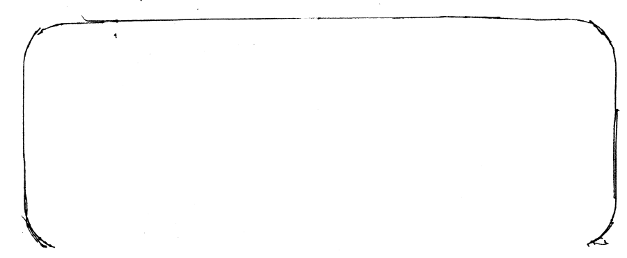
    This doodle captures the key dimensions down there in the corner to work out where the strips should go:

    Craft Stick Plant Markers - fixture vs laser bar spacing doodle
    Craft Stick Plant Markers – fixture vs laser bar spacing doodle

    Now, to convert names from a garden map into plant markers …

  • Plant Markers: Craft Stick Edition

    Plant Markers: Craft Stick Edition

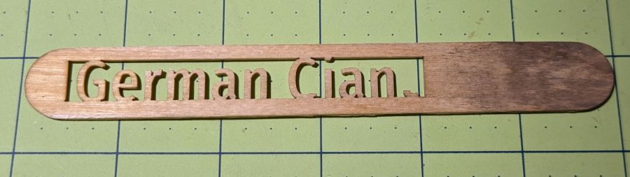
    Inspired by a LightBurn forum post I can no longer find once again tracked down, I tried my hand at popsicle craft stick plant markers:

    Plant Markers - craft stick tests
    Plant Markers – craft stick tests

    You’d have only one name on the end of each stick, with the uncut section jammed into the ground: these are test pieces to demonstrate capability.

    Wood is better than acrylic because it checks all the eco-friendly attribute boxes. Admittedly, craft sticks don’t exactly grow on trees, but we seem to ignore such externalities in nominally eco-friendly products.

    Bonus: a recurring revenue stream from the replacement market!

    The design, such as it is, involves subtracting the letters from a rectangle maybe half a millimeter short of their top & bottom extents and a few millimeters longer than their length. Using a chonky font with generous letter spacing may prevent prompt disintegration by weathering:

    Plant Marker - craft sticks - LB layout
    Plant Marker – craft sticks – LB layout

    Engraving the letters marks their uncut sections outside the rectangle, although we know laser char on wood-ish materials fades in sunlight. The two big sticks have Radish engraved with varying density; the darker version looks better against a lighter background never found in an actual garden.

    Mary thinks they might be a nice fundraiser for the next Master Gardener Plant Sale.

    Outdoor field tests seem appropriate …

  • Tour Easy Running Light: Heatsink Machining

    Tour Easy Running Light: Heatsink Machining

    Having acquired some thick-wall (1 inch OD, ¾ inch ID) aluminum tube, making the LED heatsink and lens holder for a running light generates a lot less scrap. A new doodle gives the dimensions in a rather Picasso-ish layout:

    Running Light - dimension doodles
    Running Light – dimension doodles

    The back end of the tube gets turned down to 23 mm OD and cleaned up to 19 mm ID, then scored to give the epoxy something to grip:

    Front Running Light - Heatsink shell scoring
    Front Running Light – Heatsink shell scoring

    The front end gets bored to 22.5 mm for the lens holder and has its OD cleaned up to 25 mm:

    Front Running Light - finished shell
    Front Running Light – finished shell

    Clean up the end of a ¾ inch rod to 19 mm OD, knurl it a little to increase the OD ever so slightly and improve its griptivity, slice off a bit more than 10 mm, butter it up with JB Weld epoxy, and shove it into the shell with its front end aligned and its back end sticking out:

    Front Running Light - epoxied plug in shell - rear
    Front Running Light – epoxied plug in shell – rear

    Face off the back end and the front end looks fine as assembled:

    Front Running Light - epoxied plug in shell - front
    Front Running Light – epoxied plug in shell – front

    Grab it in the Sherline mill’s three jaw chuck to:

    • Drill & tap the M3 central hole for the stud holding the circuit plate to the back end
    • Drill 1.6 mm blind holes for the circuit plate pins
    • Drill 2 mm through holes for the LED wires, 60° apart

    Which looks like this from the front:

    Front Running Light - drilled heatsink - front
    Front Running Light – drilled heatsink – front

    And like this with the circuit plate screwed & glued to the rear:

    Front Running Light - circuit plate mounted
    Front Running Light – circuit plate mounted

    Clean up the OD of some ¾ inch PVC pipe to 25 mm, bore it out to 23 mm.

    While the Sherline is set up, drill a pair of 2 mm holes in the lens holder for the wires, aligned so they’ll match the heatsink holes.

    Because we live in the future, laser-cut the rear cap from some edge-lit acrylic with a black inner disk:

    Front Running Light - PVC tube - end cap
    Front Running Light – PVC tube – end cap

    Cutting that cap with the notch included is now trivially easy, compared to the previous machining.

    Now for some circuitry …

  • Laser-engraved Polycarbonate: Color!

    Laser-engraved Polycarbonate: Color!

    Prompted by a LightBurn forum discussion, this was completely unexpected:

    Polycarbonate engrave - 400mm-s 20pct 0.1mm - brushed
    Polycarbonate engrave – 400mm-s 20pct 0.1mm – brushed

    The color is apparently a side effect of the CO₂ laser vaporizing the plastic, because it emerged during the engraving process.

    Polycarb tends to get all melty when cut, so it’s not particularly good for laser machining. Indeed, the engraving produced filaments of (presumably) melted / condensed plastic that I brushed off after taking this picture:

    Polycarbonate engrave - 400mm-s 20pct 0.1mm - as cut
    Polycarbonate engrave – 400mm-s 20pct 0.1mm – as cut

    If you could put up with the filaments and the poor cut edges, it might be useful for front panel legends and suchlike.

  • Laser Air Assist Pump Snorkel

    Laser Air Assist Pump Snorkel

    Having verified that putting an assist air pump inside the laser cabinet is a Bad Idea™, I set about building a fitting to attach to the air pump’s inlet connection:

    OMTech 60 W Laser Air Assist - pump inlet
    OMTech 60 W Laser Air Assist – pump inlet

    Note that it’s possible to see the inlet, but not do much with it. I think the bottom plate could be pried off those squishy rubber pillars supporting / isolating the pump, but I didn’t see any need to do so.

    The doodle I made at the time gives the dimensions:

    OMTech 60 W Laser Air Assist - pump inlet fitting measurements
    OMTech 60 W Laser Air Assist – pump inlet fitting measurements

    Back then, I thought of 3D printing the fitting, but the fact that the parts had to be 1.5 mm thick suggested laser cutting the parts from acrylic sheet:

    Laser cutter air pump - keyed fitting A - parts
    Laser cutter air pump – keyed fitting A – parts

    The three top disks come from a 3M LSE adhesive sheet and hold the three layers together, with one spare because I know better than to cut exactly as many as I think I’ll need:

    Laser cutter air pump - keyed fitting - assembled
    Laser cutter air pump – keyed fitting – assembled

    The alert reader will note the middle layer in that picture isn’t a simple round disk. After putting the first version together, I realized the keyed bottom layer could continue turning until it fell out, so I added stops to the middle disk:

    Laser cutter air pump - keyed fitting B - parts
    Laser cutter air pump – keyed fitting B – parts

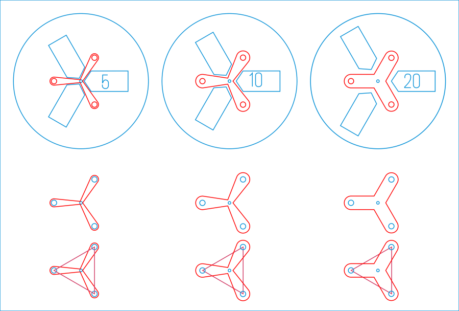
    Those stops came from the bottom layer layout by welding together three copies of the key opening:

    Laser Cutter Air Assist Pump Fitting - LB design layout
    Laser Cutter Air Assist Pump Fitting – LB design layout

    Space three of those shapes around the ring, subtract them from the outer disk (the same size as the keyed layer), weld them to the middle disk (the same size as the previous middle), and the stops appear as if by magic. Gotta love this geometry stuff.

    The same design produced matching adhesive disks that I applied with tweezers, but if you were doing it in production you’d definitely want to apply a sheet of adhesive to a sheet of acrylic and cut them in the same operation.

    Soften the slightly curved PVC tubing with a heat gun, persuade it to become straight, jam a drill bit inside and grab it in the lathe chuck to keep the fitting perpendicular, glob hot-melt glue around the tubing to hold it in place, and let it cool:

    Laser cutter air pump - fitting hose glue
    Laser cutter air pump – fitting hose glue

    Hot melt glue doesn’t adhere well to acrylic, so cut & apply a disk of LSE adhesive between them, because it sticks like … glue … to both substances.

    Mark and step-drill a hole in the bottom of the laser cabinet, install the fitting on the pump, line things up, and it’s ready to screw down:

    Laser cutter air pump - first trial fitting
    Laser cutter air pump – first trial fitting

    Whereupon I discovered the four silicone rubber feet I added to support the pump base plate and keep it from vibrating against the cabinet let the flexy rubber posts supporting the pump extend too far, thus causing the whole pump to rest on the glue around the fitting.

    Well, I can fix that and, while I’m at it, a snippet of fibrous stuff will keep the tube from rattling around:

    Laser cutter air pump - bottom view - assembled
    Laser cutter air pump – bottom view – assembled

    The four clear disks are 3 mm acrylic stuck to the rubbery feet with more LSE adhesive, with rings around the top to keep everything aligned. It may be possible to line up all four of those things while lowering the pump in place, but not for me.

    With all that once again ready to screw down, the blue tube and its fuzzy felt bumper fell right off, taking the pump’s air inlet connector along. Much to my surprise, the pump draws air through a simple 6 mm hole in its bottom plate:

    Laser cutter air pump - without fitting socket
    Laser cutter air pump – without fitting socket

    Now, the reason I went through all these gyrations was because I had examined that connector, decided it was an integral part of the pump, and there was no way for me to get it off without tearing the pump apart or applying brute force.

    Apparently, all the twisting & turning I did while getting the fittings assembled worked the connector’s unthreaded stem loose in its hole, ready to come out with the slightest pull.

    Verily: Hell hath no fury like that of an unjustified assumption.

    So I cut out a simple disk of 4.5 mm acrylic, hot-melt blobbed a 6 mm ID silicone tube into it, stuck it onto the pump with a (punch-cut!) disk of 3M double-sided foam tape, and declared victory:

    Laser cutter air pump - simple disk fitting
    Laser cutter air pump – simple disk fitting

    Fortunately, the step drill I used on the cabinet left a 9.5 mm hole easily passing the silicone tube’s 9 mm OD, so it all fit together just like I knew what I was doing.

    The silicone tubing has a much larger ID than the original plastic fitting, but the assist air flow remains around 10 l/min. That’s down from the 14 l/m when I installed the flowmeter and 12 l/min with the dual-path assist air control plumbing, but didn’t change with all this fiddling, so the real restriction is in all the blue tubing and myriad fittings on the way to the nozzle.

    On the upside, I now know a bit more about small-scale laser cutting and am well-satisfied with the results.