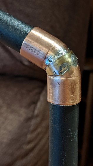
After five gardening seasons, my simple 3D printed wrench broke:

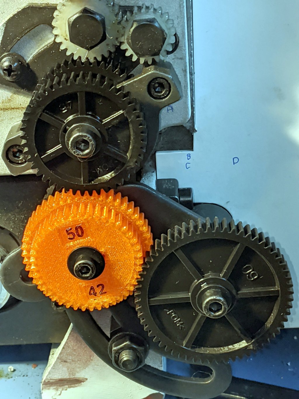
Although Jason’s comment suggesting carbon-fiber reinforcing rods didn’t prompt me to lay in a stock, ordinary music wire should serve the same purpose:
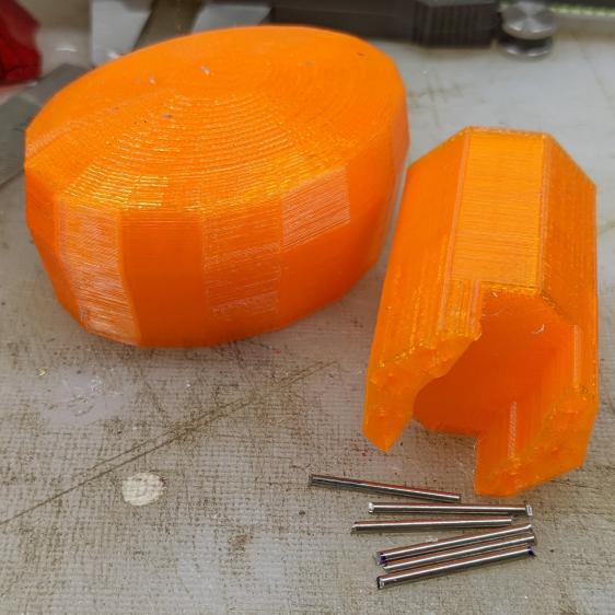
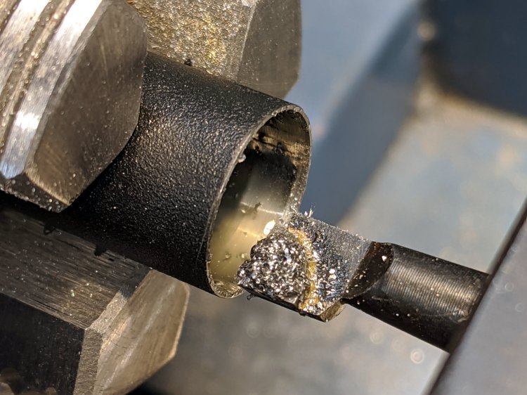
The pins are 1.6 mm diameter and 20 mm long, chopped off with hardened diagonal cutters. Next time, I must (remember to) grind the ends flat.
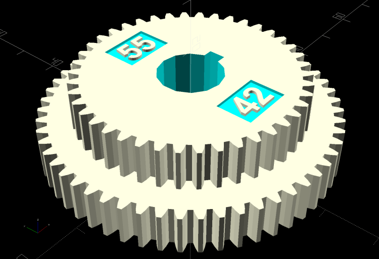
The solid model needs holes in appropriate spots:

Yes, I’m going to put round pins in square holes, without drilling the holes to the proper diameter: no epoxy, no adhesive, just 20 mm of pure friction.
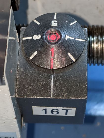
The drill press aligns the pins:
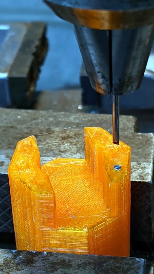
And rams them about halfway down:
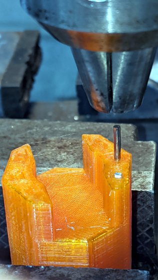
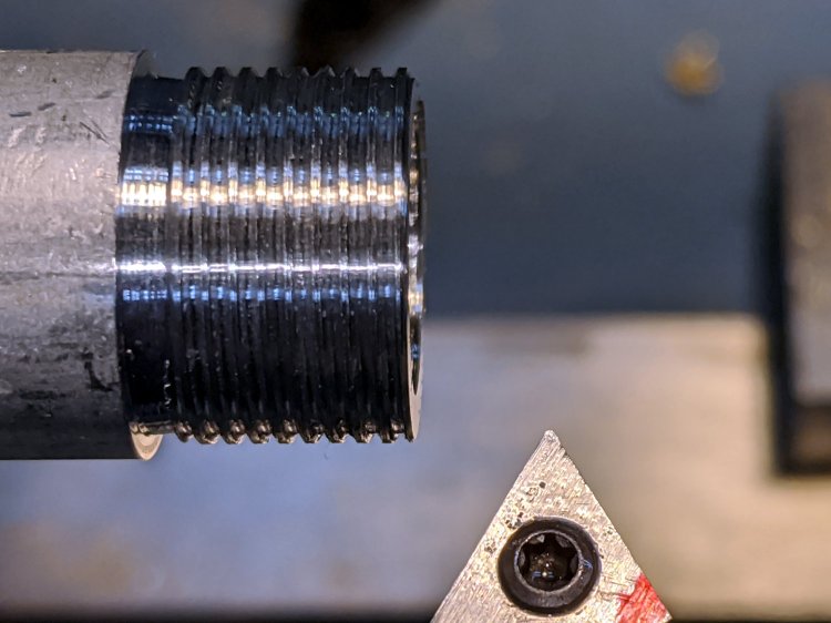
Close the chuck jaws and shove them flush with the surface:
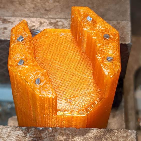
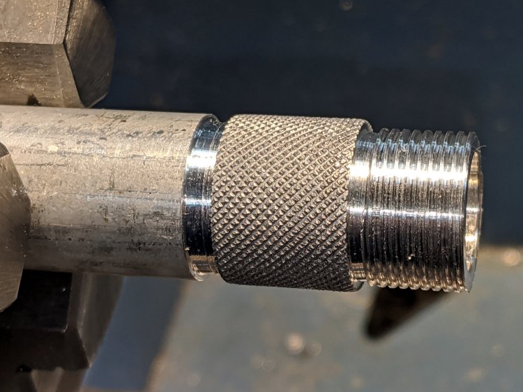
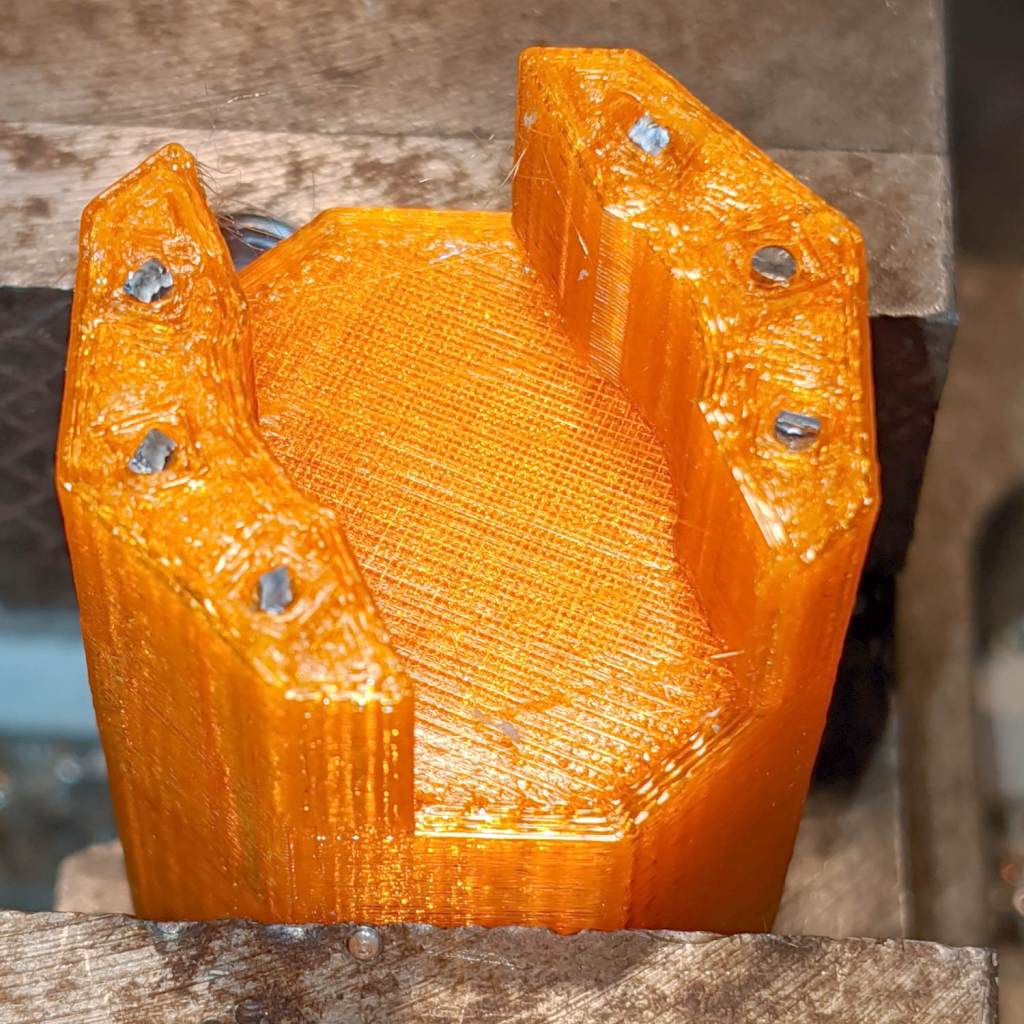
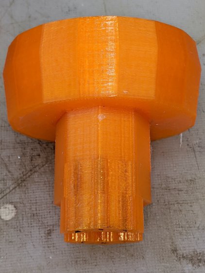
You can see the pins and their solid plastic shells through the wrench stem:
Early testing shows the reinforced wrench works just as well as the previous version, even on some new valves sporting different handles, with an equally sloppy fit for all. No surprise: I just poked holes in the existing model and left all the other dimensions alone.
The OpenSCAD source code as a GitHub Gist:
| // Hose connector knob | |
| // Ed Nisley KE4ZNU – June 2015 | |
| // 2020-05 add reinforcing rods | |
| Layout = "Build"; // [Knob, Stem, Show, Build] | |
| RodHoles = true; | |
| //- Extrusion parameters – must match reality! | |
| /* [Hidden] */ | |
| ThreadThick = 0.25; | |
| ThreadWidth = 0.40; | |
| function IntegerMultiple(Size,Unit) = Unit * ceil(Size / Unit); | |
| Protrusion = 0.1; | |
| HoleWindage = 0.2; | |
| //—— | |
| // Dimensions | |
| /* [Dimensions] */ | |
| RodOD = 1.6; | |
| RodAngle = 35; | |
| /* [Hidden] */ | |
| StemOD = 30.0; // max OD for valve-to-valve clearance | |
| BossOD = 16.0; // single-ended handle boss | |
| SlotWidth = 13.0; | |
| SlotHeight = 10.0; | |
| StemInset = 10.0; | |
| StemLength = StemInset + SlotHeight + 25.0; | |
| StemSides = 2*4; | |
| Align = 0*180/StemSides; // 1* produces thinner jaw ends | |
| KnobOD1 = 70; // maximum dia without chamfer | |
| KnobOD2 = 60; // top dia | |
| KnobSides = 4*4; | |
| DomeHeight = 12; // dome shape above lobes | |
| KnobHeight = DomeHeight + 2*SlotHeight; | |
| DomeOD = KnobOD2 + (KnobOD1 – KnobOD2)*(DomeHeight/KnobHeight); | |
| DomeArcRad = (pow(KnobHeight,2) + pow(DomeOD,2)/4) / (2*DomeHeight); | |
| RodBCD = (StemOD + BossOD)/2; | |
| //- Adjust hole diameter to make the size come out right | |
| module PolyCyl(Dia,Height,ForceSides=0) { // based on nophead's polyholes | |
| Sides = (ForceSides != 0) ? ForceSides : (ceil(Dia) + 2); | |
| FixDia = Dia / cos(180/Sides); | |
| cylinder(r=(FixDia + HoleWindage)/2,h=Height,$fn=Sides); | |
| } | |
| //– Stem for valve handles | |
| module Stem() { | |
| difference() { | |
| rotate(Align) | |
| cylinder(d=StemOD,h=StemLength,$fn=StemSides); | |
| translate([0,0,SlotHeight/2 – Protrusion/2]) | |
| cube([2*StemOD,SlotWidth,(SlotHeight + Protrusion)],center=true); | |
| translate([0,0,-Protrusion]) | |
| cylinder(d=BossOD,h=SlotHeight,$fn=2*StemSides); | |
| if (RodHoles) | |
| for (i=[-1:1]) | |
| rotate(i*RodAngle + 90) | |
| for (j=[-1,1]) | |
| translate([j*RodBCD/2,0,-Protrusion]) | |
| rotate(180/4) | |
| PolyCyl(RodOD,2*SlotHeight,4); | |
| } | |
| } | |
| //– Hand-friendly knob | |
| module KnobCap() { | |
| difference() { | |
| scale([1.0,0.75,1.0]) | |
| rotate(180/KnobSides) | |
| intersection() { | |
| translate([0,0,(KnobHeight-DomeArcRad)]) | |
| sphere(r=DomeArcRad,$fa=180/KnobSides); | |
| cylinder(r1=KnobOD1/2,r2=KnobOD2/2,h=KnobHeight,$fn=KnobSides); | |
| cylinder(r1=KnobOD2/2,r2=KnobOD1/2,h=KnobHeight,$fn=KnobSides); | |
| } | |
| translate([0,0,-Protrusion]) | |
| rotate(Align) | |
| cylinder(d=(StemOD + 2*ThreadWidth),h=(StemInset + Protrusion),$fn=StemSides); | |
| } | |
| } | |
| //- Build it | |
| if (Layout == "Knob") | |
| KnobCap(); | |
| if (Layout == "Stem") | |
| Stem(); | |
| if (Layout == "Build") { | |
| translate([-KnobOD1/2,0,0]) | |
| KnobCap(); | |
| translate([StemOD/2,0,StemLength]) | |
| rotate([180,0,0]) | |
| Stem(); | |
| } | |
| if (Layout == "Show") { | |
| translate([0,0,0]) | |
| Stem(); | |
| translate([0,0,StemLength – StemInset]) | |
| KnobCap(); | |
| } |