Ed Nisley's Blog: Shop notes, electronics, firmware, machinery, 3D printing, laser cuttery, and curiosities. Contents: 100% human thinking, 0% AI slop.
Tag: Improvements
Making the world a better place, one piece at a time
Just for completeness, here’s what the various soaker hose clamps look like in the garden, as solid models only let you visualize the ideal situation:
Soaker Hose Connector Clamp – Show view
This one prevents a puddle in the path to the right:
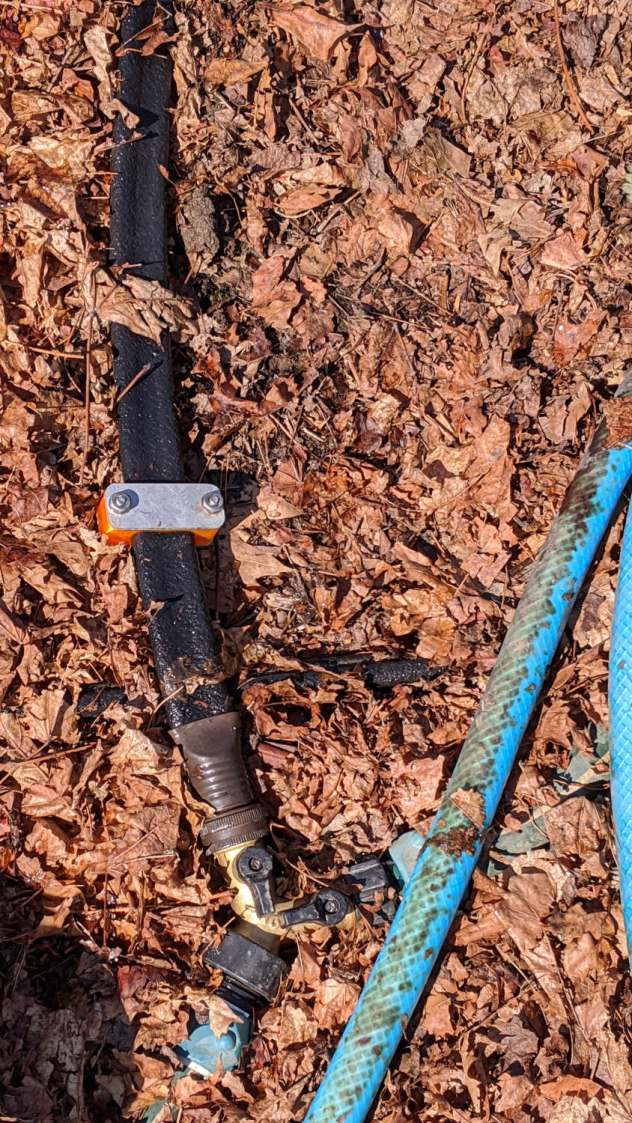
Soaker hose repairs in situ – clamp
Bending the hoses around the end of a bed puts them on edge, with this clamp suppressing a shin-soaking spray to the left:
Soaker hose repairs in situ – end-on clamp
The clamp at the connector closes a leak around the crimped brass fitting, with the other two preventing gouges from direct sprays into the path along the bottom of the picture:
Soaker hose repairs in situ – clamps and connector fix
All in all, a definite UI improvement!
As far as I can tell, we have the only soaker hose repairs & spritz stoppers in existence. Hooray for 3D printing!
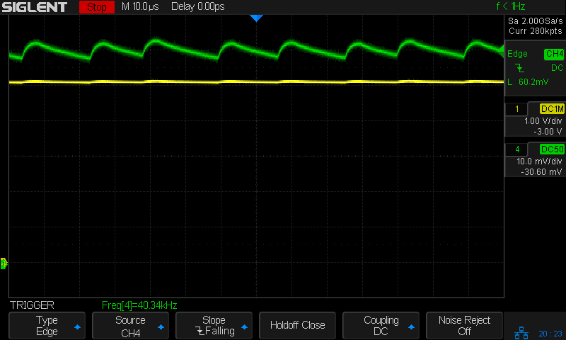
The voltage (yellow) and current (green, 100 mA/div) waveforms look downright tame compared to some of the other chargers!
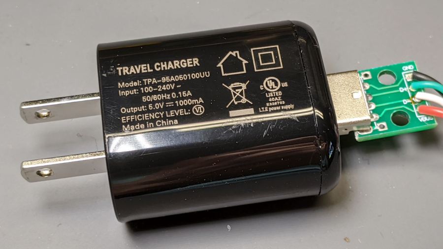
I made a cursory attempt to crack the case open, but gave up before doing any permanent damage. Hey, that UL listing (and, presumably, the interior details) means they’re three times the price of those Anonymous chargers!
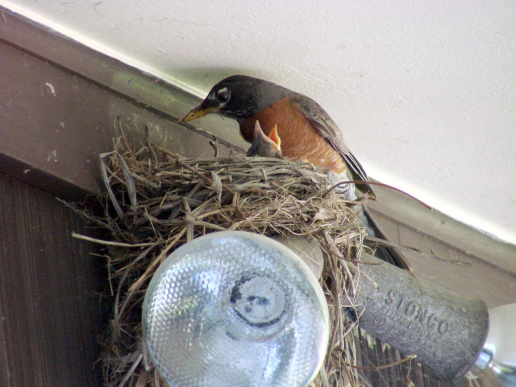
Nothing prizewinning, but better than no picture at all:
Garage Robin – recovered image
Note that you start by copying a reasonable chunk of the partition from the Memory Stick / (micro)SD Card first, to prevent a bad situation from getting worse.
Now I can remember the easy way the next time around this block …
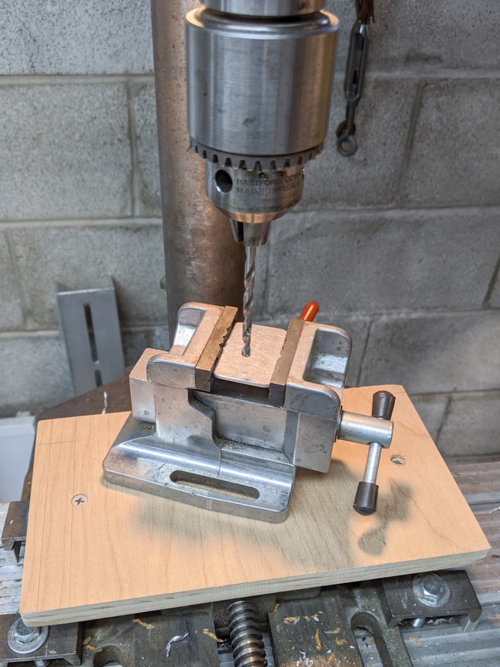
I built a small plywood work table for the drill press:
Drill press – scarred vise table
Obviously, that was a long time ago. It’s a plywood scrap with a small cleat screwed to its bottom, upon which one can position / clamp / hold / finagle smallish workpieces without worrying about drilling into the surface.
The mill vise under the plywood grips the cleat and the whole affair rides on a Sears “Drill Press Milling Attachment Stock No 27585” which is basically a simple XY table with hand dials. It’s not rigid enough for actual milling (which you should never do on a drill press, anyway, because the end mill will pull itself out of the Jacobs chuck), but it’s good for tweaking the position before you drill something.
One should never hand-hold workpieces while drilling.
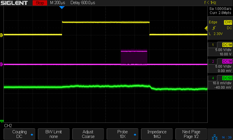
So I can see the actual current waveform of a Glass Tile box running from a bench power supply:
Tiles 2×2 – bench supply – 50 mA-div
The top trace is the firmware heartbeat from the Arduino Nano, the middle trace is the SK6812 LED data stream, and the bottom trace is the USB current at 50 mA/div. The current steps downward by about 10 mA (just after the data burst) when one of the tiles changes color and and LED shuts off.
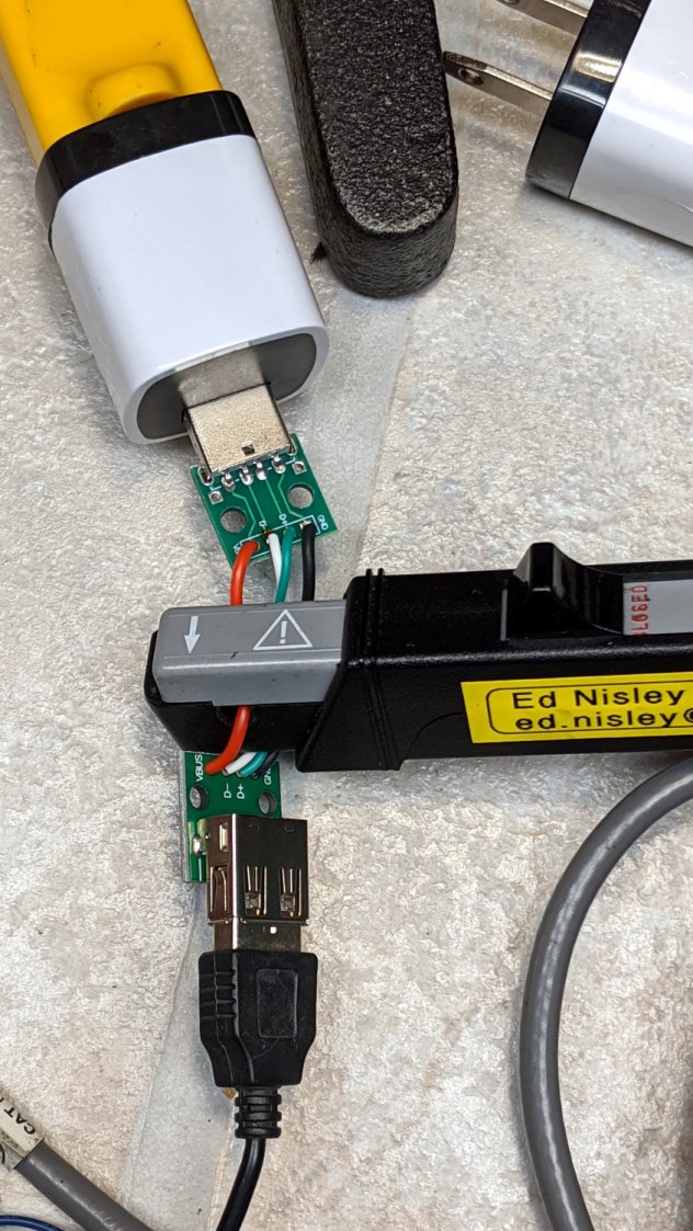
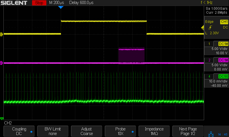
The current probe reveals some mysteries, such as this waveform from a dirt-cheap USB charger:
Tiles 2×2 – anon white charger – 50 mA-div
I wonder why it’s ramming 100 mA current spikes into the circuit, too. At least now I can see what’s going on.
I’ve been putting this type of support structure inside screw holes & suchlike for years:
Browning Hi-Power Magazine Block – solid model – Generic 1 – support detail
It’s basically a group of small rectangles rotated around the hole’s axis and about one thread thickness shorter than the overhanging interior.
I’ve found that incorporating exactly the right support structure eliminates Slic3r’s weird growths, eases removal, and generally works better all around.
So doing this for the baseplate of the Glass Tile frame came naturally:
Glass Tile Frame – octagonal support
This OpenSCAD snippet plunks one of those asterisks in each of four screw holes:
  if (Support)
    color("Yellow")
      for (i=[-1,1], j=[-1,1])
        translate([i*InsertOC.x/2,j*InsertOC.y/2,0])
          for (a=[0:45:135])
              rotate(a)
                translate([0,0,(Screw[LENGTH] - ThreadThick)/2])
                  cube([Screw[OD] - 2*ThreadWidth,2*ThreadWidth,Screw[LENGTH] - ThreadThick],center=true);
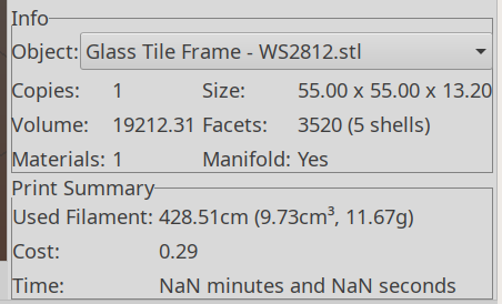
The “cubes” overlap in the middle, with no completely coincident faces or common edges, so it’s 2-manifold. Slic3r, however, produces a weird time estimate whenever the model includes those structures:
Slic3r – NaN time estimate
NaN stands for Not A Number and means something horrible has happened in the G-Code generation. Fortunately, the G-Code worked perfectly and produced the desired result, but I’m always uneasy when Something Seems Wrong.
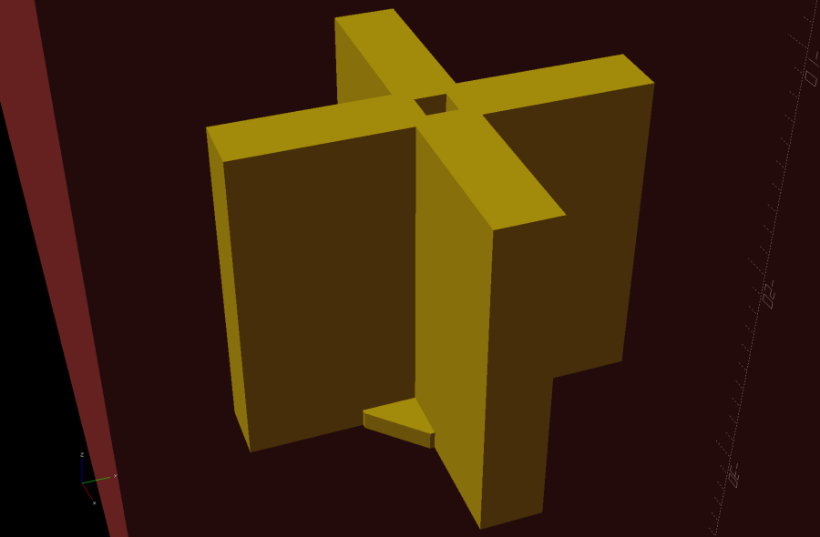
Messing around with the code produced a slightly different support structure:
Glass Tile Frame – quad support
The one thread thick square on the bottom helps glue the structure to the platform and four ribs work just as well as eight in the octagonal hole:
  Fin = [Screw[OD]/2 - 1.5*ThreadWidth,2*ThreadWidth,ScrewRecess - ThreadThick];
  if (Inserts && SupportInserts)
    color("Yellow")
      for (i=[-1,1], j=[-1,1])
        translate([i*InsertOC.x/2,j*InsertOC.y/2,0]) {
          rotate(180/8)
            cylinder(d=6*ThreadWidth,h=ThreadThick,$fn=8);
          for (a=[0:90:360])
              rotate(a)
                translate([Fin.x/2 + ThreadWidth/2,0,(ScrewRecess - ThreadThick)/2])
                  cube(Fin,center=true);
        }
Which changed the NaN time estimates into actual numbers.
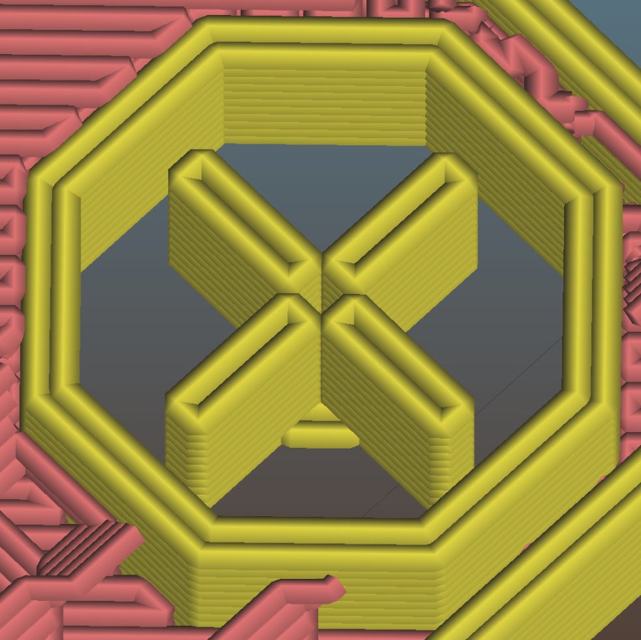
One key difference may be the small hole in the middle. The four ribs (not two!) now overlap by one thread width around the hole, so they’re not quite coincident and Slic3r produces a tidy model:
Glass Tile Frame – quad support – Slic3r
The hole eliminates a smear of infill from the center, which may have something to do with the improvement.
In any event, I have an improved copypasta recipe for the next screw holes in need of support, even if I don’t understand why it’s better.