Ed Nisley's Blog: Shop notes, electronics, firmware, machinery, 3D printing, laser cuttery, and curiosities. Contents: 100% human thinking, 0% AI slop.
Tag: Improvements
Making the world a better place, one piece at a time
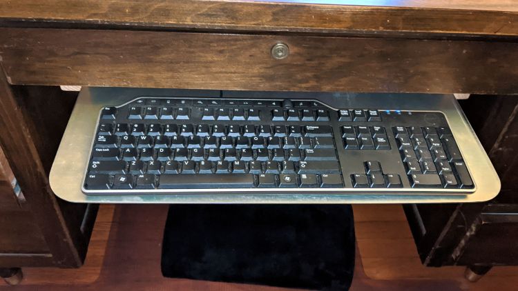
Long ago and far away, I moved the keyboards off our desk surfaces to a more convenient location on a tray under the middle drawer. Mary’s desk recently gained a somewhat thinner keyboard with a thumbwheel volume control, so she wanted the tray moved up:
Keyboard Tray Relocation – in place
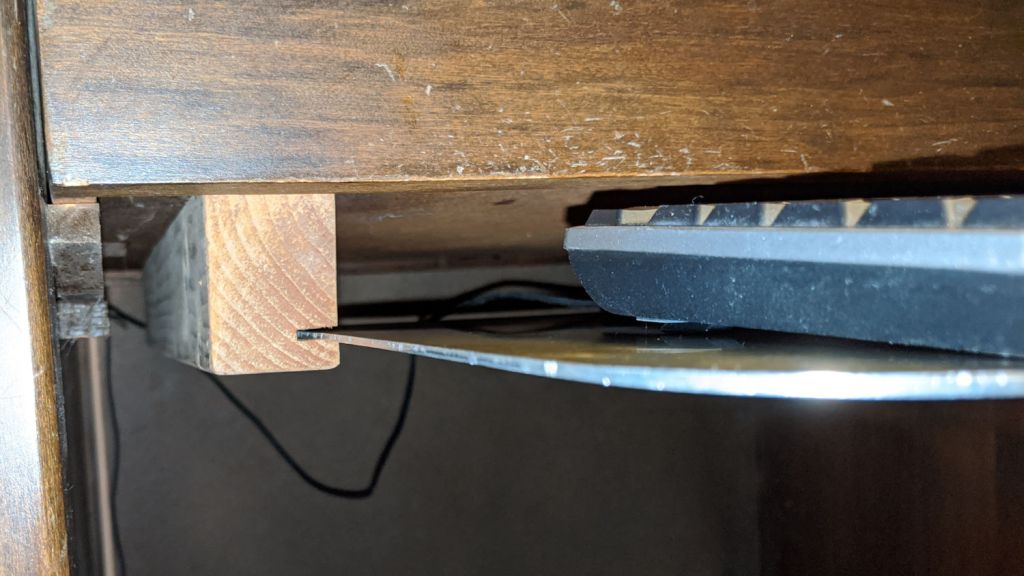
The supports on either side started out as 2×4 lumber with a slot cut (using the radial arm saw I no longer have) for the aluminum sheet:
Keyboard Tray Relocation – support view
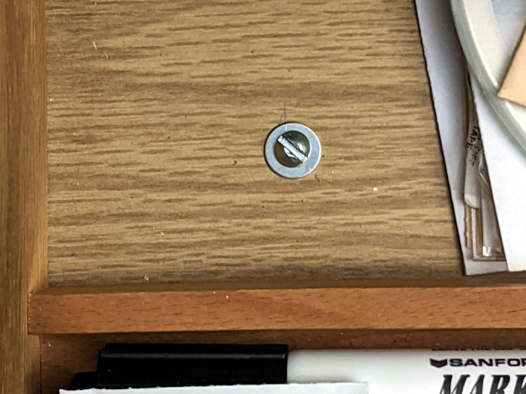
For the record, a pair of screws hold each support to the drawer:
Keyboard Tray Relocation – support screw
Not elegant. Works fine. Good enough!
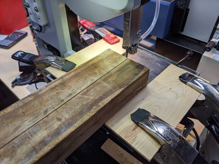
Tiny Bandsaw™ wasn’t designed for ripsawing lumber, but the same Proxxon 10/14 TPI blade I use for aluminum worked better than I expected to lop a 1-¼ inch strip from the wood slats:
Keyboard Tray Relocation – bandsaw fixture
That’s a reenactment based on a true story. The wood scraps clamped on the bandsaw table leave enough clearance for the 2×4 slide to freely, yet not enough for the blade to wander off track.
You can tell how long ago I built the original trays: nary a trace of 3D printing!
Well, it’s really zucchini bread season, with grated nutmeg among the spices (*):
Zucchini bread – minus QC sample
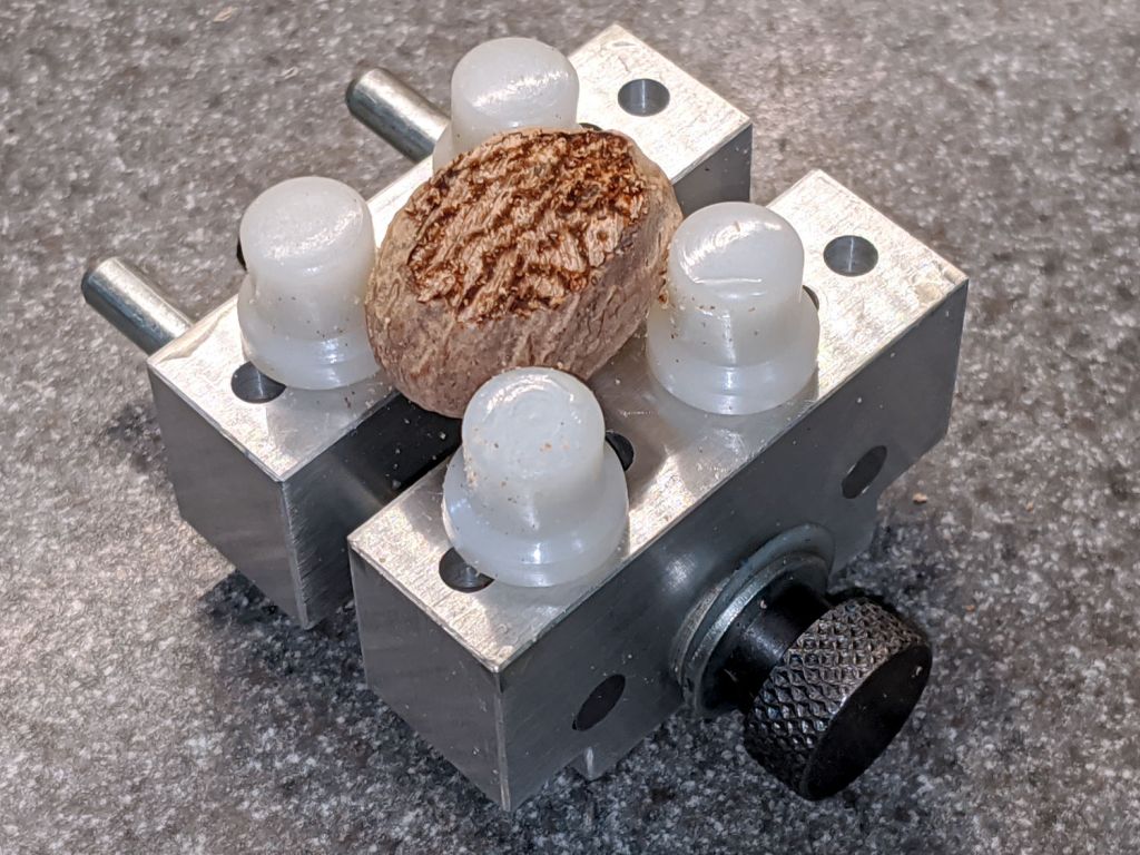
Having recently bought a very sharp grater, I hauled out a small vise to save my fingertips:
Nutmeg grating – mini-vise
The dark lunette comes from a previous clamping attempt; it takes a while to find the most secure pin arrangement.
Grate a flat:
Nutmeg grating – first flat
I’ve always enjoyed the surprisingly intricate patterns inside what looks like a bland nut.
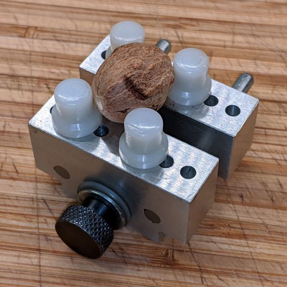
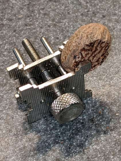
Flip it over, flatten the other side, and grab it in an even smaller vise:
Nutmeg grating – flat clamping
In truth, that vise is intended for small cylinders, not flattened nuts, but I figured it’d suffice for light-duty use. Grate parallel to the vise screw, reclamp as needed, and it worked out reasonably well.
Eventually, you have a pile of powder and one cubic nutmeg:
Nutmeg grating – results
I’m sure there’s a way to grate the remaining cube, but I’m unwilling to shred my fingertips.
Tip the powder into a small jar and repeat as needed. Each nutmeg produces about 5 grams and I did three of the things this time.
Yummy!
(*) We omit the cloves and knock the sugar down by half. Your tastes will surely differ.
However, it’s worth noting my original, butt-ugly Az-El mounts lasted for all of those nine years, admittedly with adjustments along the way, which is far more than the commercial mountsmaking me unhappy enough to scratch my itch.
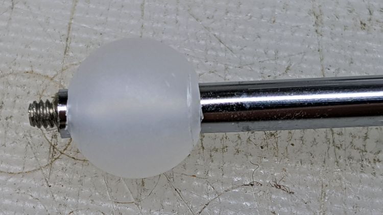
Scaling it down for a 10 mm polypropylene ball around the base of the 30 mm inspection mirror’s shaft simplified everything:
Helmet Mirror Ball Mount – drilled ball test
I’m reasonably sure I couldn’t have bought 100 polypro balls for eight bucks a decade ago, but we’ll never know. Drilling the hole was a complete botch job, about which more later. The shaft came from a spare mirror mount I made up a while ago; a new shaft appears below.
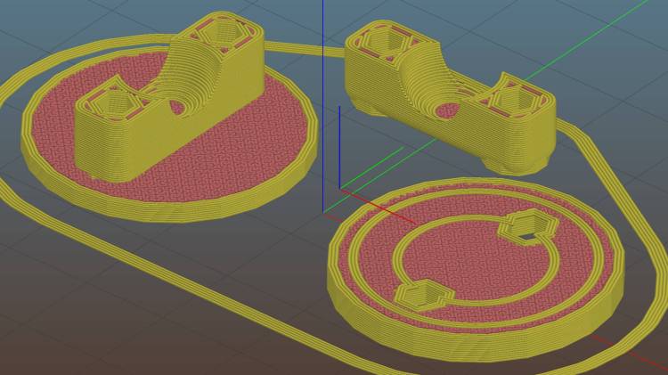
The solid model, like Gaul, is in three parts divided:
Helmet Mirror Ball Mount – Slic3r
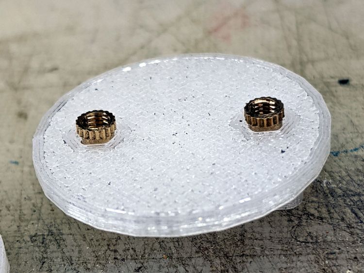
The helmet plate (on the right) has a slight indent more-or-less matching the helmet curvature and gets a layer of good double-stick foam tape. The clamp base (on the left) has a pair of brass inserts epoxied into matching recesses below the M3 clearance holes:
Helmet Mirror Ball Mount – inserts
A layer of epoxy then sticks the helmet plate in place, with the inserts providing positive alignment:
Helmet Mirror Ball Mount – plates
The clamp screws pull the inserts against the plastic in the clamp base, so they can’t pull out or through, and the plates give the epoxy enough bonding surface that (I’m pretty sure) they won’t ever come apart.
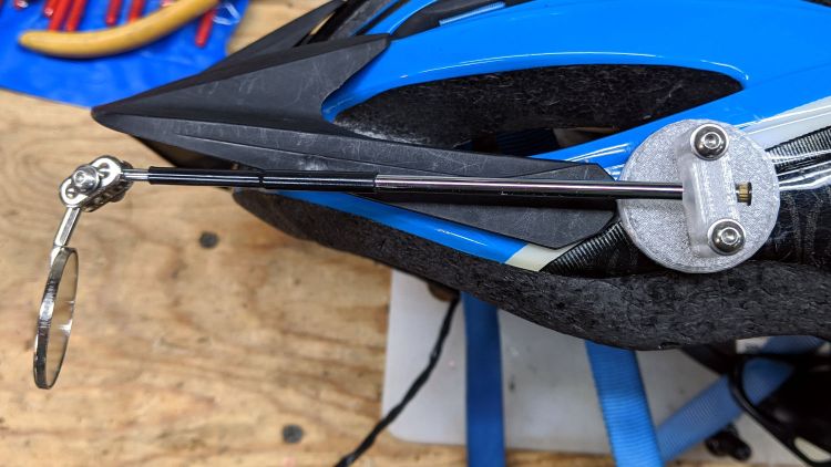
I turned down a 2 mm brass insert to fit inside the butt end of the mirror shaft and topped it off with a random screw harvested from a dead hard drive:
Helmet Mirror Ball Mount – assembled – rear view
At the start, it wasn’t obvious the shaft would stay stuck in the ball, so I figured making it impossible to pull out would eliminate the need to find it by the side of the road. As things turned out, the clamp exerts enough force to ensure the shaft ain’t goin’ nowhere, so I’ll plug future shafts with epoxy.
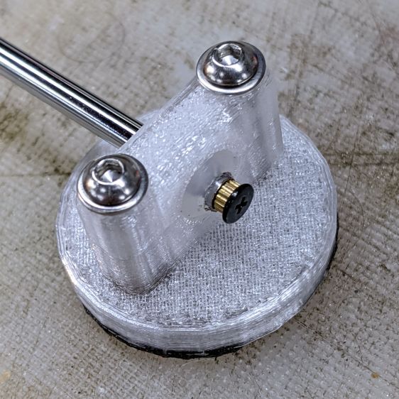
The front side of the clamp looks downright sleek:
Helmet Mirror Ball Mount – assembled – front view
Well, how about “chunky”?
The weird gray-black highlights are optical effects from clear / natural PETG, rather than embedded grunge; it looks better in person. I should have used retina-burn orange or stylin’ black.
This mount is much smaller than the old one and should, in the event of a crash, not cause much injury. Based on how the running light clamp fractures, I expect the clamp will simply tear out of the base on impact. In the last decade, neither of us has crashed, so I don’t know what the old mount would do.
The clamp is 7 mm thick (front-to-back), set by the M3 washer diameter, with 1.5 mm of ball sticking out on each side. The model has a kerf one thread high (0.25 mm) between the pieces to add clamping force and, with the screws tightened down, moving the ball requires a disturbingly large effort. I added a touch of rosin and that ball straight-up won’t move, which probably means the shaft will bend upon droppage; I have several spare mirrors in stock.
On the other paw, the ball turns smoothly in the clamp and it’s easy to position the shaft as needed: much better than the old Az-El mount!
The inspection mirror hangs from a double ball joint which arrives with a crappy screw + nut. I epoxied the old mirror mount nut in place, but this time around I drilled the plates for a 3 mm stainless SHCS, used a wave washer for a bit of flexible force, and topped it off with a nyloc nut:
Helmet Mirror Ball Mount – mirror joint
I’m unhappy with how it looks and don’t like how the washer hangs in free space between those bumps, so I may eventually turn little brass fittings to even things out. It’s either that or more epoxy.
So far, though, it’s working pretty well and both units meet customer requirements.
This file contains hidden or bidirectional Unicode text that may be interpreted or compiled differently than what appears below. To review, open the file in an editor that reveals hidden Unicode characters.
Learn more about bidirectional Unicode characters
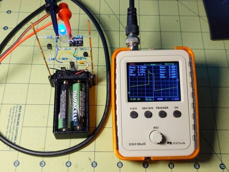
With a pair of fresh AA alkaline cells producing 3.1 V (not the NiMH Duracells you see in the picture), the blue LED blinks brightly.
The 610 mV peak voltage across R1 shows the LED starts at 25.4 mA:
LM3909 blue – 3.1 V – R1 24 ohm
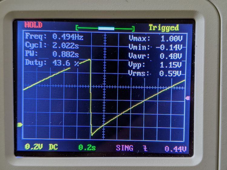
The capacitor reaches 1 V, then goes about 150 mV into reverse charge during the flash (note the different horizontal scales):
LM3909 blue – 3.1 V – C1 V
The Darlington version of Q1 seems to do a decent job of keeping the cap out of reverse charge. A Shottky diode would add a few hundred mV, but I doubt there’s anything nasty going on inside the cap as it stands.
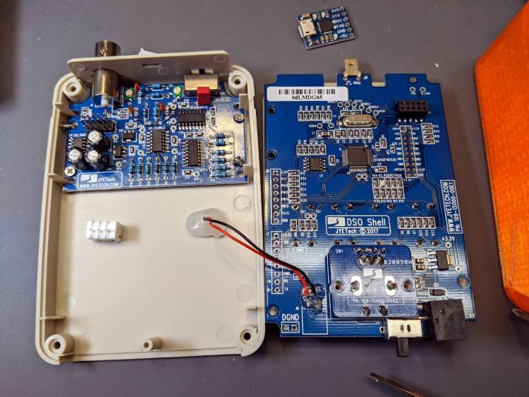
Taking all those pictures of the DSO150 screen reminded me it has a data dump function: press the V/Div and ADJ buttons to squirt configuration, measurements, and trace data from the TX pad on the main board, just in front of the red-black power wires hot-melt glued in place:
DSO150 USB serial adapter – interior
The picture shows the “before” stage, while I was figuring out where to carve another hole in the case.
NB: The 113-15001-111 DSO150 firmware version includes the serial output option, so you won’t need third-party firmware. Similarly, current PCBs bring the serial pins to neatly labeled header pads. You should refer to the JYETech DSO150 / DSO Shell product page for the details.
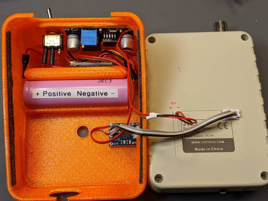
After all the cuttin’ and filin’ was done, it looked like this:
DSO150 USB serial adapter – exterior
The power switch on the back of the case (top of the picture) disconnects the lithium cell from the charge controller board (now tucked behind the battery) to eliminate any trickle current discharge. Charging the battery thus requires turning that switch on and turning the scope off with its own power switch (along its front edge). Capturing trace data requires having both switches on (duh), whereupon the scope’s normal operating current convinces the charge controller that the cell hasn’t reached full charge. Turn the scope off and, most likely, the controller will tell you the cell is fully charged.
An intro blurb squirts from the port at 115200 in good old 8N1 format when you turn the scope on:
It’s all in neatly comma-separated-value format, so you can slam it into a spreadsheet and have your way with it. Utilities also exist to capture the data, extract the values, and send them directly to GNUplot, etc.
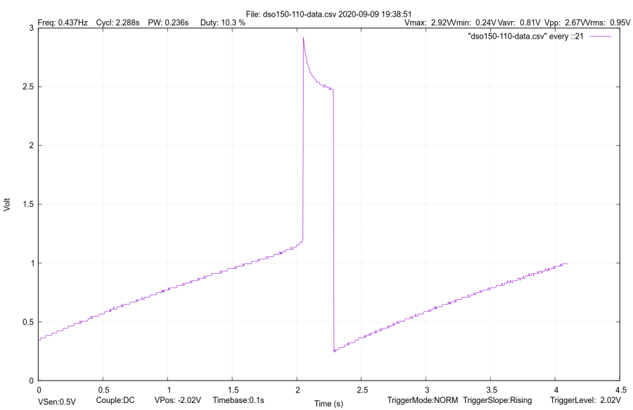
Like so:
DSO150 test image
If I expected to do a lot of that, I’d boldify the traces and embiggen the text, all of which is in the nature of fine tuning.
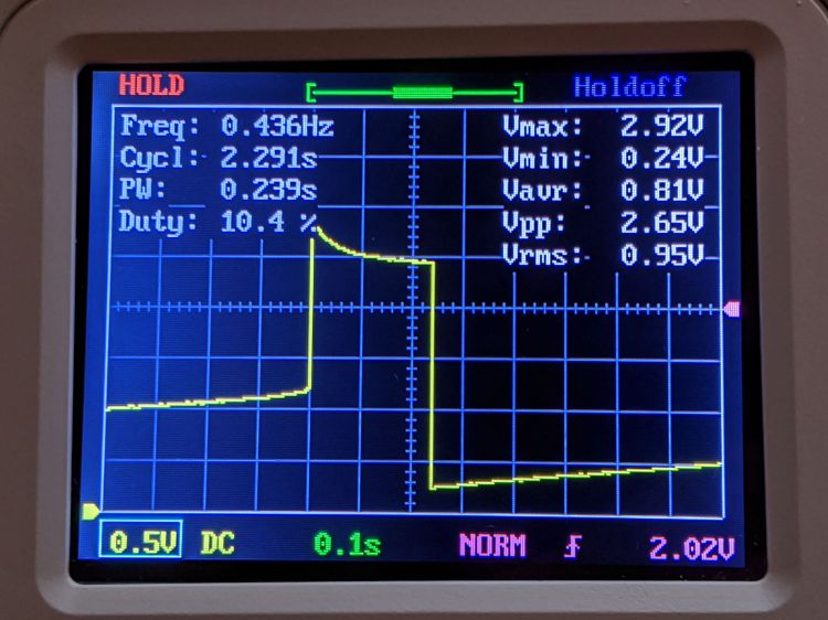
It’s hard to reproduce the beauty of the DSO150’s display, though:
DSO150 test image
The DSO150 remains pretty good for being the worst oscilloscope I’m willing to use …
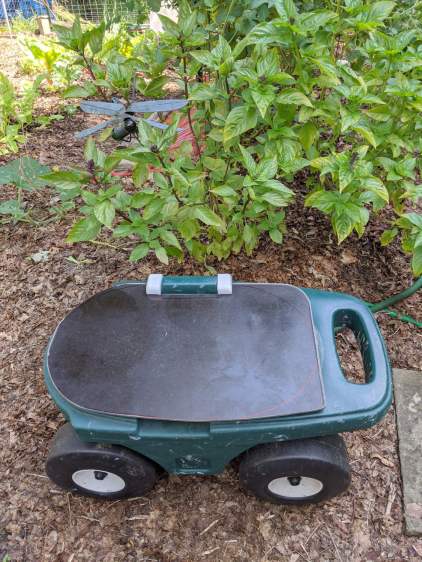
As expected, the plywood seat I put on the Step2 Garden Seat for Mary’s Vassar Farms plot lasted about a year before the wood rotted away around the screws. In the meantime, we’d acquired a stack of SiLite cafeteria trays, so we applied one to the cause of better seating:
Step2 Seat – tray variant
Various eBay listings value that slab of BakeliteMelamine up to $20, which is far more than Mary paid for the entire stack at a local tag sale. They also call that color “rich brown”, which is certainly better than what immediately came to mind when I saw them.
The stylin’ asymmetric design happened when I realized the squared-off handle end of the cart didn’t demand a rounded-off end of the seat. I cut off the raised tray rim before sketching the rounded outline using the rotted seat as a template; some of the sketch remains over on the right-front corner. A session with Mr Belt Sander put the remaining rim edges flush with the surface, no matter what the picture suggests.
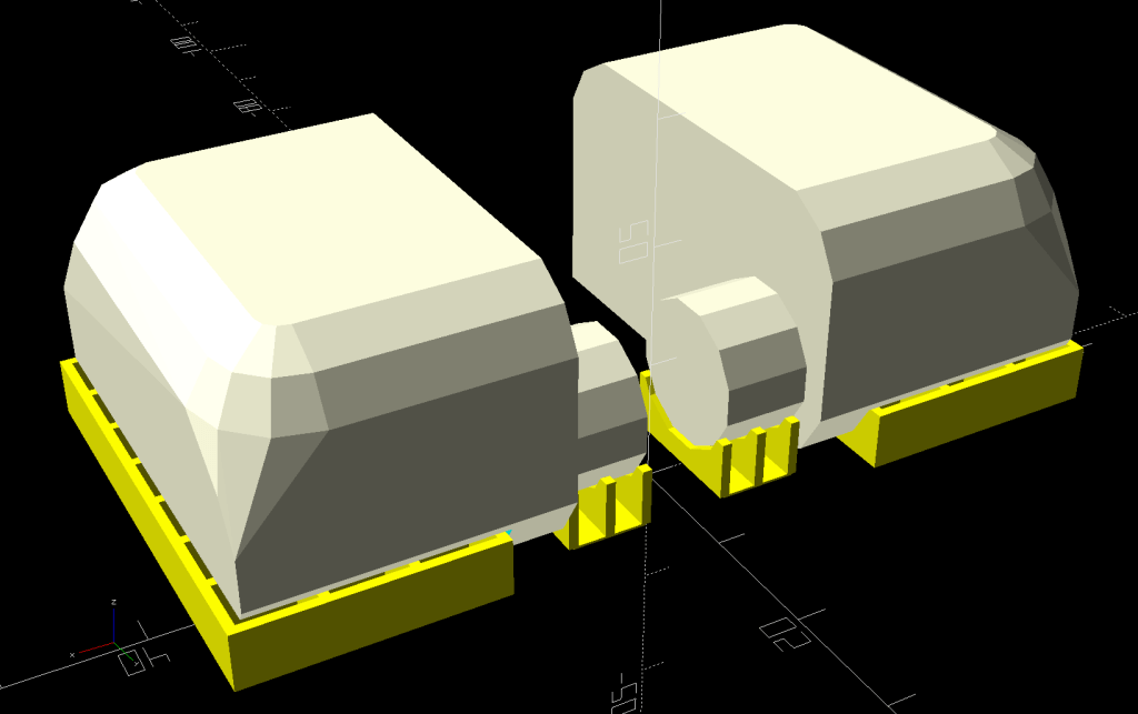
The tray being 2 mm thinner than the plywood, I tried printing the hinges in a different orientation with different built-in support:
Rolling Cart Hinges – solid model – build
The perimeter threads pulled up far too much and, although fiddling with cooling would likely help, I think the original orientation was better:
Rolling Cart Hinges – solid model – bottom
Given that the post-apocalypse breakfast will be served on similar trays, the seat should survive for quite a while in the garden. We think the sun will convert the brown surface into a bun warmer; a coat of white paint may be in its future.
The original OpenSCAD code is still out there as a GitHub Gist.
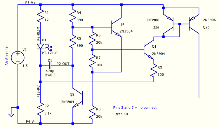
The LM3909 IC boosted a single 1.5 V cell enough to fire a red(-ish) LED, even with the cell well under 1 V. I want to blink a blue(-ish) LED from a pair of AA alkaline cells (with the right size & heft to serve as a base for the hairball circuitry), so the voltage ranges from just over 3 V down to maybe 1.5 V. Although the original circuit works, the LED pulse is long enough to put a reverse bias on the timing capacitor; a 470 µF electrolytic cap (positive terminal on the right at node P2-OUT) produces a pulse every few seconds.
A slightly tweaked version of the circuitry puts -400 mV across C1 (green trace) by the end of the pulse:
Discrete LM3909 – basic circuit – 3.0 V simulation
The App Note describes the negative feedback loop from the collector of “power transistor” Q3 through Q4 and Q1, closing through the Q2 current mirror. The base-emitter drops of Q4 and Q1 set the trip point where Q1 starts to conduct and the LED turns on.
Q3 is on when the LED is on, with C1 reverse-charging through R1 and the LED. The voltage at the top of R2 rises from the negative voltage at the start of the pulse, carrying the emitter of Q1 along with it. The LED pulse will end when the rising emitter voltage shuts off Q1 and, thus, the Q2 current mirror driving Q3. Because Q3 holds the bottom of R5 close to 0 V, the base of Q4 is at about half the supply voltage, so Q1 remains on until its emitter rises to about 2 forward drops (handwavingly ignoring the R6 + R7 voltage divider) below the supply.
If the LED pulse is longer than required to completely discharge C1, the poor cap gets reverse-biased and suffers indigestion. Aluminum electrolytics can withstand a little reverse bias, but it’s Bad Practice.
When Q3 and the LED are off, C1 forward-charges through (R4 + R5) + R2, with most of the initial voltage across R2, because C1 should start with a little more than 0 V across it. This holds the current mirror off until C1 charges enough to raise the base of Q4 about two forward drops above Q1’s emitter, shove current through Q4 and Q1, turn on the Q2 current mirror, Q3, and light the LED.
Around and around it goes!
The worst case for reverse charge happens at higher supply (a.k.a. battery) voltages and higher LED currents. Reducing the reverse charge time requires more forward drop through Q4 + Q1 to soak up the higher voltage and lower the trip voltage at Q1’s emitter, which suggests putting another forward-biased junction in series.
Putting a diode in Q1’s base lead doesn’t produce much improvement:
Discrete LM3909 – Q1 B diode – 3.0 V
Perhaps because the 27 µA current at the trip point is so low the diode doesn’t actually have much forward drop; the simulation says 400 mV.
Putting the diode in the emitter runs the current mirror’s 5 mA through it:
Discrete LM3909 – Q1 E diode – 3.0 V
The overall period remains about 2 s, but the LED pulse = reverse charge time drops by a factor of two and the cap voltage bottoms out at 0 V, so that’s good.
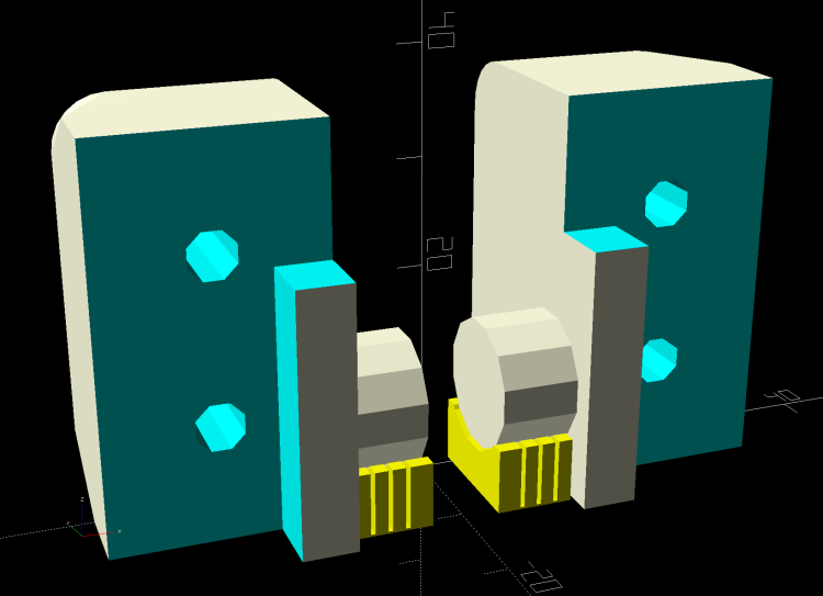
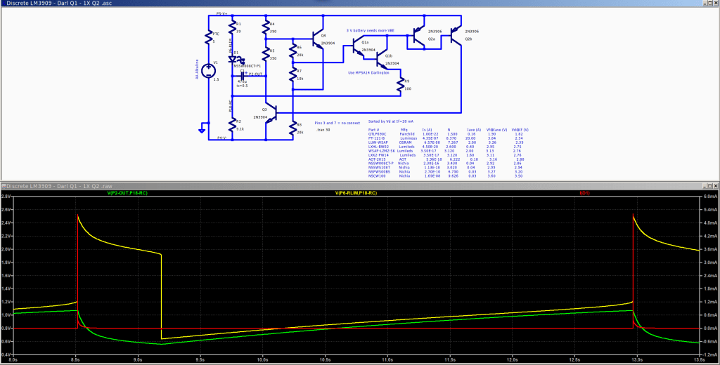
A Darlington transistor provides far more gain to compensate for the reduced base drive:
Discrete LM3909 – Darl Q1 – 3.0 V
The LED pulse is slightly shorter and its current goes up a smidge, but the cap voltage remains above zero.
A line in the LM3909 App Note mentions that the Q2 current mirror amplifies Q1’s emitter current by a factor of three: “This current will be amplified by about 3 by Q2 and passed to the base of Q3”. An IC current mirror’s designer can scale its output by varying the collector area, but out here in the discrete world we must splice multiple transistors in parallel:
Discrete LM3909 – Darl Q1 3xQ2- 3.0 V
More base drive in Q3 doesn’t buy much, because it’s already pretty well saturated during the pulse, but the current goes up enough to push C1 slightly into reverse charge territory again. As far as I can tell, the factor-of-three gain was required to make up for the relatively poor performance of IC technology around 1970; things have definitely improved since then.
It’s worth mentioning that the actual circuitry (in particular, the LEDs!) will differ from the simulations, so the pretty plots are more along the lines of serving suggestions than actual predictions. Verily, a simulation can’t prove that a circuit will work, but can sometimes help show why it won’t.
All the LTSpice simulation files tucked into a GitHub Gist:
This file contains hidden or bidirectional Unicode text that may be interpreted or compiled differently than what appears below. To review, open the file in an editor that reveals hidden Unicode characters.
Learn more about bidirectional Unicode characters
This file contains hidden or bidirectional Unicode text that may be interpreted or compiled differently than what appears below. To review, open the file in an editor that reveals hidden Unicode characters.
Learn more about bidirectional Unicode characters
This file contains hidden or bidirectional Unicode text that may be interpreted or compiled differently than what appears below. To review, open the file in an editor that reveals hidden Unicode characters.
Learn more about bidirectional Unicode characters
This file contains hidden or bidirectional Unicode text that may be interpreted or compiled differently than what appears below. To review, open the file in an editor that reveals hidden Unicode characters.
Learn more about bidirectional Unicode characters
This file contains hidden or bidirectional Unicode text that may be interpreted or compiled differently than what appears below. To review, open the file in an editor that reveals hidden Unicode characters.
Learn more about bidirectional Unicode characters