I’ve been using not-dead-yet lithium batteries to power astable multivibrators blinking LEDs on the red-to-yellow end of the spectrum, because the over-discharge protection circuitry in the batteries shuts down at 2.5 V, while not eking much light from LEDs toward the blue end of the spectrum.
Back in the late 60s, when integrated circuits were new, National Semiconductor designed and, in the early 70s, introduced the LM3909: “a monolithic oscillator specifically designed to flash Light Emitting Diodes”. The IC used an electrolytic capacitor as both timing element and voltage booster by charging the cap, then switching it in reverse series with the LED, to produce a voltage drop larger than the 1.5 V battery supply. The original National Semiconductor LM3909 datasheet will get you started and Application Note 154 gives more details and insight.
Rob Paisley’s work from 2008 suggested a discrete-transistor version might look just as attractive, in a techie sort of way, as the astables, and perhaps boost the 2 V from a pair of not-dead-yet alkaline cells high enough to light a blue LED.
Some LTSpice twiddling produces a suitable circuit:
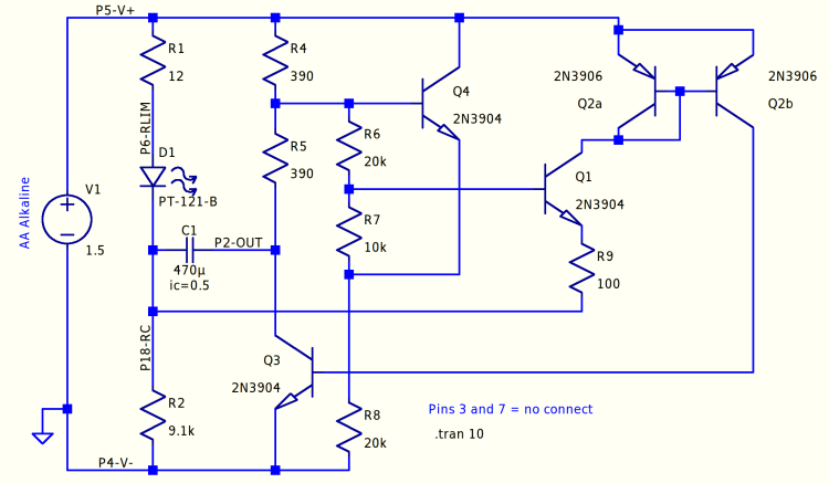
The labeled nodes correspond to pin numbers on the IC package, with a suffix indicating what they did for a living. R2 combines the two timing resistors in the IC into a single unit, so “P18-RC” combines the pins. The Q2 pair over on the right forms a current mirror driving Q3, which the doc calls the “power transistor”, to yank the positive end of the capacitor to ground to light the LED.
The LED is faked by a PT-121-B diode with a 2.34 V forward drop at 20 mA. It’s rated for 20 A average current, so it’s not a particularly good model for a piddly 5 mm LED, but I’ll define it to be Good Enough for now.
Running the simulation at 1.5 V is encouraging:

The green trace gives the voltage across the capacitor. Under these conditions, the voltage stays positive, although not by much.
Running it from a 3 V supply changes the results:

The cap charges to about the same voltage, but the pulse now lasts long enough to charge it nearly half a volt in the wrong direction. This is Bad Practice, even though my similarly offending astables have been doing it for years.
The data sheet points out that the forward drops of Q1 and Q2 determine the trigger level for the start of the LED pulse, so adding another forward-biased junction in series should let the cap charge to a higher voltage and, for the same pulse duration, pull the low end up above zero to increase overall happiness.

Comments
6 responses to “Discrete-transistor LM3909 LED Flasher”
[…] basic discrete LM3909 LED Flasher circuit looks like […]
[…] a discrete-transistor version of the LM3909 atop the alkaline AA cell holder, with a little PTC fuse for that good safety vibe. The overall […]
An LM3909 flasher was my very first ‘real’ electronics circuit I built as a lad, and it even used an IC. Talk about flash! Fond memories. Must’ve been around 1986. Built it on a piece of perf board costing a whopping guilder. I recall the LM3909 was pretty expensive too (in the opinion of a 13-year old high-school boy anyway), 9 guilders, if I remember correctly. Still occasionally come across that old, badly tortured (but surviving) IC in one of the parts bins. I understand the original IC hasn’t been produced for donkey’s ages, when I tried to source a few more about a decade ago for an application.
Have taken note of the schematic of the discrete version to play around with. Thanks for the fond memories.
Glad to take you back to a simpler time! [grin]
If you haven’t seen them already, searching the blog for lm3909 will turn up a bunch of variations on the theme.
[…] Next step: wire up an astable with a yellow LED to go with the green and blue boosted LEDs. […]
[…] at a lower voltage than blue and green LEDs, it sits atop an astable multivibrator, rather than a discrete LM3909. The battery holder has a pair of carbon-zinc “Extra-Heavy Duty” AAA cells, so […]