Ed Nisley's Blog: Shop notes, electronics, firmware, machinery, 3D printing, laser cuttery, and curiosities. Contents: 100% human thinking, 0% AI slop.
Tag: Improvements
Making the world a better place, one piece at a time
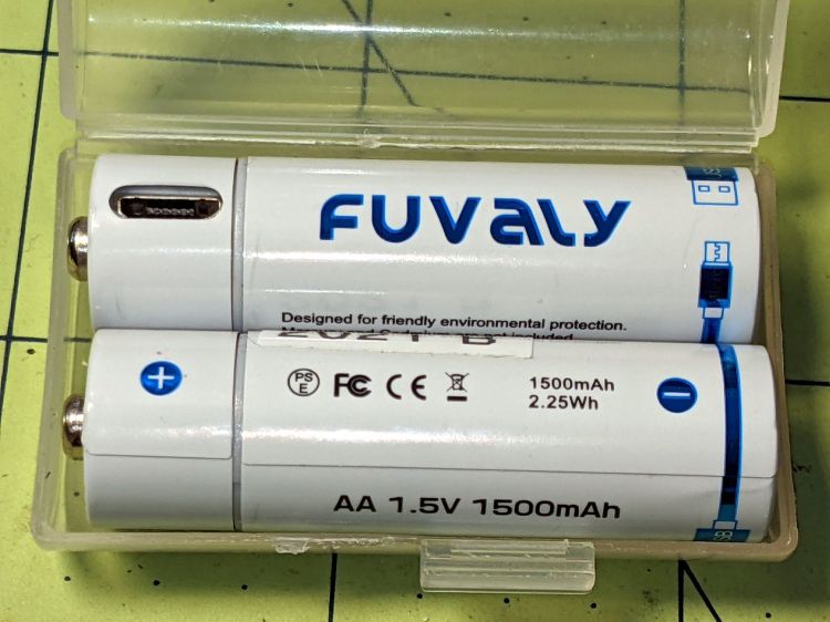
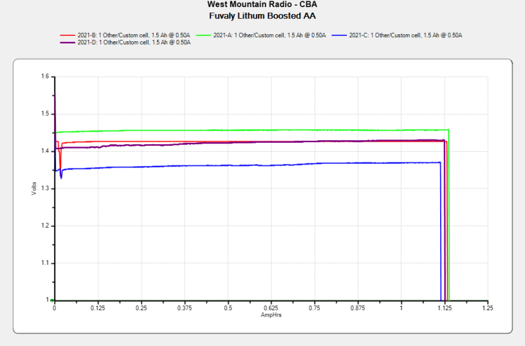
The label claims 1500 mA·h, not the 1120 mA·h I measured:
Fuvaly Bucked Li AA – mAh – 2021-02
My numbers would be higher with a load less than 500 mA. I doubt the 2.5 A maximum current rating.
The claim of 2.25 W·h is rather optimistic:
Fuvaly Bucked Li AA – 2021-02
Back of the envelope: 2.25 W·h at 1.5 V equals 1.5 A·h, all right. If you squint carefully, though, the output voltages run around 1.4 V, some of which is surely IR drop in my battery holder & test wiring, but it still knocks nearly 10% off the wattage and doesn’t seem to add to the runtime.
The camera’s battery charge indicator will obviously show Full right up until it shuts off, but I’ve always carried a spare pair of cells in my pocket anyway.
Recharging them with a USB meter in series required 425 to 600 mA·h at about 4.8 V, so about 2.5 W·h.
Enlarging the instructions from the back of the box, should they become useful:
Fuvaly Bucked Lithium AA – Instructions
Nowhere does the package mention the “brand name”, manufacturer, specifications, or much of anything substantial. I suppose anybody selling white-label products appreciates this level of detail.
The Aluminum Black package directions tell you to apply it with a swab, rinse, and repeat, which seemed like a lot of work for a handful of pins. Instead, I poured a little into a pill bottle, dumped the pins in, and gave it a good shake to coat the pins, whereupon the cap blew off as the contents proceeded to boil merrily. A quick cold-water rinse calmed things down, with no particular harm done, although I had to chase the threads with a tap to get the black powder out. A layer of oil prettied them up nicely.
Today I Learned: the reaction between selenium dioxide and bare aluminum is strongly exothermic.
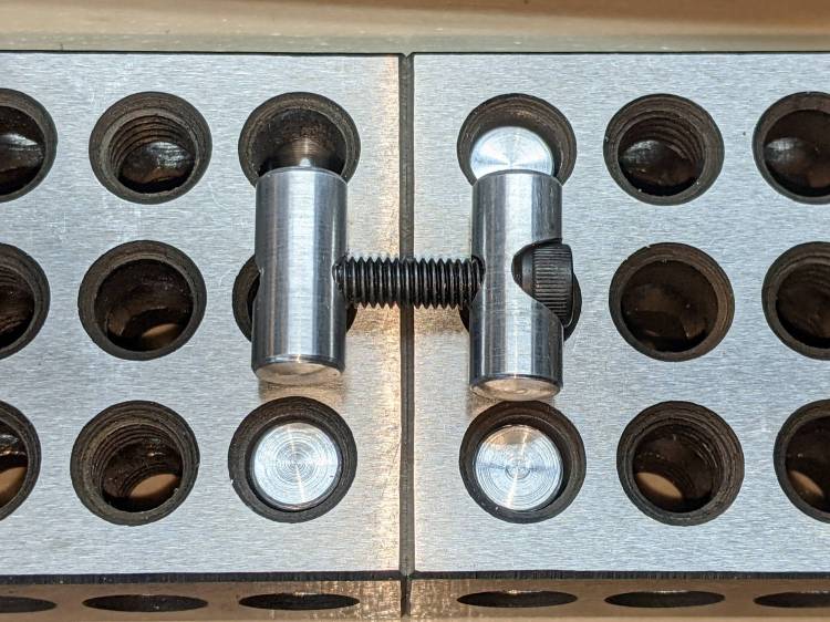
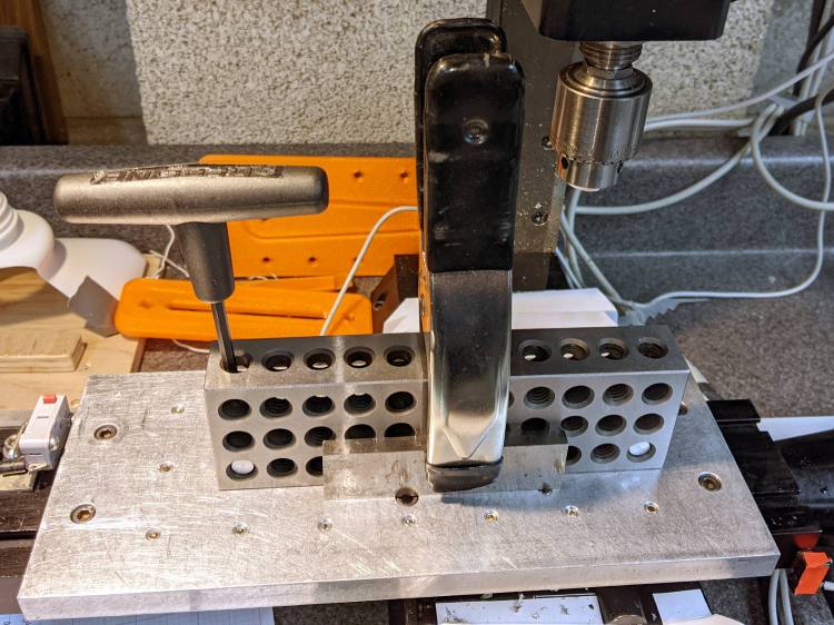
The spring clamp squashes a pair of reasonably straight steel bars against the blocks, whereupon gentle tightening can produce perfect Good Enough™ alignment.
You could remove the tooling plate and attach the blocks directly to the Sherline’s table with two (or more!) T-nuts and screws per block. I expect no standard SHCS length would be quite right for the distance between the head held in the block pin and the T-nut in the table slot, not to mention removing and reinstalling the tooling plate is enough of a nuisance I’d rather not do it without good reason.
Note that the remaining 10-32 clearance hole in the fixture (for the cursor hub) doesn’t align with the underlying hole in the block; the next fixture must take into account both the Sherline and the 123 block grids, as well as which block holes align with the tooling plate. Bleh!
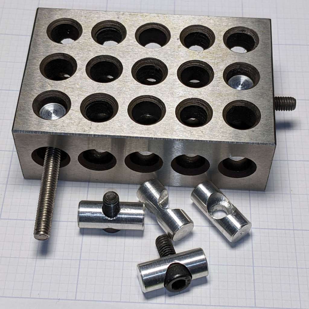
The pins capturing the SHCS heads will mount the 123 blocks to the Sherline’s table or tooling plate, but attaching things to the blocks or joining them requires threaded pins on the other end of the screws:
123 Block Links – trial assembly
Optical illusion: those two pins are the same length.
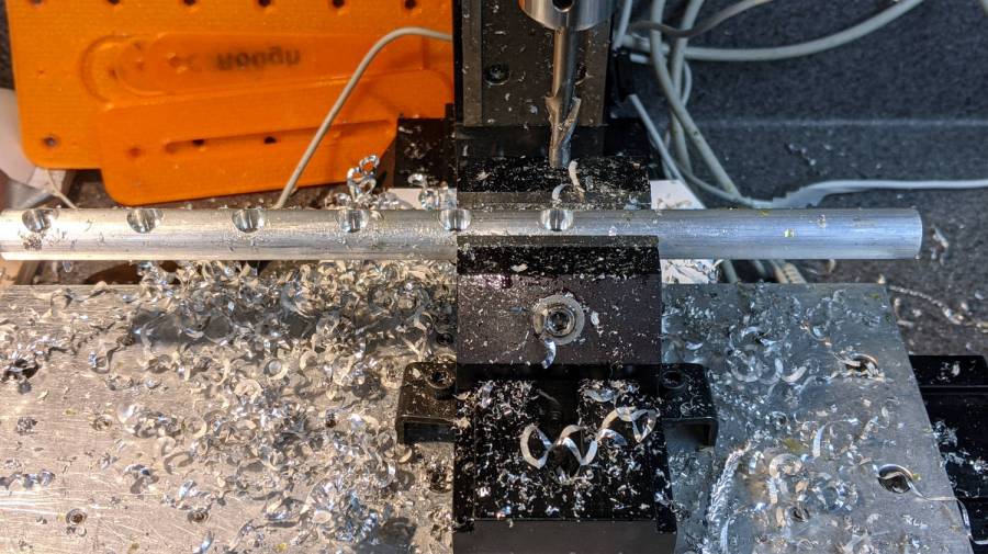
I grabbed a length of 3/8 inch aluminum rod in the Sherline vise, center-drilled four holes spaced 7/8 inch apart, then drilled them with a #20 drill for E-Z tapping.
Space the holes with manual CNC command entry:
GO X[0*0.875*25.4]
GO X[1*0.875*25.4]
GO X[2*0.875*25.4]
GO X[3*0.875*25.4]
That’s LinuxCNC on a Sherline with hard-inch leadscrews and G21 active. I normally use millimeters, but inch dimensions make more sense for these pins.
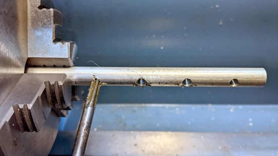
Transfer the rod to the lathe for hand tapping:
123 Block Links – tapping
Not shown here: stick a transfer punch in one of the holes and eyeballometrically align tap with punch to get straight threads.
Then, for each pin:
Chuck rod so the whole pin sticks out
Turn OD to 8.4 mm
Face to 3/8 inch rightward from hole center
Chamfer edge with file
Part off a little more than 3/8 inch leftward from hole center
Find pin in chip tray
Rechuck the other way around
Face to 3/8 inch rightward from hole center
Chamfer edge with file
Ease thread entries with a round file
Done!
Again, I can’t believe I’m the first person to think of these pins; aim me at the commercial offerings I can’t find anywhere.
Update: The keywords “cross dowel nut” and “furniture bolt” will turn up useful products intended for woodworkers. Thanks to blaz for the suggestion.
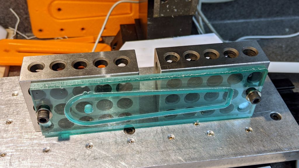
Contemplating a project using a small saw in the Sherline suggested that attaching the workpiece to the side of a 123 block would simplify the machining. My blocks have a centered quintet of 3/8-16 tapped holes through the 2×3 side, all the remaining holes are untapped, and it has no smaller holes. The hole spacing doesn’t match the Sherline tooling plate, but the T-nut slots in the underlying table would suffice.
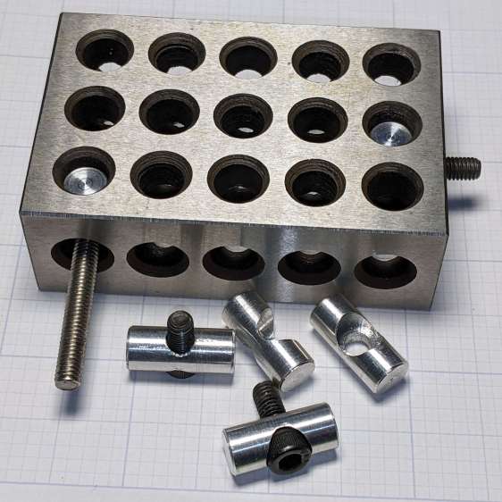
Rather than run long 10-32 screws through the entire block, It Would Be Nice to use short screws from, say, the nearest holes:
123 Block Links – assembled
I cannot possibly be the first person to have this idea, but the obvious keywords don’t produce any useful results on The Intertubes, other than a link to a different (and far more complex) block with counterbored holes of various sizes.
The holes through the blocks probably came from a 5/16 inch drill, the 75% thread depth diameter for the 3/8-16 taps used on the threaded holes. They’re distorted, full of debris, and hardened enough to kill a file, so I eventually settled on 8.2 mm pins that pass through most of the holes.
The socket head screws seat at the pin axis, because the pin diameter is scary close to the counterbore diameter and I didn’t see much point in finesse. I started with a half-inch aluminum rod and peeled it to size, because it simplified the clamping and I have a bunch of them.
The pins are 3/4 inch long to leave a little space on either side of the 1 inch deep holes. I started with comfort marks along the length of the rod:
123 Block Links – laser alignment
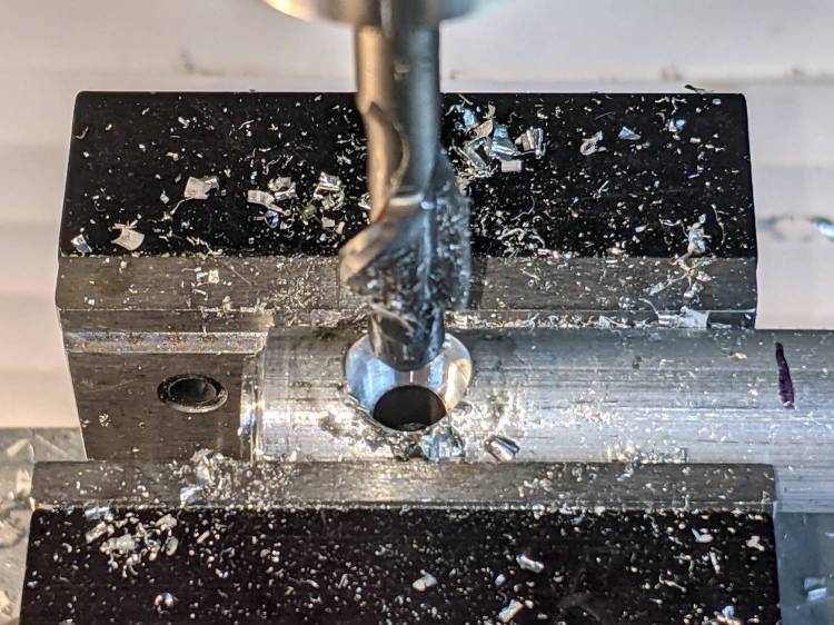
Center-drill so the clearance drill doesn’t skitter off the top:
123 Block Links – center drilling
The counterbore calls for a 0.204 inch = #6 drill, just slightly larger than the #7 clearance drill for a 10-32 screw:
123 Block Links – counterbore
I touched off the counterbore flutes on the sides of the hole, then drilled downward half the 12.8 mm actual rod diameter:
123 Block Links – 10-32 SHCS test fit
Lower the counterbore into the hole again, relax the vise enough to let the rod slide, jog the spindle to X = -25.4 mm, and tighten the vise again:
123 Block Links – index setup
I figured I needed four pins, tops, so make half a dozen to be sure:
123 Block Links – all c-bored
Stick the rod in the mini-lathe chuck, add some comfort marks, and prepare to peel it down to 8.2 mm:
123 Block Links – lathe setup
Having done the lathe work during a Squidwrench remote meeting, I have no pictures of the process, but it goes a little something like this:
Peel off 0.5 mm at a time, stopping just beyond the mark on the left
Mark 3/8 inch on each side of the hole center
Face the end
Chamfer the rim with a file
Clean up the body hole and counterbore
Part the pin off a bit to the left of the mark
Remove the rod
Chuck the pin with the cut off end outward
Face to the mark
Chamfer
Repeat for all six pins
Done!
It’s tedious, but not particularly difficult.
Futher doodling suggested the need for threaded pins to join two blocks together.
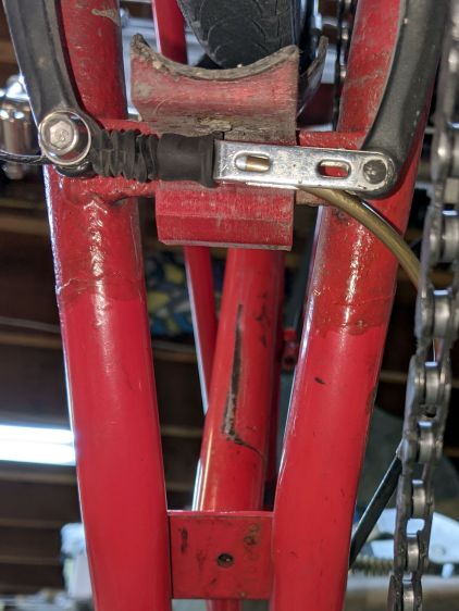
Although our Tour Easy recumbents use ordinary (*) V-brakes, their frame geometry doesn’t route the rear cable quite the way the brake designers expected. Mary’s Medium-Small frame always had its rear brake cable resting against the frame tube, where it bent slightly as she applied the brakes:
Tour Easy rear V-brake layout
That’s looking up from under the rear wheel, with the bike on a workstand, and, yeah, it’s pretty grubby down there.
The squashed rubber boot suggests the brake arms are too close together, but that’s where they must be to hold the brake pads in the proper position, even with new pads and big spacer washers. As a result, the cable stop over on the right at the end of the noodle rests against the frame and dings the paint.
My first thought was to add some length to the end of the noodle inside the stirrup, so I made an adapter with the ID on the noodle end matching the OD on the fitting end:
V-brake – larger noodle – end stop adapter
Which worked poorly, because the noodle has a straight section leading up to the fitting inside the stirrup; any additional length pushes the noodle curve against the stirrup pivot and cants it out of line:
Tour Easy rear V-brake noodle
I’ve been avoiding the fallback plan of building a bigger noodle for years, but finally combined a foot of 3/32 inch brass tubing, a tube bender spring, and various large-diameter round-ish objects from the Basement Warehouse Wing:
V-brake – larger noodle – bending
I annealed the tube by running a torch along its length until the color changed to the obvious “I’m hot enough” copper color, then let it air-cool while I did something else. Brass work-hardens quickly and required two more annealings while finishing that smooth curve; as far as I know, brass doesn’t harden with the heat-and-quench cycle used for steel.
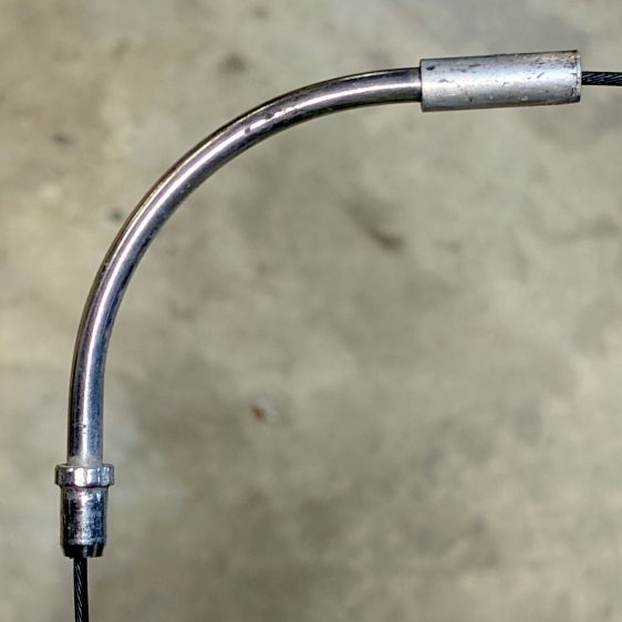
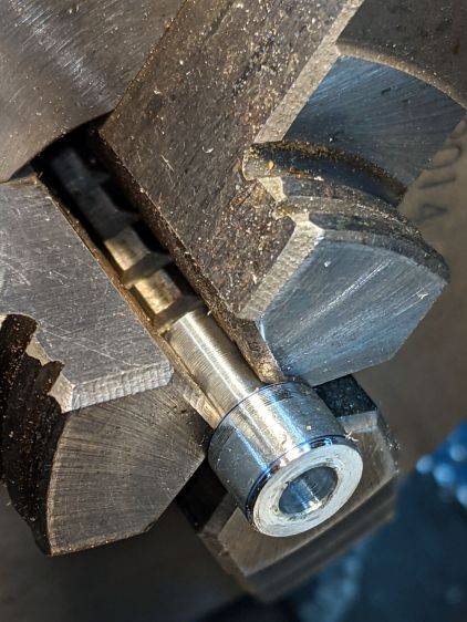
A little more lathe work produced a replacement fitting:
V-brake – larger noodle – end stop
The hole is barely one diameter deep, but I think it’ll align the tube well enough for my simple needs. The failure will most likely involve having the cable chew through the inward side of the mis-aligned tube, which should become obvious in short order.
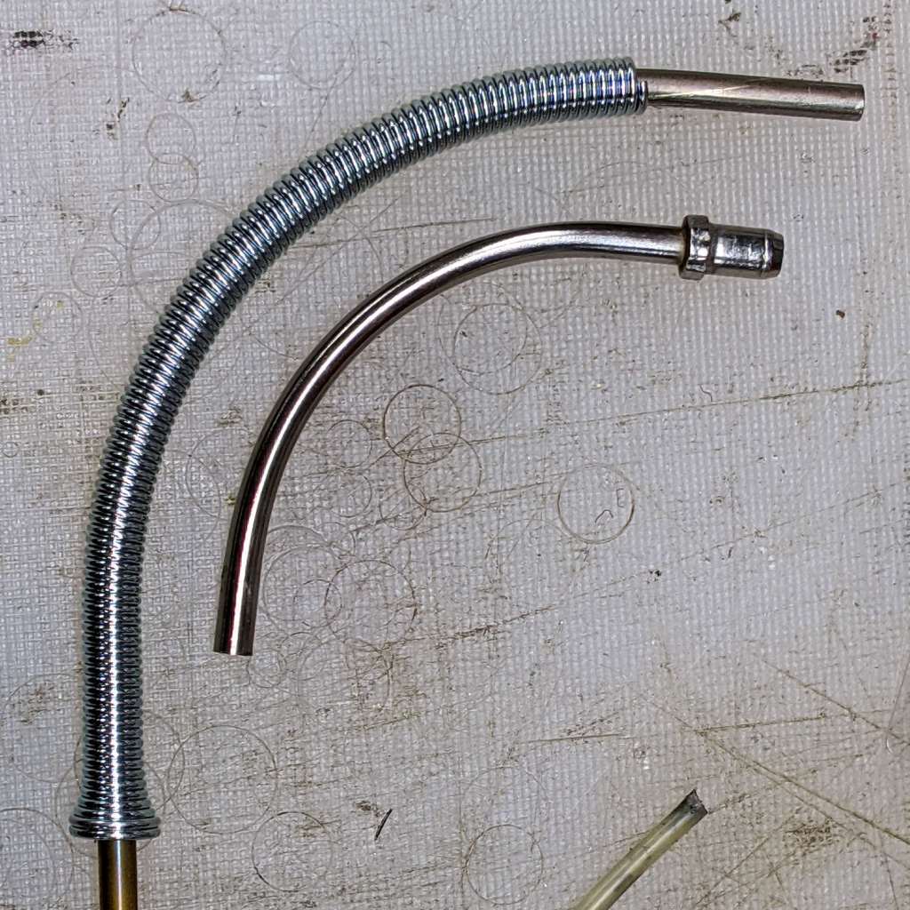
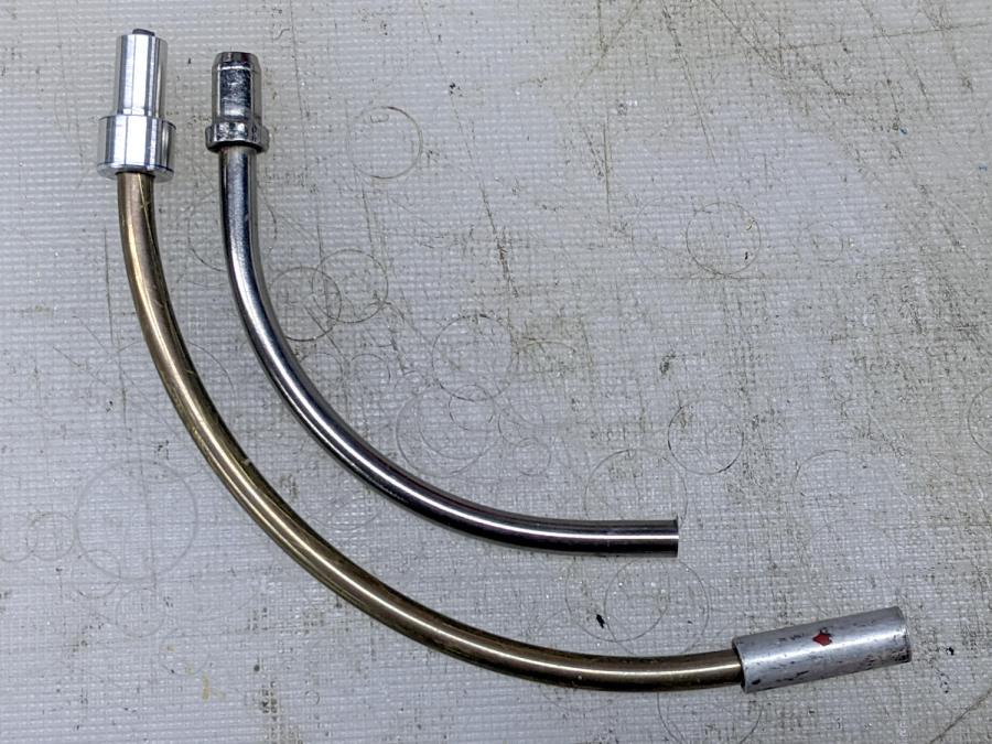
The fitting on the OEM noodle seems to be crimped in place, but I figure my version is unlikely to fall off in normal use:
V-brake – larger noodle vs OEM
Lined up thusly, you can see the reduced straight section behind my fitting and the much larger sweep out to the cable stop.
The OEM noodle had a (presumably) PTFE liner, so I adapted a length of PTFE brake cable liner by mashing the end with various conical objects until it kinda-sorta looked like the cable stop might capture the ragged flange:
V-brake – larger noodle – PTFE liner
Reassembling in reverse order produces a comforting sight:
V-brake – larger noodle – installed
Despite appearances, the new noodle sits below the frame and well above the chain in normal use. In the most extreme small-small cross gearing position the chain barely clears it, but the takeup arm on the rear derailleur starts clattering enough to remind us not to do that.
Brass is certainly not as strong as stainless (?) steel, although I think it ended up in a reasonably hard condition after all the bending. I’m certain neither of us can squeeze the brake lever enough to come anywhere close to causing a problem.
Making a noodle was easier than I expected and, in a month or so, we’ll see how it behaves under actual riding conditions.
(*) “Ordinary” as of many decades ago, because the design dates back to the mid-70s, when Fast Freddy Markham broke 65 mph on a rather customized Easy Racers Gold Rush.
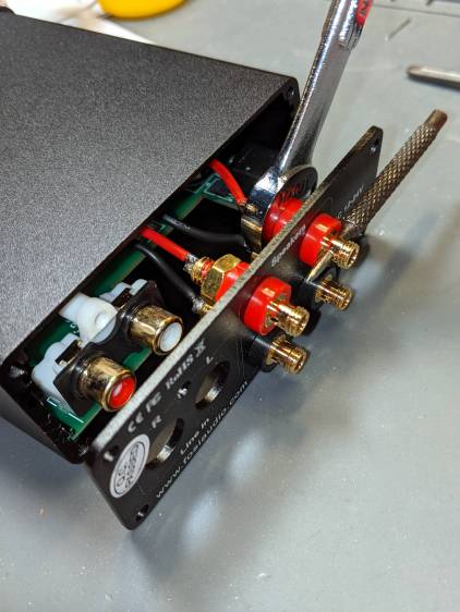
A low-end audio power amp destined for a pair of ancient-yet-still-serviceable speakers arrived, but attempting to poke wires through the side holes of the banana jacks showed they were oriented in random directions. Back in the day, banana jacks had D-shaped shafts fitted into D-shaped panel holes, but those days are gone.
A few minutes with screwdriver, wrench, and (tiny) punch sufficed to line up the holes for E-Z poking:
Fosi audio amp – jack alignment
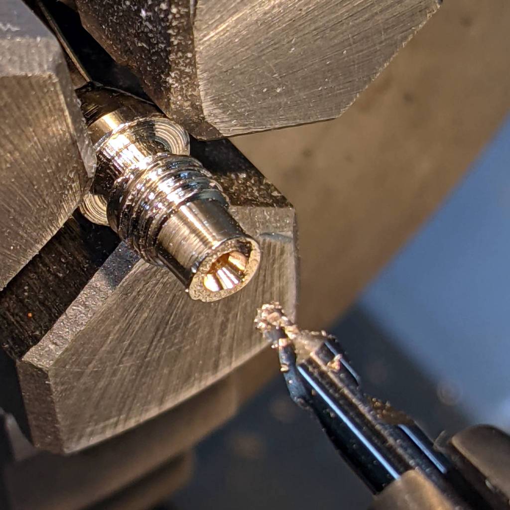
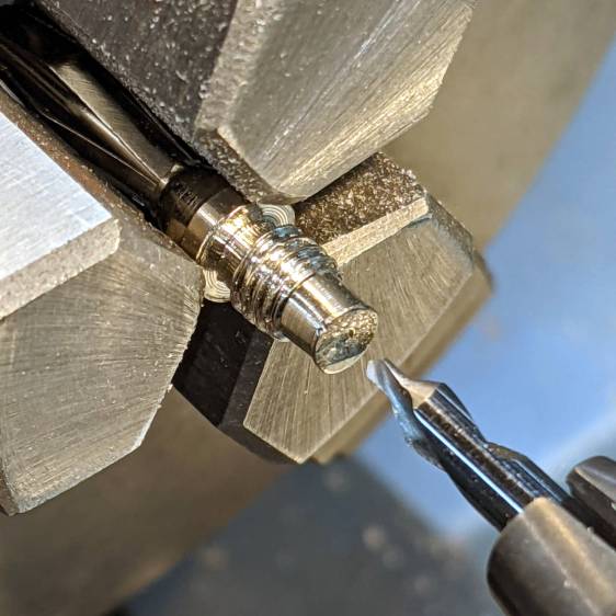
Despite the new convenience, I decided to solder banana plugs to the speaker wires, leading to the discovery my few remaining plugs came from the very bottom of the usability barrel:
Cheap banana plug – solder side
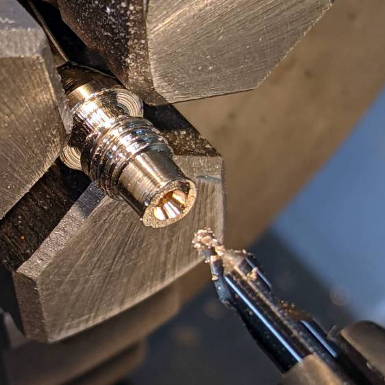
I have no idea how one might affix a wire to that blank stub, but poking a small center drill into the brass lump produces an easily solderable recess:
Cheap banana plug – center drilled
Dab with flux, tin, insert wire, add solder, repeat with all four plugs, and I’m set with a boomin’ system.