|
EESchema-LIBRARY Version 2.4 |
|
#encoding utf-8 |
|
# |
|
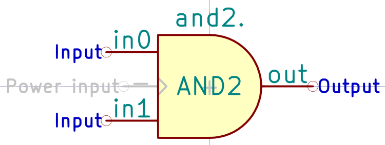
# AND2 |
|
# |
|
DEF AND2 and2. 0 0 N Y 1 F N |
|
F0 "and2." 0 200 50 H V C CNN |
|
F1 "AND2" 0 0 50 H V C CNN |
|
F2 "" 0 0 50 H I C CNN |
|
F3 "" 0 0 50 H I C CNN |
|
F4 "+" 0 0 50 H I C CNN "LoadRT" |
|
DRAW |
|
A 0 0 150 0 900 0 1 0 f 150 0 0 150 |
|
A 0 0 150 0 -900 0 1 0 f 150 0 0 -150 |
|
P 4 0 1 0 0 150 -150 150 -150 -150 0 -150 f |
|
X in0 1 -300 100 150 R 50 50 1 1 I |
|
X in1 2 -300 -100 150 R 50 50 1 1 I |
|
X out 3 300 0 150 L 50 50 1 1 O |
|
X _ 4 -250 0 100 R 50 50 1 1 W NC |
|
ENDDRAW |
|
ENDDEF |
|
# |
|
# COMP |
|
# |
|
DEF COMP comp. 0 20 N Y 1 F N |
|
F0 "comp." -50 300 50 H V C CNN |
|
F1 "COMP" -50 200 50 H V C CNN |
|
F2 "" 300 -50 50 H I C CNN |
|
F3 "" 300 -50 50 H I C CNN |
|
F4 "+" 0 0 50 H I C CNN "LoadRT" |
|
DRAW |
|
T 0 -100 -50 50 0 0 0 + Normal 0 C C |
|
T 0 -100 50 50 0 0 0 – Normal 0 C C |
|
S 200 150 -300 250 0 1 0 f |
|
S -300 150 200 -350 1 1 0 N |
|
X in0 1 -400 50 100 R 50 50 1 1 I |
|
X out 2 300 50 100 L 50 50 1 1 O |
|
X in1 3 -400 -50 100 R 50 50 1 1 I |
|
X hyst 4 -400 -250 154 R 50 50 1 1 I I |
|
X _ 5 -400 -150 100 R 50 50 1 1 W NC |
|
X equal 6 300 -50 100 L 50 50 1 1 O |
|
ENDDRAW |
|
ENDDEF |
|
# |
|
# CONSTANT |
|
# |
|
DEF CONSTANT constant. 0 0 N N 1 F N |
|
F0 "constant." 0 100 50 H I C CNN |
|
F1 "CONSTANT" 200 0 50 H V R CNN |
|
F2 "" 250 -250 50 H I C CNN |
|
F3 "" 250 -250 50 H I C CNN |
|
F4 "+" 0 0 50 H I C CNN "LoadRT" |
|
DRAW |
|
P 4 0 1 0 -400 50 250 50 250 -50 -400 -50 N |
|
X out 1 350 0 100 L 50 50 1 1 O |
|
X _ 2 -500 0 100 R 50 50 1 1 W NC |
|
ENDDRAW |
|
ENDDEF |
|
# |
|
# CONV_FLOAT_S32 |
|
# |
|
DEF CONV_FLOAT_S32 conv-float-s32. 0 20 N Y 1 F N |
|
F0 "conv-float-s32." 0 300 50 H V C CNN |
|
F1 "CONV_FLOAT_S32" 0 200 50 H V C CNN |
|
F2 "" 0 0 50 H I C CNN |
|
F3 "" 0 0 50 H I C CNN |
|
F4 "+" 0 100 50 H I C CNN "LoadRT" |
|
DRAW |
|
S 400 150 -400 250 0 1 0 f |
|
S -400 150 400 -150 1 1 0 N |
|
X in 1 -500 100 100 R 50 50 1 1 I |
|
X clamp 2 -500 -100 157 R 50 50 1 1 I I |
|
X out-of-range 3 500 0 100 L 50 50 1 1 O |
|
X out 4 500 100 100 L 50 50 1 1 O |
|
X _ 5 -500 0 100 R 50 50 1 1 W NC |
|
ENDDRAW |
|
ENDDEF |
|
# |
|
# CONV_FLOAT_U32 |
|
# |
|
DEF CONV_FLOAT_U32 conv-float-u32. 0 40 N Y 1 F N |
|
F0 "conv-float-u32." 0 300 50 H V C CNN |
|
F1 "CONV_FLOAT_U32" 0 200 50 H V C CNN |
|
F2 "" 0 50 50 H I C CNN |
|
F3 "" 0 50 50 H I C CNN |
|
F4 "+" 0 100 50 H I C CNN "LoadRT" |
|
DRAW |
|
S -400 150 400 -150 1 1 0 N |
|
S 400 150 -400 250 1 1 0 f |
|
X in 1 -500 100 100 R 50 50 1 1 I |
|
X clamp 2 -500 -100 157 R 50 50 1 1 I I |
|
X out-of-range 3 500 0 100 L 50 50 1 1 O |
|
X out 4 500 100 100 L 50 50 1 1 O |
|
X _ 5 -500 0 100 R 50 50 1 1 W NC |
|
ENDDRAW |
|
ENDDEF |
|
# |
|
# DBOUNCE |
|
# |
|
DEF DBOUNCE dbounce. 0 20 N Y 1 F N |
|
F0 "dbounce." 0 300 50 H V C CNN |
|
F1 "DBOUNCE" 0 200 50 H V C CNN |
|
F2 "" 600 -350 50 H I C CNN |
|
F3 "" 600 -350 50 H I C CNN |
|
F4 "+" 0 0 50 H I C CNN "LoadRT" |
|
DRAW |
|
S 200 150 -200 250 0 1 0 f |
|
S -200 150 200 -150 1 1 0 N |
|
X in 1 -300 100 100 R 50 50 1 1 I |
|
X out 2 300 100 100 L 50 50 1 1 O |
|
X delay 3 -300 -100 100 R 50 50 1 1 I |
|
X _ 4 -300 0 100 R 50 50 1 1 W NC |
|
ENDDRAW |
|
ENDDEF |
|
# |
|
# FLIPFLOP |
|
# |
|
DEF FLIPFLOP flipflop. 0 20 N Y 1 F N |
|
F0 "flipflop." 0 450 50 H V C CNN |
|
F1 "FLIPFLOP" 0 350 50 H V C CNN |
|
F2 "" 400 -150 50 H I C CNN |
|
F3 "" 400 -150 50 H I C CNN |
|
F4 "+" 0 0 50 H I C CNN "LoadRT" |
|
DRAW |
|
S 200 300 -200 400 0 1 0 f |
|
S -200 300 200 -300 1 1 0 N |
|
X data 2 -300 200 100 R 50 50 1 0 I |
|
X out 5 300 0 100 L 50 50 1 0 O |
|
X reset 1 -300 -200 100 R 50 50 1 1 I |
|
X clk 3 -300 100 100 R 50 50 1 1 I |
|
X set 4 -300 -100 100 R 50 50 1 1 I |
|
X _ 6 -300 0 100 R 50 50 1 1 W NC |
|
ENDDRAW |
|
ENDDEF |
|
# |
|
# HALUI |
|
# |
|
DEF HALUI halui. 0 40 N Y 1 F N |
|
F0 "halui." 0 500 59 H V C CNN |
|
F1 "HALUI" 0 400 50 H V C CNN |
|
F2 "" -150 300 50 H I C CNN |
|
F3 "" -150 300 50 H I C CNN |
|
F4 "1" 350 400 50 H V C CNN "StripAnno" |
|
DRAW |
|
S -400 -300 400 350 0 1 0 N |
|
S -400 450 400 350 0 1 0 f |
|
X abort 1 -500 250 100 R 0 50 1 0 I |
|
X home-all 2 -500 100 100 R 50 50 1 1 I |
|
X mdi-command-00 ~ -500 -100 100 R 50 50 1 1 I |
|
X mdi-command-01 ~ -500 -200 100 R 50 50 1 1 I |
|
ENDDRAW |
|
ENDDEF |
|
# |
|
# HALUI_AXIS |
|
# |
|
DEF HALUI_AXIS halui.axis. 0 40 N Y 1 F N |
|
F0 "halui.axis." 0 400 50 H V C CNN |
|
F1 "HALUI_AXIS" 0 300 50 H V C CNN |
|
F2 "" 450 400 50 H I C CNN |
|
F3 "" 450 400 50 H I C CNN |
|
F4 "1" 500 300 50 H V C CNN "StripAnno" |
|
DRAW |
|
S -550 -50 550 250 0 1 0 N |
|
S 550 350 -550 250 0 1 0 f |
|
X jog-deadband 1 -650 50 100 R 50 50 1 1 I |
|
X jog-speed 2 -650 150 100 R 50 50 1 1 I |
|
X selected 3 650 150 100 L 50 50 1 1 O |
|
ENDDRAW |
|
ENDDEF |
|
# |
|
# HALUI_AXIS_L |
|
# |
|
DEF HALUI_AXIS_L halui.axis.x. 0 40 N Y 1 F N |
|
F0 "halui.axis.x." 0 400 50 H V C CNN |
|
F1 "HALUI_AXIS_L" 0 300 50 H V C CNN |
|
F2 "" -100 350 50 H I C CNN |
|
F3 "" -100 350 50 H I C CNN |
|
F4 "1" 600 300 50 H V C CNN "StripAnno" |
|
DRAW |
|
S -650 350 650 250 0 1 0 f |
|
S 650 250 -650 -600 0 1 0 N |
|
X analog 1 -750 50 100 R 50 50 1 1 I |
|
X pos-relative 10 750 -150 100 L 50 50 1 1 O |
|
X select 11 -750 200 100 R 50 50 1 1 I |
|
X increment 2 -750 -100 100 R 50 50 1 1 I |
|
X increment-minus 3 -750 -200 100 R 50 50 1 1 I |
|
X increment-plus 4 -750 -300 100 R 50 50 1 1 I |
|
X is-selected 5 750 200 100 L 50 50 1 1 O |
|
X minus 6 -750 -450 100 R 50 50 1 1 I |
|
X plus 7 -750 -550 100 R 50 50 1 1 I |
|
X pos-commanded 8 750 50 100 L 50 50 1 1 O |
|
X pos-feedback 9 750 -50 100 L 50 50 1 1 O |
|
ENDDRAW |
|
ENDDEF |
|
# |
|
# HALUI_AXIS_SELECTED |
|
# |
|
DEF HALUI_AXIS_SELECTED halui.axis.selected. 0 40 N Y 1 F N |
|
F0 "halui.axis.selected." 50 400 50 H V C CNN |
|
F1 "HALUI_AXIS_SELECTED" 50 300 50 H V C CNN |
|
F2 "" 1200 850 50 H I C CNN |
|
F3 "" 1200 850 50 H I C CNN |
|
F4 "1" 550 300 50 H V C CNN "StripAnno" |
|
DRAW |
|
S -500 -500 600 250 1 1 0 N |
|
S 600 350 -500 250 1 1 0 f |
|
X increment 1 -600 150 100 R 50 50 1 1 I |
|
X increment-minus 2 -600 0 100 R 50 50 1 1 I |
|
X increment-plus 3 -600 -100 100 R 50 50 1 1 I |
|
X minus 4 -600 -300 100 R 50 50 1 1 I |
|
X plus 5 -600 -400 100 R 50 50 1 1 I |
|
ENDDRAW |
|
ENDDEF |
|
# |
|
# HALUI_ESTOP |
|
# |
|
DEF HALUI_ESTOP halui.estop. 0 40 N Y 1 F N |
|
F0 "halui.estop." 0 300 50 H V C CNN |
|
F1 "HALUI_ESTOP" 0 200 50 H V C CNN |
|
F2 "" 0 0 50 H I C CNN |
|
F3 "" 0 0 50 H I C CNN |
|
F4 "1" 300 200 50 H V C CNN "StripAnno" |
|
DRAW |
|
S -350 -150 350 150 0 1 0 N |
|
S 350 150 -350 250 0 1 0 f |
|
X activate 1 -450 100 100 R 0 50 1 1 I |
|
X is-activated 2 450 0 100 L 0 50 1 1 O |
|
X reset 3 -450 -100 100 R 0 50 1 1 I |
|
ENDDRAW |
|
ENDDEF |
|
# |
|
# HALUI_FEED_OVERRIDE |
|
# |
|
DEF HALUI_FEED_OVERRIDE halui.feed-override. 0 40 N Y 1 F N |
|
F0 "halui.feed-override." 0 450 50 H V C CNN |
|
F1 "HALUI_FEED_OVERRIDE" 0 350 50 H V C CNN |
|
F2 "" 200 50 50 H I C CNN |
|
F3 "" 200 50 50 H I C CNN |
|
F4 "1" 500 350 50 H V C CNN "StripAnno" |
|
DRAW |
|
S -450 -400 450 300 0 1 0 N |
|
S 450 300 -450 400 0 1 0 f |
|
X count-enable 1 -550 250 100 R 0 50 1 1 I |
|
X counts 2 -550 150 100 R 0 50 1 1 I |
|
X decrease 3 -550 -100 100 R 0 50 1 1 I |
|
X direct-value 4 -550 -250 100 R 0 50 1 1 I |
|
X increase 5 -550 0 100 R 0 50 1 1 I |
|
X scale 6 -550 -350 100 R 0 50 1 1 I |
|
X value 7 550 250 100 L 0 50 1 1 O |
|
ENDDRAW |
|
ENDDEF |
|
# |
|
# HALUI_FLOOD |
|
# |
|
DEF HALUI_FLOOD halui.flood. 0 40 N Y 1 F N |
|
F0 "halui.flood." 0 250 50 H V C CNN |
|
F1 "HALUI_FLOOD" 0 150 50 H V C CNN |
|
F2 "" 0 0 50 H I C CNN |
|
F3 "" 0 0 50 H I C CNN |
|
F4 "1" 350 150 50 H V C CNN "StripAnno" |
|
DRAW |
|
S -300 100 300 -100 1 1 0 N |
|
S -300 200 300 100 1 1 0 f |
|
X is-on 1 400 0 100 L 0 50 1 1 O |
|
X off 2 -400 -50 100 R 0 50 1 1 I |
|
X on 3 -400 50 100 R 0 50 1 1 I |
|
ENDDRAW |
|
ENDDEF |
|
# |
|
# HALUI_JOINT |
|
# |
|
DEF HALUI_JOINT halui.joint. 0 40 N Y 1 F N |
|
F0 "halui.joint." 0 200 50 H V C CNN |
|
F1 "HALUI_JOINT" 0 100 50 H V C CNN |
|
F2 "" 750 150 50 H I C CNN |
|
F3 "" 750 150 50 H I C CNN |
|
F4 "1" 400 100 50 H V C CNN "StripAnno" |
|
DRAW |
|
S 450 50 -450 -250 1 1 0 N |
|
S 450 50 -450 150 1 1 0 f |
|
X jog-deadband 1 -550 -150 100 R 50 50 1 1 I |
|
X selected 2 550 -50 100 L 50 50 1 1 O |
|
X jog-speed 3 -550 -50 100 R 50 50 1 1 I |
|
ENDDRAW |
|
ENDDEF |
|
# |
|
# HALUI_JOINT_N |
|
# |
|
DEF HALUI_JOINT_N halui.joint.0. 0 40 N Y 1 F N |
|
F0 "halui.joint.0." 0 300 50 H V C CNN |
|
F1 "HALUI_JOINT_N" 0 200 50 H V C CNN |
|
F2 "" 400 300 50 H I C CNN |
|
F3 "" 400 300 50 H I C CNN |
|
F4 "1" 700 200 50 H V C CNN "StripAnno" |
|
DRAW |
|
S -800 -1050 750 150 0 1 0 N |
|
S 750 150 -800 250 0 1 0 f |
|
X minus 1 -900 -850 100 R 50 50 1 1 I |
|
X analog 10 -900 -350 100 R 50 50 1 1 I |
|
X is-selected 11 850 50 100 L 50 50 1 1 O |
|
X is-homed 12 850 -100 100 L 50 50 1 1 O |
|
X increment-plus 13 -900 -700 100 R 50 50 1 1 I |
|
X increment-minus 14 -900 -600 100 R 50 50 1 1 I |
|
X increment 15 -900 -500 100 R 50 50 1 1 I |
|
X home 16 -900 -100 100 R 50 50 1 1 I |
|
X has-fault 17 850 -950 100 L 50 50 1 1 O |
|
X unhome 2 -900 -200 100 R 50 50 1 1 I |
|
X select 3 -900 50 100 R 50 50 1 1 I |
|
X plus 4 -900 -950 100 R 50 50 1 1 I |
|
X override-limits 5 850 -850 100 L 50 50 1 1 O |
|
X on-soft-min-limit 6 850 -700 100 L 50 50 1 1 O |
|
X on-soft-max-limit 7 850 -600 100 L 50 50 1 1 O |
|
X on-hard-min-limit 8 850 -450 100 L 50 50 1 1 O |
|
X on-hard-max-limit 9 850 -350 100 L 50 50 1 1 O |
|
ENDDRAW |
|
ENDDEF |
|
# |
|
# HALUI_JOINT_SELECTED |
|
# |
|
DEF HALUI_JOINT_SELECTED halui.joint.selected. 0 40 N Y 1 F N |
|
F0 "halui.joint.selected." 0 500 50 H V C CNN |
|
F1 "HALUI_JOINT_SELECTED" 0 400 50 H V C CNN |
|
F2 "" 150 450 50 H I C CNN |
|
F3 "" 150 450 50 H I C CNN |
|
F4 "1" 700 400 50 H V C CNN "StripAnno" |
|
DRAW |
|
S 750 350 -800 -550 0 1 0 N |
|
S 750 350 -800 450 0 1 0 f |
|
X is-homed 1 850 250 100 L 50 50 1 1 O |
|
X increment-plus 10 -900 -200 100 R 50 50 1 1 I |
|
X increment-minus 11 -900 -100 100 R 50 50 1 1 I |
|
X increment 12 -900 0 100 R 50 50 1 1 I |
|
X home 13 -900 250 100 R 50 50 1 1 I |
|
X has-fault 14 850 150 100 L 50 50 1 1 O |
|
X unhome 2 -900 150 100 R 50 50 1 1 I |
|
X plus 3 -900 -450 100 R 50 50 1 1 I |
|
X override-limits 4 850 -450 100 L 50 50 1 1 O |
|
X on-soft-min-limit 5 850 -350 100 L 50 50 1 1 O |
|
X on-soft-max-limit 6 850 -250 100 L 50 50 1 1 O |
|
X on-hard-min-limit 7 850 -100 100 L 50 50 1 1 O |
|
X on-hard-max-limit 8 850 0 100 L 50 50 1 1 O |
|
X minus 9 -900 -350 100 R 50 50 1 1 I |
|
ENDDRAW |
|
ENDDEF |
|
# |
|
# HALUI_LUBE |
|
# |
|
DEF HALUI_LUBE halui.lube. 0 40 N Y 1 F N |
|
F0 "halui.lube." 0 250 50 H V C CNN |
|
F1 "HALUI_LUBE" -50 150 50 H V C CNN |
|
F2 "" 0 0 50 H I C CNN |
|
F3 "" 0 0 50 H I C CNN |
|
F4 "1" 250 150 50 H V C CNN "StripAnno" |
|
DRAW |
|
S -300 100 300 -100 1 1 0 N |
|
S -300 200 300 100 1 1 0 f |
|
X is-on 1 400 0 100 L 0 50 1 1 O |
|
X off 2 -400 -50 100 R 0 50 1 1 I |
|
X on 3 -400 50 100 R 0 50 1 1 I |
|
ENDDRAW |
|
ENDDEF |
|
# |
|
# HALUI_MACHINE |
|
# |
|
DEF HALUI_MACHINE halui.machine. 0 40 N Y 1 F N |
|
F0 "halui.machine." 0 300 50 H V C CNN |
|
F1 "HALUI_MACHINE" 0 200 50 H V C CNN |
|
F2 "" 2450 1450 50 H I C CNN |
|
F3 "" 2450 1450 50 H I C CNN |
|
F4 "1" 400 200 50 H V C CNN "StripAnno" |
|
DRAW |
|
S -400 -250 450 150 0 1 0 N |
|
S 450 150 -400 250 0 1 0 f |
|
X is-on 1 550 50 100 L 0 50 1 1 O |
|
X off 2 -500 -50 100 R 0 50 1 1 I |
|
X on 3 -500 50 100 R 0 50 1 1 I |
|
X units-per-mm 4 550 -150 100 L 50 50 1 1 O |
|
ENDDRAW |
|
ENDDEF |
|
# |
|
# HALUI_MAX_VELOCITY |
|
# |
|
DEF HALUI_MAX_VELOCITY halui.max-velocity. 0 40 N Y 1 F N |
|
F0 "halui.max-velocity." 0 550 50 H V C CNN |
|
F1 "HALUI_MAX_VELOCITY" -50 450 50 H V C CNN |
|
F2 "" 1350 900 50 H I C CNN |
|
F3 "" 1350 900 50 H I C CNN |
|
F4 "1" 450 450 50 H V C CNN "StripAnno" |
|
DRAW |
|
S -500 -400 500 400 0 1 0 N |
|
S 500 400 -500 500 0 1 0 f |
|
X direct-value 1 -600 -200 100 R 50 50 0 0 I |
|
X count 2 -600 200 100 R 0 50 1 1 I |
|
X count-enable 3 -600 300 100 R 0 50 1 1 I |
|
X decrease 4 -600 50 100 R 0 50 1 1 I |
|
X increase 5 -600 -50 100 R 0 50 1 1 I |
|
X scale 6 -600 -300 100 R 0 50 1 1 I |
|
X value 7 600 200 100 L 0 50 1 1 O |
|
ENDDRAW |
|
ENDDEF |
|
# |
|
# HALUI_MIST |
|
# |
|
DEF HALUI_MIST halui.mist. 0 40 N Y 1 F N |
|
F0 "halui.mist." 0 250 50 H V C CNN |
|
F1 "HALUI_MIST" 0 150 50 H V C CNN |
|
F2 "" 0 -50 50 H I C CNN |
|
F3 "" 0 -50 50 H I C CNN |
|
F4 "1" 300 150 50 H V C CNN "StripAnno" |
|
DRAW |
|
S -300 100 350 -100 0 1 0 N |
|
S -300 200 350 100 0 1 0 f |
|
X is-on 1 450 0 100 L 0 50 1 1 O |
|
X off 2 -400 -50 100 R 0 50 1 1 I |
|
X on 3 -400 50 100 R 0 50 1 1 I |
|
ENDDRAW |
|
ENDDEF |
|
# |
|
# HALUI_MODE |
|
# |
|
DEF HALUI_MODE halui.mode. 0 40 N Y 1 F N |
|
F0 "halui.mode." 0 500 50 H V C CNN |
|
F1 "HALUI_MODE" 0 400 50 H V C CNN |
|
F2 "" 900 750 50 H I C CNN |
|
F3 "" 900 750 50 H I C CNN |
|
F4 "1" 350 400 50 H V C CNN "StripAnno" |
|
DRAW |
|
S -400 -650 400 350 0 1 0 N |
|
S 400 350 -400 450 0 1 0 f |
|
X auto 1 -500 250 100 R 0 50 1 1 I |
|
X teleop 10 -500 -550 100 R 0 50 1 1 I |
|
X is-auto 2 500 250 100 L 0 50 1 1 O |
|
X is-joint 3 500 50 100 L 0 50 1 1 O |
|
X is-manual 4 500 -150 100 L 0 50 1 1 O |
|
X is-mdi 5 500 -350 100 L 0 50 1 1 O |
|
X is-teleop 6 500 -550 100 L 0 50 1 1 O |
|
X joint 7 -500 50 100 R 0 50 1 1 I |
|
X manual 8 -500 -150 100 R 0 50 1 1 I |
|
X mdi 9 -500 -350 100 R 0 50 1 1 I |
|
ENDDRAW |
|
ENDDEF |
|
# |
|
# HALUI_PROGRAM |
|
# |
|
DEF HALUI_PROGRAM halui.program. 0 40 N Y 1 F N |
|
F0 "halui.program." -50 550 50 H V C CNN |
|
F1 "HALUI_PROGRAM" -50 450 50 H V C CNN |
|
F2 "" 50 300 50 H I C CNN |
|
F3 "" 50 300 50 H I C CNN |
|
F4 "1" 400 450 50 H V C CNN "StripAnno" |
|
DRAW |
|
S -500 400 450 -950 0 1 0 N |
|
S 450 400 -500 500 0 1 0 f |
|
X block-delete.is-on 1 550 -750 100 L 0 50 1 1 O |
|
X pause 10 -600 -50 100 R 0 50 1 1 I |
|
X resume 11 -600 -150 100 R 0 50 1 1 I |
|
X run 12 -600 300 100 R 0 50 1 1 I |
|
X step 13 -600 200 100 R 0 50 1 1 I |
|
X stop 14 -600 100 100 R 0 50 1 1 I |
|
X block-delete.off 2 -600 -850 100 R 0 50 1 1 I |
|
X block-delete.on 3 -600 -650 100 R 0 50 1 1 I |
|
X is-idle 4 550 200 100 L 0 50 1 1 O |
|
X is-paused 5 550 -50 100 L 0 50 1 1 O |
|
X is-running 6 550 300 100 L 0 50 1 1 O |
|
X optional-stop.is-on 7 550 -400 100 L 0 50 1 1 O |
|
X optional-stop.off 8 -600 -500 100 R 0 50 1 1 I |
|
X optional-stop.on 9 -600 -300 100 R 0 50 1 1 I |
|
ENDDRAW |
|
ENDDEF |
|
# |
|
# HALUI_RAPID_OVERRIDE |
|
# |
|
DEF HALUI_RAPID_OVERRIDE halui.rapid-override. 0 40 N Y 1 F N |
|
F0 "halui.rapid-override." 0 450 50 H V C CNN |
|
F1 "HALUI_RAPID_OVERRIDE" -50 350 50 H V C CNN |
|
F2 "" 1050 750 50 H I C CNN |
|
F3 "" 1050 750 50 H I C CNN |
|
F4 "1" 500 350 50 H V C CNN "StripAnno" |
|
DRAW |
|
S -550 -500 550 300 1 1 0 N |
|
S 550 300 -550 400 1 1 0 f |
|
X count-enable 1 -650 200 100 R 0 50 1 1 I |
|
X counts 2 -650 100 100 R 0 50 1 1 I |
|
X decrease 3 -650 -150 100 R 0 50 1 1 I |
|
X direct-value 4 -650 -300 100 R 0 50 1 1 I |
|
X increase 5 -650 -50 100 R 0 50 1 1 I |
|
X scale 6 -650 -400 100 R 0 50 1 1 I |
|
X value 7 650 200 100 L 0 50 1 1 O |
|
ENDDRAW |
|
ENDDEF |
|
# |
|
# HALUI_SPINDLE_N |
|
# |
|
DEF HALUI_SPINDLE_N halui.spindle.0. 0 40 N Y 1 F N |
|
F0 "halui.spindle.0." 0 900 50 H V C CNN |
|
F1 "HALUI_SPINDLE_N" 0 800 50 H V C CNN |
|
F2 "" -50 1450 50 H I C CNN |
|
F3 "" -50 1450 50 H I C CNN |
|
F4 "1" 550 800 50 H V C CNN "StripAnno" |
|
DRAW |
|
S -650 -950 600 750 0 1 0 N |
|
S 600 750 -650 850 0 1 0 f |
|
X override.direct-value 11 -750 -850 100 R 50 50 0 0 I |
|
X override.counts 1 -750 -550 100 R 0 50 1 1 I |
|
X override.decrease 10 -750 -650 100 R 0 50 1 1 I |
|
X override.count-enable 12 -750 -450 100 R 0 50 1 1 I |
|
X is-on 13 700 -100 100 L 0 50 1 1 O |
|
X increase 14 -750 150 100 R 0 50 1 1 I |
|
X forward 15 -750 400 100 R 0 50 1 1 I |
|
X decrease 16 -750 50 100 R 0 50 1 1 I |
|
X brake.off 17 -750 550 100 R 0 50 1 1 I |
|
X brake-on 18 -750 650 100 R 0 50 1 1 I |
|
X brake-is-on 19 700 650 100 L 0 50 1 1 O |
|
X stop 2 -750 -200 100 R 0 50 1 1 I |
|
X start 3 -750 -100 100 R 0 50 1 1 I |
|
X runs-forward 4 700 400 100 L 0 50 1 1 O |
|
X runs-backwards 5 700 300 100 L 0 50 1 1 O |
|
X reverse 6 -750 300 100 R 0 50 1 1 I |
|
X override.value 7 700 -350 100 L 0 50 1 1 O |
|
X override.scale 8 -750 -350 100 R 0 50 1 1 I |
|
X override.increase 9 -750 -750 100 R 0 50 1 1 I |
|
ENDDRAW |
|
ENDDEF |
|
# |
|
# HALUI_TOOL |
|
# |
|
DEF HALUI_TOOL halui.tool. 0 40 N Y 1 F N |
|
F0 "halui.tool." -50 750 50 H V C CNN |
|
F1 "HALUI_TOOL" -50 650 50 H V C CNN |
|
F2 "" -50 300 50 H I C CNN |
|
F3 "" -50 300 50 H I C CNN |
|
F4 "1" 250 650 50 H V C CNN "StripAnno" |
|
DRAW |
|
S -400 600 300 700 0 1 0 f |
|
S 300 600 -400 -800 0 1 0 N |
|
X diameter 1 400 400 100 L 0 50 1 1 O |
|
X length-offset.z 10 400 -700 100 L 0 50 1 1 O |
|
X number 11 400 500 100 L 0 50 1 1 O |
|
X length-offset.a 2 400 250 100 L 0 50 1 1 O |
|
X length-offset.b 3 400 150 100 L 0 50 1 1 O |
|
X length-offset.c 4 400 50 100 L 0 50 1 1 O |
|
X length-offset.u 5 400 -150 100 L 0 50 1 1 O |
|
X length-offset.v 6 400 -250 100 L 0 50 1 1 O |
|
X length-offset.w 7 400 -350 100 L 0 50 1 1 O |
|
X length-offset.x 8 400 -500 100 L 0 50 1 1 O |
|
X length-offset.y 9 400 -600 100 L 0 50 1 1 O |
|
ENDDRAW |
|
ENDDEF |
|
# |
|
# HAL_MANUALTOOLCHANGE |
|
# |
|
DEF HAL_MANUALTOOLCHANGE hal_manualtoolchange. 0 40 Y Y 1 F N |
|
F0 "hal_manualtoolchange." -50 300 59 H V C CNN |
|
F1 "HAL_MANUALTOOLCHANGE" -100 200 50 H V C CNN |
|
F2 "" 0 -100 50 H I C CNN |
|
F3 "" 0 -100 50 H I C CNN |
|
F4 "1" 450 200 50 H V C CNN "StripAnno" |
|
F5 "-W hal_manualtoolchange" -50 100 50 H V C CNN "LoadUsr" |
|
DRAW |
|
S -600 -450 500 50 1 1 0 N |
|
S 500 50 -600 250 1 1 0 f |
|
X change 1 -700 -50 100 R 0 50 1 0 I |
|
X change_button 2 -700 -200 100 R 0 50 1 0 I |
|
X changed 3 600 -50 100 L 0 50 1 0 O |
|
X number 4 -700 -350 100 R 0 50 1 0 I |
|
ENDDRAW |
|
ENDDEF |
|
# |
|
# HM2_BOARD |
|
# |
|
DEF HM2_BOARD [HM2](C0). 0 20 N Y 1 F N |
|
F0 "[HM2](C0)." 0 500 50 H V C CNN |
|
F1 "HM2_BOARD" 0 400 50 H V C CNN |
|
F2 "" 550 -200 50 H I C CNN |
|
F3 "" 550 -200 50 H I C CNN |
|
F4 "1" 400 400 50 H V C CNN "StripAnno" |
|
DRAW |
|
S -450 350 450 -550 0 1 0 N |
|
S 450 350 -450 450 0 1 0 f |
|
X watchdog.timeout_ns 8 -550 50 157 R 50 50 1 0 I I |
|
X watchdog.has_bit 1 550 -50 100 L 50 50 1 1 O |
|
X led.CR01 2 -550 300 100 R 50 50 1 1 I |
|
X led.CR02 3 -550 200 100 R 50 50 1 1 I |
|
X read 4 -550 -150 100 R 50 50 1 1 W C |
|
X *read_gpio 5 -550 -350 100 R 50 50 1 1 W NC |
|
X write 6 -550 -250 100 R 50 50 1 1 W C |
|
X *write_gpio 7 -550 -450 100 R 50 50 1 1 W NC |
|
ENDDRAW |
|
ENDDEF |
|
# |
|
# HM2_GPIO |
|
# |
|
DEF HM2_GPIO [HM2](C0).gpio.000. 0 40 N Y 1 F N |
|
F0 "[HM2](C0).gpio.000." 0 300 50 H V C CNN |
|
F1 "HM2_GPIO" -50 200 50 H V C CNN |
|
F2 "" 150 -250 50 H I C CNN |
|
F3 "" 150 -250 50 H I C CNN |
|
F4 "1" 350 200 50 H V C CNN "StripAnno" |
|
DRAW |
|
S -400 150 400 250 0 1 0 f |
|
S 400 150 -400 -350 0 1 0 N |
|
X in 1 500 100 100 L 50 50 1 1 O |
|
X in_not 2 500 0 100 L 50 50 1 1 O |
|
X invert_output 3 -500 -200 157 R 50 50 1 1 I I |
|
X is_opendrain 4 -500 -300 157 R 50 50 1 1 I I |
|
X is_output 5 -500 -100 157 R 50 50 1 1 I I |
|
X out 6 -500 100 100 R 50 50 1 1 I |
|
ENDDRAW |
|
ENDDEF |
|
# |
|
# HM2_PWMGEN |
|
# |
|
DEF HM2_PWMGEN [HM2](C0).pwmgen. 0 40 N Y 1 F N |
|
F0 "[HM2](C0).pwmgen." 0 550 50 H V C CNN |
|
F1 "HM2_PWMGEN" 0 450 50 H V C CNN |
|
F2 "" 0 0 50 H I C CNN |
|
F3 "" 0 0 50 H I C CNN |
|
F4 "1" 450 450 50 H V C CNN "StripAnno" |
|
DRAW |
|
S -450 400 500 100 1 1 0 N |
|
S -450 500 500 400 1 1 0 f |
|
X pdm_frequency 1 -550 200 157 R 50 50 1 1 I I |
|
X pwm_frequency 2 -550 300 157 R 50 50 1 1 I I |
|
ENDDRAW |
|
ENDDEF |
|
# |
|
# HM2_PWMGEN_N |
|
# |
|
DEF HM2_PWMGEN_N [HM2](C0).pwmgen.00. 0 40 N Y 1 F N |
|
F0 "[HM2](C0).pwmgen.00." 0 650 50 H V C CNN |
|
F1 "HM2_PWMGEN_N" 0 550 50 H V C CNN |
|
F2 "" 0 -250 50 H I C CNN |
|
F3 "" 0 -250 50 H I C CNN |
|
F4 "1" 450 550 50 H V C CNN "StripAnno" |
|
DRAW |
|
S -450 500 500 -700 1 1 0 N |
|
S -450 600 500 500 1 1 0 f |
|
X value 1 -550 400 100 R 50 50 1 1 I |
|
X enable 2 -550 300 100 R 50 50 1 1 I |
|
X scale 3 -550 150 157 R 50 50 1 1 I I |
|
X output-type 4 -550 0 157 R 50 50 1 1 I I |
|
X out0.invert_output 5 -550 -250 157 R 50 50 1 1 I I |
|
X out1.invert_output 6 -550 -500 157 R 50 50 1 1 I I |
|
X offset-mode 7 -550 -100 157 R 50 50 1 1 I I |
|
X out0.is_opendrain 8 -550 -350 157 R 50 50 1 1 I I |
|
X out1.is_opendrain 9 -550 -600 157 R 50 50 1 1 I I |
|
ENDDRAW |
|
ENDDEF |
|
# |
|
# HM2_STEPGEN |
|
# |
|
DEF HM2_STEPGEN [HM2](C0).stepgen.00. 0 20 N Y 1 F N |
|
F0 "[HM2](C0).stepgen.00." -50 900 50 H V C CNN |
|
F1 "HM2_STEPGEN" -50 800 50 H V C CNN |
|
F2 "" 0 500 50 H I C CNN |
|
F3 "" 0 500 50 H I C CNN |
|
F4 "1" 400 800 50 H V C CNN "StripAnno" |
|
DRAW |
|
S -500 750 450 -1250 0 1 0 N |
|
S -500 850 450 750 0 1 0 f |
|
X control-type 1 -600 500 100 R 50 50 1 1 I |
|
X position-scale 10 -600 -50 157 R 50 50 1 1 I I |
|
X step_type 11 -600 -1150 157 R 50 50 1 1 I I |
|
X steplen 12 -600 -200 157 R 50 50 1 1 I I |
|
X stepspace 13 -600 -300 157 R 50 50 1 1 I I |
|
X step.invert_output 14 -600 -400 157 R 50 50 1 1 I I |
|
X direction.invert_output 15 -600 -750 157 R 50 50 1 1 I I |
|
X velocity-cmd 16 -600 200 100 R 50 50 1 1 I |
|
X velocity-fb 17 550 100 100 L 50 50 1 1 O |
|
X counts 2 550 650 100 L 50 50 1 1 O |
|
X dirhold 3 -600 -650 157 R 50 50 1 1 I I |
|
X dirsetup 4 -600 -550 157 R 50 50 1 1 I I |
|
X enable 5 -600 650 100 R 50 50 1 1 I |
|
X maxaccel 6 -600 -1000 157 R 50 50 1 1 I I |
|
X maxvel 7 -600 -900 157 R 50 50 1 1 I I |
|
X position-cmd 8 -600 400 100 R 50 50 1 1 I |
|
X position-fb 9 550 300 100 L 50 50 1 1 O |
|
ENDDRAW |
|
ENDDEF |
|
# |
|
# IOCONTROL |
|
# |
|
DEF IOCONTROL iocontrol.0. 0 40 N Y 1 F N |
|
F0 "iocontrol.0." 0 700 59 H V C CNN |
|
F1 "IOCONTROL" 0 600 50 H V C CNN |
|
F2 "" -100 200 50 H I C CNN |
|
F3 "" -100 200 50 H I C CNN |
|
F4 "1" 650 600 50 H V C CNN "StripAnno" |
|
DRAW |
|
S -750 550 700 650 1 1 0 f |
|
S 700 550 -750 -950 1 1 0 N |
|
X coolant-flood 1 800 -50 100 L 0 50 1 0 O |
|
X tool-prep-pocket 10 800 -750 100 L 0 50 1 0 O |
|
X tool-prepare 11 800 -550 100 L 0 50 1 0 O |
|
X tool-prepared 12 -850 -550 100 R 0 50 1 0 I |
|
X user-enable-out 13 800 450 100 L 0 50 1 0 O |
|
X user-request-enable 14 800 350 100 L 0 50 1 0 O |
|
X coolant-mist 2 800 -150 100 L 0 50 1 0 O |
|
X emc-enable-in 3 -850 450 100 R 0 50 1 0 I |
|
X lube 4 800 150 100 L 0 50 1 0 O |
|
X lube-level 5 -850 150 100 R 0 50 1 0 I |
|
X tool-change 6 800 -850 100 L 0 50 1 0 O |
|
X tool-changed 7 -850 -850 100 R 0 50 1 0 I |
|
X tool-number 8 800 -350 100 L 0 50 1 0 O |
|
X tool-prep-number 9 800 -650 100 L 0 50 1 0 O |
|
X tool-prep-index 15 800 -450 157 L 50 50 1 1 O I |
|
ENDDRAW |
|
ENDDEF |
|
# |
|
# JOINT_N |
|
# |
|
DEF JOINT_N joint.0. 0 40 N Y 1 F N |
|
F0 "joint.0." 0 800 50 H V C CNN |
|
F1 "JOINT_N" 0 700 50 H V C CNN |
|
F2 "" 1050 150 50 H I C CNN |
|
F3 "" 1050 150 50 H I C CNN |
|
F4 "1" 700 700 50 H V C CNN "StripAnno" |
|
DRAW |
|
S -700 650 750 -1500 0 1 0 N |
|
S -700 650 750 750 0 1 0 f |
|
X jog-enable 1 -800 -950 100 R 50 50 1 1 I |
|
X motor-pos-cmd 10 850 550 100 L 50 50 1 1 O |
|
X jog-vel-mode 11 -800 -1150 100 R 50 50 1 1 I |
|
X jog-scale 12 -800 -1050 100 R 50 50 1 1 I |
|
X active 13 850 50 100 L 50 50 1 1 O |
|
X jog-counts 14 -800 -850 100 R 50 50 1 1 I |
|
X jog-accel-fraction 15 -800 -750 100 R 50 50 1 1 I |
|
X is-unlocked 16 -800 -600 100 R 50 50 1 1 I |
|
X index-enable 17 -800 -450 100 R 50 50 1 1 B |
|
X homing 18 850 -450 100 L 50 50 1 1 O |
|
X homed 19 850 -350 100 L 50 50 1 1 O |
|
X unlock 2 850 -600 100 L 50 50 1 1 O |
|
X home-sw-in 20 -800 -350 100 R 50 50 1 1 I |
|
X faulted 21 850 -150 100 L 50 50 1 1 O |
|
X error 22 850 -50 100 L 50 50 1 1 O |
|
X amp-fault-in 23 -800 -150 100 R 50 50 1 1 I |
|
X amp-enable-out 24 850 450 100 L 50 50 1 1 O |
|
X pos-lim-sw-in 3 -800 -1400 100 R 50 50 1 1 I |
|
X pos-hard-limit 4 850 -1400 100 L 50 50 1 1 O |
|
X pos-fb 5 850 200 100 L 50 50 1 1 O |
|
X pos-cmd 6 850 300 100 L 50 50 1 1 O |
|
X neg-lim-sw-in 7 -800 -1300 100 R 50 50 1 1 I |
|
X neg-hard-limit 8 850 -1300 100 L 50 50 1 1 O |
|
X motor-pos-fb 9 -800 550 100 R 50 50 1 1 I |
|
ENDDRAW |
|
ENDDEF |
|
# |
|
# LOADRT |
|
# |
|
DEF LOADRT loadrt.0. 0 0 N N 1 F N |
|
F0 "loadrt.0." 0 250 50 H V C CNN |
|
F1 "LOADRT" -50 150 50 H V C CNN |
|
F2 "" 800 -500 50 H I C CNN |
|
F3 "" 800 -500 50 H I C CNN |
|
F4 "Component + options go here" -250 50 50 H V L CNN "LoadRT" |
|
F5 "1" 250 150 50 H V C CNN "StripAnno" |
|
DRAW |
|
P 2 0 0 0 300 100 950 100 N |
|
P 2 0 0 0 300 200 300 100 N |
|
P 3 0 0 0 -300 100 -300 0 950 0 N |
|
P 4 0 1 0 300 200 -300 200 -300 100 300 100 f |
|
ENDDRAW |
|
ENDDEF |
|
# |
|
# LOADUSR |
|
# |
|
DEF LOADUSR loadusr.0. 0 0 N N 1 F N |
|
F0 "loadusr.0." 0 250 50 H V C CNN |
|
F1 "LOADUSR" -50 150 50 H V C CNN |
|
F2 "" 850 -500 50 H I C CNN |
|
F3 "" 850 -500 50 H I C CNN |
|
F4 "Module + options go here" -250 50 50 H V L CNN "LoadUsr" |
|
F5 "1" 250 150 50 H V C CNN "StripAnno" |
|
DRAW |
|
P 2 1 1 0 300 100 850 100 N |
|
P 2 1 1 0 300 200 300 100 N |
|
P 3 1 1 0 -300 100 -300 0 850 0 N |
|
P 4 1 1 0 300 200 -300 200 -300 100 300 100 f |
|
ENDDRAW |
|
ENDDEF |
|
# |
|
# LOGIC |
|
# |
|
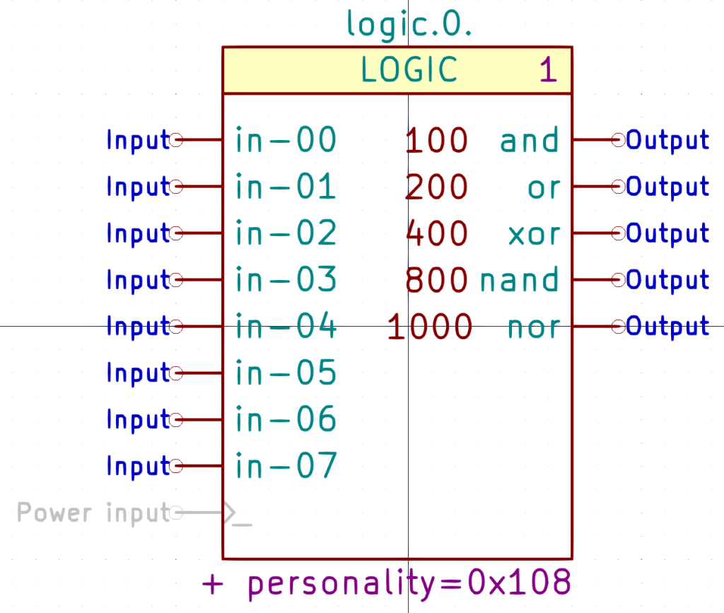
DEF LOGIC logic.0. 0 20 N Y 1 F N |
|
F0 "logic.0." 0 650 50 H V C CNN |
|
F1 "LOGIC" 0 550 50 H V C CNN |
|
F2 "" 350 -200 50 H I C CNN |
|
F3 "" 350 -200 50 H I C CNN |
|
F4 "1" 300 550 50 H V C CNN "StripAnno" |
|
F5 "+ personality=0x108" -50 -550 50 H V C CNN "LoadRT" |
|
DRAW |
|
T 0 -50 400 50 0 0 0 " 100" Normal 0 L C |
|
T 0 -50 300 50 0 0 0 " 200" Normal 0 L C |
|
T 0 -50 200 50 0 0 0 " 400" Normal 0 L C |
|
T 0 -50 100 50 0 0 0 " 800" Normal 0 L C |
|
T 0 -50 0 50 0 0 0 1000 Normal 0 L C |
|
S 350 500 -400 600 0 1 0 f |
|
S -400 500 350 -500 1 1 0 N |
|
X in-00 1 -500 400 100 R 50 50 1 1 I |
|
X or 10 450 300 100 L 50 50 1 1 O |
|
X xor 11 450 200 100 L 50 50 1 1 O |
|
X nand 12 450 100 100 L 50 50 1 1 O |
|
X nor 13 450 0 100 L 50 50 1 1 O |
|
X _ 14 -500 -400 100 R 50 50 1 1 W NC |
|
X in-01 2 -500 300 100 R 50 50 1 1 I |
|
X in-02 3 -500 200 100 R 50 50 1 1 I |
|
X in-03 4 -500 100 100 R 50 50 1 1 I |
|
X in-04 5 -500 0 100 R 50 50 1 1 I |
|
X in-05 6 -500 -100 100 R 50 50 1 1 I |
|
X in-06 7 -500 -200 100 R 50 50 1 1 I |
|
X in-07 8 -500 -300 100 R 50 50 1 1 I |
|
X and 9 450 400 100 L 50 50 1 1 O |
|
ENDDRAW |
|
ENDDEF |
|
# |
|
# LOGITECH_GAMEPAD_GUF13A |
|
# |
|
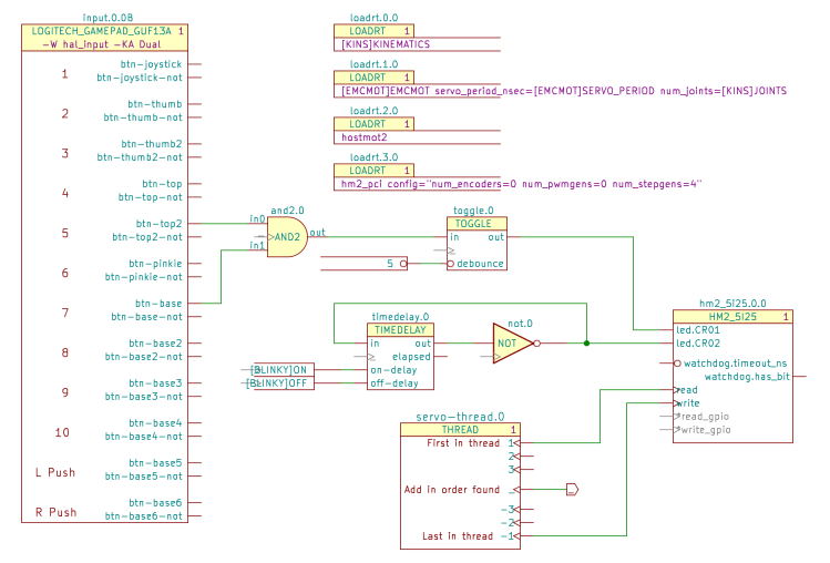
DEF LOGITECH_GAMEPAD_GUF13A input.0. 0 40 N Y 2 L N |
|
F0 "input.0." 0 1850 50 H V C CNN |
|
F1 "LOGITECH_GAMEPAD_GUF13A" -50 1750 50 H V C CNN |
|
F2 "" 5500 3600 50 H I C CNN |
|
F3 "" 5500 3600 50 H I C CNN |
|
F4 "1" 550 1750 50 H V C CNN "StripAnno" |
|
F5 "-W hal_input -KA Dual" -50 1650 50 H V C CNN "LoadUsr" |
|
DRAW |
|
T 0 -350 1400 59 0 2 1 1 Normal 0 L B |
|
T 0 -400 -1300 59 0 2 1 10 Normal 0 L B |
|
T 0 -350 1100 59 0 2 1 2 Normal 0 L B |
|
T 0 -350 800 59 0 2 1 3 Normal 0 L B |
|
T 0 -350 500 59 0 2 1 4 Normal 0 L B |
|
T 0 -350 200 59 0 2 1 5 Normal 0 L B |
|
T 0 -350 -100 59 0 2 1 6 Normal 0 L B |
|
T 0 -350 -400 59 0 2 1 7 Normal 0 L B |
|
T 0 -350 -700 59 0 2 1 8 Normal 0 L B |
|
T 0 -350 -1000 59 0 2 1 9 Normal 0 L B |
|
T 0 -550 -1600 59 0 2 1 "L Push" Normal 0 L B |
|
T 0 -550 -1900 59 0 2 1 "R Push" Normal 0 L B |
|
S -850 -1400 750 1600 1 1 0 N |
|
S 750 1600 -850 1800 1 1 0 f |
|
S -650 1600 600 1800 2 1 0 f |
|
S 600 -1950 -650 1600 2 1 0 N |
|
X abs-z-offset 1 -950 -500 100 R 0 50 1 1 I |
|
X abs-z-is-pos 11 850 -700 100 L 0 50 1 1 O |
|
X abs-z-is-neg 12 850 -800 100 L 0 50 1 1 O |
|
X abs-z-fuzz 13 -950 -800 100 R 0 50 1 1 I |
|
X abs-z-flat 14 -950 -700 100 R 0 50 1 1 I |
|
X abs-z-counts 15 850 -500 100 L 0 50 1 1 O |
|
X abs-y-scale 16 -950 -100 100 R 0 50 1 1 I |
|
X abs-y-position 17 850 -100 100 L 0 50 1 1 O |
|
X abs-y-offset 18 -950 0 100 R 0 50 1 1 I |
|
X abs-y-is-pos 28 850 -200 100 L 0 50 1 1 O |
|
X abs-hat0y-flat 37 -950 800 100 R 0 50 1 1 I |
|
X abs-rz-flat 38 -950 -1200 100 R 0 50 1 1 I |
|
X abs-rz-counts 39 850 -1000 100 L 0 50 1 1 O |
|
X abs-hat0y-scale 40 -950 900 100 R 0 50 1 1 I |
|
X abs-hat0y-position 41 850 900 100 L 0 50 1 1 O |
|
X abs-hat0y-offset 42 -950 1000 100 R 0 50 1 1 I |
|
X abs-hat0y-is-pos 43 850 800 100 L 0 50 1 1 O |
|
X abs-hat0y-is-neg 44 850 700 100 L 0 50 1 1 O |
|
X abs-hat0y-fuzz 45 -950 700 100 R 0 50 1 1 I |
|
X abs-rz-fuzz 46 -950 -1300 100 R 0 50 1 1 I |
|
X abs-hat0y-counts 47 850 1000 100 L 0 50 1 1 O |
|
X abs-hat0x-scale 48 -950 1400 100 R 0 50 1 1 I |
|
X abs-hat0x-position 49 850 1400 100 L 0 50 1 1 O |
|
X abs-hat0x-offset 50 -950 1500 100 R 0 50 1 1 I |
|
X abs-hat0x-is-pos 51 850 1300 100 L 0 50 1 1 O |
|
X abs-hat0x-is-neg 52 850 1200 100 L 0 50 1 1 O |
|
X abs-hat0x-fuzz 53 -950 1200 100 R 0 50 1 1 I |
|
X abs-hat0x-flat 54 -950 1300 100 R 0 50 1 1 I |
|
X abs-x-is-neg 55 850 200 100 L 0 50 1 1 O |
|
X abs-y-is-neg 56 850 -300 100 L 0 50 1 1 O |
|
X abs-y-fuzz 57 -950 -300 100 R 0 50 1 1 I |
|
X abs-y-flat 58 -950 -200 100 R 0 50 1 1 I |
|
X abs-y-counts 59 850 0 100 L 0 50 1 1 O |
|
X abs-x-scale 60 -950 400 100 R 0 50 1 1 I |
|
X abs-x-position 61 850 400 100 L 0 50 1 1 O |
|
X abs-x-offset 62 -950 500 100 R 0 50 1 1 I |
|
X abs-x-is-pos 63 850 300 100 L 0 50 1 1 O |
|
X abs-hat0x-counts 64 850 1500 100 L 0 50 1 1 O |
|
X abs-x-fuzz 65 -950 200 100 R 0 50 1 1 I |
|
X abs-x-flat 66 -950 300 100 R 0 50 1 1 I |
|
X abs-x-counts 67 850 500 100 L 0 50 1 1 O |
|
X abs-rz-scale 68 -950 -1100 100 R 0 50 1 1 I |
|
X abs-rz-position 69 850 -1100 100 L 0 50 1 1 O |
|
X abs-rz-offset 70 -950 -1000 100 R 0 50 1 1 I |
|
X abs-rz-is-pos 71 850 -1200 100 L 0 50 1 1 O |
|
X abs-rz-is-neg 72 850 -1300 100 L 0 50 1 1 O |
|
X abs-z-scale 8 -950 -600 100 R 0 50 1 1 I |
|
X abs-z-position 9 850 -600 100 L 0 50 1 1 O |
|
X btn-base4 10 700 -1200 100 L 0 50 2 1 O |
|
X btn-pinkie-not 19 700 -100 100 L 0 50 2 1 O |
|
X btn-base3-not 2 700 -1000 100 L 0 50 2 1 O |
|
X btn-top2-not 20 700 200 100 L 0 50 2 1 O |
|
X btn-top2 21 700 300 100 L 0 50 2 1 O |
|
X btn-top-not 22 700 500 100 L 0 50 2 1 O |
|
X btn-top 23 700 600 100 L 0 50 2 1 O |
|
X btn-thumb2-not 24 700 800 100 L 0 50 2 1 O |
|
X btn-thumb2 25 700 900 100 L 0 50 2 1 O |
|
X btn-thumb-not 26 700 1100 100 L 0 50 2 1 O |
|
X btn-thumb 27 700 1200 100 L 0 50 2 1 O |
|
X btn-pinkie 29 700 0 100 L 0 50 2 1 O |
|
X btn-base3 3 700 -900 100 L 0 50 2 1 O |
|
X btn-joystick-not 30 700 1400 100 L 0 50 2 1 O |
|
X btn-joystick 31 700 1500 100 L 0 50 2 1 O |
|
X btn-base6-not 32 700 -1900 100 L 0 50 2 1 O |
|
X btn-base6 33 700 -1800 100 L 0 50 2 1 O |
|
X btn-base5-not 34 700 -1600 100 L 0 50 2 1 O |
|
X btn-base5 35 700 -1500 100 L 0 50 2 1 O |
|
X btn-base4-not 36 700 -1300 100 L 0 50 2 1 O |
|
X btn-base2-not 4 700 -700 100 L 0 50 2 1 O |
|
X btn-base2 5 700 -600 100 L 0 50 2 1 O |
|
X btn-base-not 6 700 -400 100 L 0 50 2 1 O |
|
X btn-base 7 700 -300 100 L 0 50 2 1 O |
|
ENDDRAW |
|
ENDDEF |
|
# |
|
# MOTION |
|
# |
|
DEF MOTION motion. 0 40 N Y 1 F N |
|
F0 "motion." 0 1550 59 H V C CNN |
|
F1 "MOTION" 0 1450 50 H V C CNN |
|
F2 "" 0 350 50 H I C CNN |
|
F3 "" 0 350 50 H I C CNN |
|
F4 "1" 600 1450 50 H V C CNN "StripAnno" |
|
DRAW |
|
S -600 1400 650 -1100 1 1 0 N |
|
S 650 1400 -600 1500 1 1 0 f |
|
X feed-hold 1 -700 1000 100 R 0 50 1 0 I |
|
X coord-mode 10 750 950 100 L 0 50 1 0 O |
|
X distance-to-go 11 750 350 100 L 0 50 1 0 O |
|
X probe-input 12 -700 600 100 R 0 50 1 0 I |
|
X in-position 13 750 1300 100 L 0 50 1 0 O |
|
X adaptive-feed 14 -700 800 100 R 0 50 1 0 I |
|
X enable 15 -700 1300 100 R 0 50 1 0 I |
|
X digital-out-03 16 750 -750 100 L 0 50 1 0 O |
|
X digital-out-02 17 750 -650 100 L 0 50 1 0 O |
|
X digital-out-01 18 750 -550 100 L 0 50 1 0 O |
|
X digital-out-00 19 750 -450 100 L 0 50 1 0 O |
|
X homing-inhibit 2 -700 450 100 R 0 50 1 0 I |
|
X analog-out-00 20 750 -200 100 L 0 50 1 0 O |
|
X analog-out-01 21 750 -300 100 L 0 50 1 0 O |
|
X digital-in-03 22 -700 -750 100 R 0 50 1 0 I |
|
X digital-in-02 23 -700 -650 100 R 0 50 1 0 I |
|
X digital-in-01 24 -700 -550 100 R 0 50 1 0 I |
|
X analog-in-00 25 -700 -200 100 R 0 50 1 0 I |
|
X analog-in-01 26 -700 -300 100 R 0 50 1 0 I |
|
X digital-in-00 27 -700 -450 100 R 0 50 1 0 I |
|
X feed-inhibit 3 -700 900 100 R 0 50 1 0 I |
|
X on-soft-limit 30 750 -50 100 L 0 50 1 0 O |
|
X requested-vel 31 750 500 100 L 0 50 1 0 O |
|
X teleop-mode 32 750 750 100 L 0 50 1 0 O |
|
X motion-type 4 750 1100 100 L 0 50 1 0 O |
|
X motion-enabled 5 750 1200 100 L 0 50 1 0 O |
|
X offset-limited 6 750 100 100 L 0 50 1 0 O |
|
X current-vel 7 750 600 100 L 0 50 1 0 O |
|
X coord-error 8 750 850 100 L 0 50 1 0 O |
|
X offset-active 9 750 200 100 L 0 50 1 0 O |
|
X /motion-controller 28 -700 -1000 100 R 50 50 1 1 W C |
|
X /motion-command-handler 29 -700 -900 100 R 50 50 1 1 W C |
|
ENDDRAW |
|
ENDDEF |
|
# |
|
# MUX2 |
|
# |
|
DEF MUX2 mux2. 0 20 N Y 1 F N |
|
F0 "mux2." 0 300 50 H V C CNN |
|
F1 "MUX2" 0 200 50 H V C CNN |
|
F2 "" 350 -150 50 H I C CNN |
|
F3 "" 350 -150 50 H I C CNN |
|
F4 "+" 0 0 50 H I C CNN "LoadRT" |
|
DRAW |
|
S -150 150 150 -250 0 1 0 N |
|
S 150 150 -150 250 0 1 0 f |
|
X in0 1 -250 100 100 R 50 50 1 1 I |
|
X in1 2 -250 0 100 R 50 50 1 1 I |
|
X sel 3 -250 -200 100 R 50 50 1 1 I |
|
X out 4 250 100 100 L 50 50 1 1 O |
|
X _ 5 -250 -100 100 R 50 50 1 1 W NC |
|
ENDDRAW |
|
ENDDEF |
|
# |
|
# MUX4 |
|
# |
|
DEF MUX4 mux4. 0 20 N Y 1 F N |
|
F0 "mux4." 0 450 50 H V C CNN |
|
F1 "MUX4" 0 350 50 H V C CNN |
|
F2 "" 400 -100 50 H I C CNN |
|
F3 "" 400 -100 50 H I C CNN |
|
F4 "+" 0 0 50 H I C CNN "LoadRT" |
|
DRAW |
|
S 150 300 -150 400 0 1 0 f |
|
S -150 300 150 -400 1 1 0 N |
|
X in0 1 -250 250 100 R 50 50 1 1 I |
|
X in1 2 -250 150 100 R 50 50 1 1 I |
|
X in2 3 -250 50 100 R 50 50 1 1 I |
|
X in3 4 -250 -50 100 R 50 50 1 1 I |
|
X sel0 5 -250 -250 100 R 50 50 1 1 I |
|
X sel1 6 -250 -350 100 R 50 50 1 1 I |
|
X out 7 250 250 100 L 50 50 1 1 O |
|
X _ 8 -250 -150 100 R 50 50 1 1 W NC |
|
ENDDRAW |
|
ENDDEF |
|
# |
|
# MUX8 |
|
# |
|
DEF MUX8 mux8. 0 20 N Y 1 F N |
|
F0 "mux8." 0 750 50 H V C CNN |
|
F1 "MUX8" 0 650 50 H V C CNN |
|
F2 "" 350 -100 50 H I C CNN |
|
F3 "" 350 -100 50 H I C CNN |
|
F4 "+" 0 0 50 H I C CNN "LoadRT" |
|
DRAW |
|
S 150 600 -150 700 0 1 0 f |
|
S -150 600 150 -600 1 1 0 N |
|
X in0 1 -250 550 100 R 50 50 1 1 I |
|
X sel1 10 -250 -450 100 R 50 50 1 1 I |
|
X sel2 11 -250 -550 100 R 50 50 1 1 I |
|
X _ 12 -250 -250 100 R 50 50 1 1 W NC |
|
X in1 2 -250 450 100 R 50 50 1 1 I |
|
X in2 3 -250 350 100 R 50 50 1 1 I |
|
X in3 4 -250 250 100 R 50 50 1 1 I |
|
X in4 5 -250 150 100 R 50 50 1 1 I |
|
X in5 6 -250 50 100 R 50 50 1 1 I |
|
X in6 7 -250 -50 100 R 50 50 1 1 I |
|
X out 7 250 550 100 L 50 50 1 1 O |
|
X in7 8 -250 -150 100 R 50 50 1 1 I |
|
X sel0 9 -250 -350 100 R 50 50 1 1 I |
|
ENDDRAW |
|
ENDDEF |
|
# |
|
# NOT |
|
# |
|
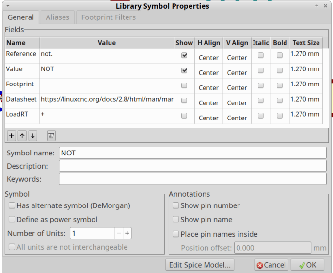
DEF NOT not. 0 0 N N 1 F N |
|
F0 "not." 100 150 50 H V C CNN |
|
F1 "NOT" 0 0 50 H V C CNN |
|
F2 "" 350 -250 50 H I C CNN |
|
F3 "" 350 -250 50 H I C CNN |
|
F4 "+" 0 0 50 H I C CNN "LoadRT" |
|
DRAW |
|
C 225 0 25 0 1 0 f |
|
P 4 1 0 10 -100 150 -100 -150 200 0 -100 150 f |
|
X in 1 -250 0 150 R 50 50 1 1 I |
|
X out 2 450 0 197 L 50 50 1 1 O |
|
X _ 3 -200 -100 100 R 50 50 1 1 W NC |
|
ENDDRAW |
|
ENDDEF |
|
# |
|
# OR2 |
|
# |
|
DEF OR2 or2. 0 0 N N 1 F N |
|
F0 "or2." 0 200 50 H V C CNN |
|
F1 "OR2" 0 0 50 H V C CNN |
|
F2 "" 50 0 50 H I C CNN |
|
F3 "" 50 0 50 H I C CNN |
|
F4 "+" 0 0 50 H I C CNN "LoadRT" |
|
DRAW |
|
A -360 0 258 354 -354 1 1 10 N -150 150 -150 -150 |
|
A -47 -52 204 150 837 1 1 10 f 150 0 -24 150 |
|
A -47 52 204 -150 -837 1 1 10 f 150 0 -24 -150 |
|
P 2 1 1 10 -150 -150 -25 -150 f |
|
P 2 1 1 10 -150 150 -25 150 f |
|
P 12 1 1 -1000 -25 150 -150 150 -150 150 -140 134 -119 89 -106 41 -103 -10 -109 -59 -125 -107 -150 -150 -150 -150 -25 -150 f |
|
X in0 1 -300 100 177 R 50 50 1 1 I |
|
X in1 2 -300 -100 177 R 50 50 1 1 I |
|
X out 3 300 0 150 L 50 50 1 1 O |
|
X _ 4 -200 0 100 R 50 50 1 1 W NC |
|
ENDDRAW |
|
ENDDEF |
|
# |
|
# PARAMETER |
|
# |
|
DEF PARAMETER parameter. 0 0 N N 1 F N |
|
F0 "parameter." 0 100 50 H I C CNN |
|
F1 "PARAMETER" 200 0 50 H V R CNN |
|
F2 "" 300 0 50 H I C CNN |
|
F3 "" 300 0 50 H I C CNN |
|
DRAW |
|
P 4 1 1 0 -350 50 300 50 300 -50 -350 -50 N |
|
X out 1 400 0 154 L 50 50 1 0 O I |
|
ENDDRAW |
|
ENDDEF |
|
# |
|
# PID |
|
# |
|
DEF PID pid.0. 0 40 N Y 1 F N |
|
F0 "pid.0." 0 1400 50 H V C CNN |
|
F1 "PID" 0 1300 50 H V C CNN |
|
F2 "" 750 600 50 H I C CNN |
|
F3 "" 750 600 50 H I C CNN |
|
F4 "1" 600 1300 50 H V C CNN "StripAnno" |
|
DRAW |
|
S -550 1250 650 -1750 0 0 0 N |
|
S 650 1250 -550 1350 0 0 0 f |
|
X do-pid-calcs 1 -650 -1650 100 R 0 50 1 0 I C |
|
X maxerrorD 10 -650 -1000 100 R 0 50 1 0 I |
|
X maxerror 11 -650 -900 100 R 0 50 1 0 I |
|
X maxcmdDDD 12 -650 -1450 100 R 0 50 1 0 I |
|
X maxcmdDD 13 -650 -1350 100 R 0 50 1 0 I |
|
X maxcmdD 14 -650 -1250 100 R 0 50 1 0 I |
|
X index-enable 15 -650 600 100 R 0 50 1 0 I |
|
X Igain 16 -650 100 100 R 0 50 1 0 I |
|
X FF3 17 -650 -450 100 R 0 50 1 0 I |
|
X FF2 18 -650 -350 100 R 0 50 1 0 I |
|
X FF1 19 -650 -250 100 R 0 50 1 0 I |
|
X command 2 -650 950 100 R 0 50 1 0 I |
|
X FF0 20 -650 -150 100 R 0 50 1 0 I |
|
X feedback-deriv 21 -650 1100 100 R 0 50 1 0 I |
|
X feedback 22 -650 1200 100 R 0 50 1 0 I |
|
X error-previous-target 23 -650 -650 100 R 0 50 1 0 I |
|
X error 24 750 850 100 L 0 50 1 0 O |
|
X enable 25 -650 700 100 R 0 50 1 0 I |
|
X Dgain 26 -650 0 100 R 0 50 1 0 I |
|
X deadband 27 -650 350 100 R 0 50 1 0 I |
|
X command-deriv 28 -650 850 100 R 0 50 1 0 I |
|
X bias 29 -650 450 100 R 0 50 1 0 I |
|
X saturated-s 3 750 600 100 L 0 50 1 0 O |
|
X saturated-count 4 750 500 100 L 0 50 1 0 O |
|
X saturated 5 750 700 100 L 0 50 1 0 O |
|
X Pgain 6 -650 200 100 R 0 50 1 0 I |
|
X output 7 750 950 100 L 0 50 1 0 O |
|
X maxoutput 8 -650 -750 100 R 0 50 1 0 I |
|
X maxerrorI 9 -650 -1100 100 R 0 50 1 0 I |
|
ENDDRAW |
|
ENDDEF |
|
# |
|
# SCALE |
|
# |
|
DEF SCALE scale. 0 20 N Y 1 F N |
|
F0 "scale." 0 300 50 H V C CNN |
|
F1 "SCALE" 0 200 50 H V C CNN |
|
F2 "" 550 -350 50 H I C CNN |
|
F3 "" 550 -350 50 H I C CNN |
|
F4 "+" 0 0 50 H I C CNN "LoadRT" |
|
DRAW |
|
S 150 150 -150 250 0 1 0 f |
|
S -150 150 150 -250 1 1 0 N |
|
X in 1 -250 100 100 R 50 50 1 1 I |
|
X gain 2 -250 -100 100 R 50 50 1 1 I |
|
X offset 3 -250 -200 100 R 50 50 1 1 I |
|
X out 4 250 100 100 L 50 50 1 1 O |
|
X _ 5 -250 0 100 R 50 50 1 1 W NC |
|
ENDDRAW |
|
ENDDEF |
|
# |
|
# SPINDLE |
|
# |
|
DEF SPINDLE spindle.0. 0 40 N Y 1 F N |
|
F0 "spindle.0." -50 900 50 H V C CNN |
|
F1 "SPINDLE" -50 800 50 H V C CNN |
|
F2 "" -50 100 50 H I C CNN |
|
F3 "" -50 100 50 H I C CNN |
|
F4 "1" 550 800 50 H V C CNN "StripAnno" |
|
DRAW |
|
S -650 750 600 -1000 1 1 0 N |
|
S 600 750 -650 850 1 1 0 f |
|
X at-speed 1 -750 -650 100 R 0 50 1 1 I |
|
X index-enable 10 -750 200 100 R 0 50 1 1 B |
|
X amp-fault-in 11 -750 -200 100 R 0 50 1 1 I |
|
X speed-out-abs 12 700 -700 100 L 0 50 1 1 O |
|
X speed-out-rps-abs 13 700 -900 100 L 0 50 1 1 O |
|
X speed-out-rps 14 700 -800 100 L 0 50 1 1 O |
|
X speed-cmd-rps 15 700 -450 100 L 0 50 1 1 O |
|
X orient-mode 16 700 -200 100 L 0 50 1 1 O |
|
X orient-angle 17 700 -100 100 L 0 50 1 1 O |
|
X speed-in 18 -750 -550 100 R 0 50 1 1 I |
|
X revs 19 -750 -300 100 R 0 50 1 1 I |
|
X speed-out 2 700 -550 100 L 0 50 1 1 O |
|
X orient-fault 20 -750 -50 100 R 0 50 1 1 I |
|
X is-oriented 21 -750 50 100 R 0 50 1 1 I |
|
X orient 3 700 0 100 L 0 50 1 1 O |
|
X locked 4 700 200 100 L 0 50 1 1 O |
|
X reverse 5 700 450 100 L 0 50 1 1 O |
|
X on 6 700 650 100 L 0 50 1 1 O |
|
X forward 7 700 550 100 L 0 50 1 1 O |
|
X brake 8 700 350 100 L 0 50 1 1 O |
|
X inhibit 9 -750 650 100 R 0 50 1 1 I |
|
ENDDRAW |
|
ENDDEF |
|
# |
|
# THREAD |
|
# |
|
DEF THREAD name-thread. 0 40 N Y 1 F N |
|
F0 "name-thread." 0 550 59 H V C CNN |
|
F1 "THREAD" 0 450 50 H V C CNN |
|
F2 "" 100 100 50 H I C CNN |
|
F3 "" 100 100 50 H I C CNN |
|
F4 "1" 400 450 50 H V C CNN "StripAnno" |
|
DRAW |
|
T 0 300 350 50 0 0 0 "First in thread" Normal 0 R C |
|
T 0 250 -350 50 0 0 0 "Last in thread" Normal 0 R C |
|
T 0 300 0 50 0 0 0 "Sorted by ref" Normal 0 R C |
|
S -450 400 450 500 0 1 0 f |
|
S 450 -450 -450 400 0 1 0 N |
|
X 1 1 550 350 100 L 0 50 1 0 w C |
|
X 2 2 550 250 100 L 0 50 1 0 w C |
|
X 3 3 550 150 100 L 0 50 1 0 w C |
|
X _ 4 550 0 100 L 0 50 1 0 w C |
|
X -3 5 550 -150 100 L 0 50 1 0 w C |
|
X -2 6 550 -250 100 L 0 50 1 0 w C |
|
X -1 7 550 -350 100 L 0 50 1 0 w C |
|
ENDDRAW |
|
ENDDEF |
|
# |
|
# TIMEDELAY |
|
# |
|
DEF TIMEDELAY timedelay. 0 20 N Y 1 F N |
|
F0 "timedelay." 0 350 50 H V C CNN |
|
F1 "TIMEDELAY" 0 250 50 H V C CNN |
|
F2 "" 0 150 50 H I C CNN |
|
F3 "" 0 150 50 H I C CNN |
|
F4 "+" 0 0 50 H I C CNN "LoadRT" |
|
DRAW |
|
S 250 200 -250 300 0 1 0 f |
|
S -250 200 250 -200 1 1 0 N |
|
X in 1 -350 150 100 R 50 50 1 1 I |
|
X on-delay 2 -350 -50 100 R 50 50 1 1 I |
|
X off-delay 3 -350 -150 100 R 50 50 1 1 I |
|
X out 4 350 150 100 L 50 50 1 1 O |
|
X elapsed 5 350 50 100 L 50 50 1 1 O |
|
X _ 6 -350 50 100 R 50 50 1 1 W NC |
|
ENDDRAW |
|
ENDDEF |
|
# |
|
# TOGGLE |
|
# |
|
DEF TOGGLE toggle. 0 20 N Y 1 F N |
|
F0 "toggle." 0 300 50 H V C CNN |
|
F1 "TOGGLE" 0 200 50 H V C CNN |
|
F2 "" 300 -50 50 H I C CNN |
|
F3 "" 300 -50 50 H I C CNN |
|
F4 "+" 0 0 50 H I C CNN "LoadRT" |
|
DRAW |
|
S 250 150 -200 250 0 1 0 f |
|
S -200 150 250 -150 1 1 0 N |
|
X in 1 -300 100 100 R 50 50 1 1 I |
|
X out 2 350 100 100 L 50 50 1 1 O |
|
X debounce 4 -250 -100 100 R 50 50 1 1 I I |
|
X _ 5 -300 0 100 R 50 50 1 1 W NC |
|
ENDDRAW |
|
ENDDEF |
|
# |
|
# XOR2 |
|
# |
|
DEF XOR2 xor2. 0 0 N N 1 F N |
|
F0 "xor2." -50 200 50 H V C CNN |
|
F1 "XOR2" 25 0 50 H V C CNN |
|
F2 "" 0 0 50 H I C CNN |
|
F3 "" 0 0 50 H I C CNN |
|
F4 "+" 0 0 50 H I C CNN "LoadRT" |
|
DRAW |
|
A -385 0 258 354 -354 1 1 10 N -175 150 -175 -150 |
|
A -360 0 258 354 -354 1 1 10 N -150 150 -150 -150 |
|
A -47 -52 204 150 837 1 1 10 f 150 0 -24 150 |
|
A -47 52 204 -150 -837 1 1 10 f 150 0 -24 -150 |
|
P 2 1 1 10 -150 -150 -25 -150 f |
|
P 2 1 1 10 -150 150 -25 150 f |
|
P 12 1 1 -1000 -25 150 -150 150 -150 150 -140 134 -119 89 -106 41 -103 -10 -109 -59 -125 -107 -150 -150 -150 -150 -25 -150 f |
|
X in0 1 -350 100 228 R 50 50 1 1 I |
|
X in1 2 -350 -100 228 R 50 50 1 1 I |
|
X out 3 300 0 150 L 50 50 1 1 O |
|
X _ 4 -250 0 150 R 50 50 1 1 W NC |
|
ENDDRAW |
|
ENDDEF |
|
# |
|
#End Library |