Wiping down a tool or wiping up a mess with a small rag and then throwing it out simplifies cleanup:

Long ago, I applied scissors to old towels / t-shirts / whatever to get randomly sized squares, but when Mary began using rotary cutters for her sewing projects I immediately saw the light. A few times a year, I lower the scrap box level and restock the shop wipes boxes.
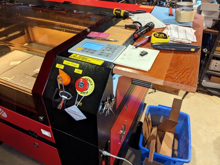
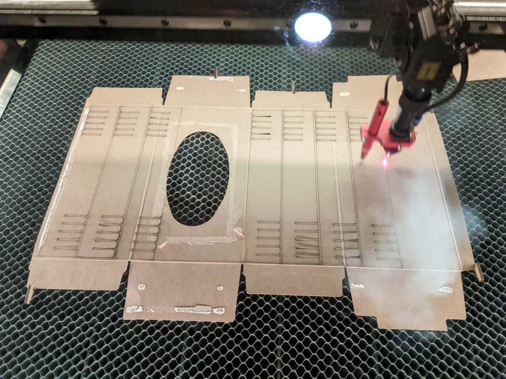
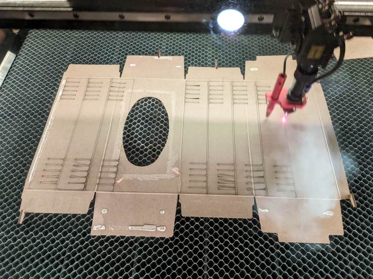
A laser cutter is even better:
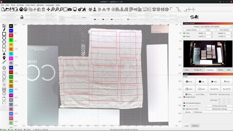
Flatten the rag on the honeycomb, drag a few rectangles into place, and fire the laser:

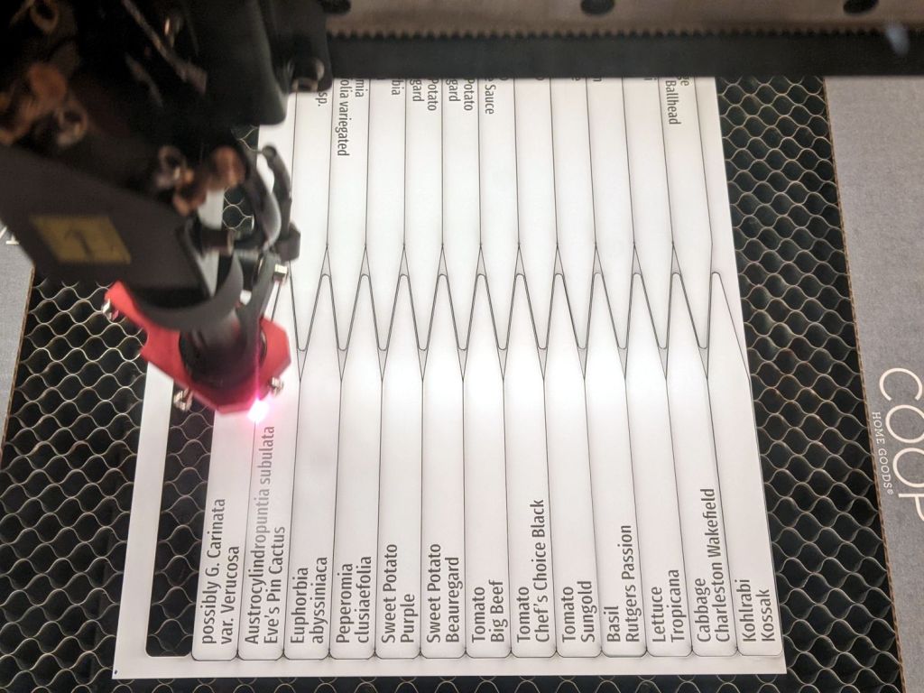
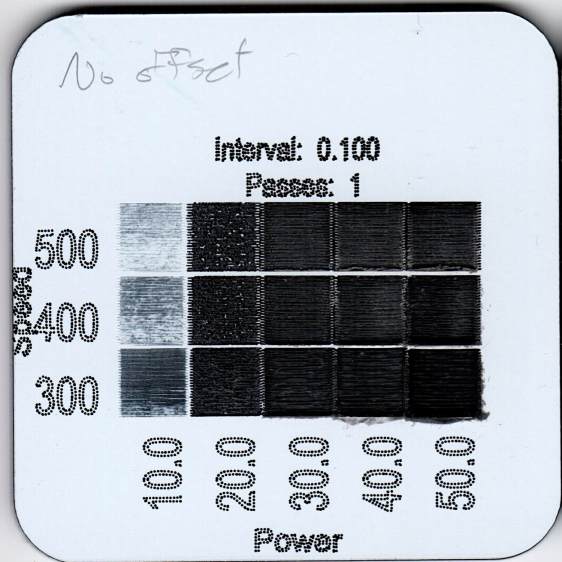
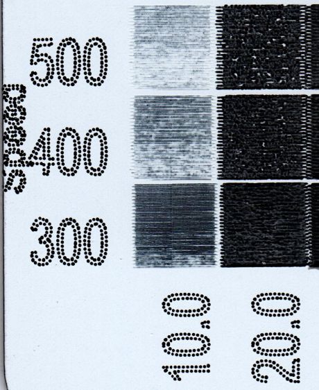
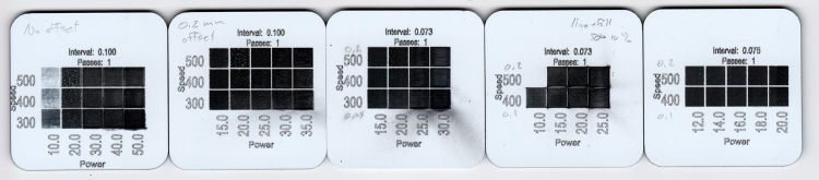
Something like 50 mm/s at 60% power works for all the fabrics I’ve tried, from worn-out towels and dead sweatpants to napkins and t-shirts. Thinner fabrics can be stacked, but wrinkles and seams get in the way of clean cuts.
Rounded-corner rectangles are easy enough to draw and the scrap cloths have different shapes, so I don’t see much point in saving a file with any specific layout. Your scrap box may be more orderly.
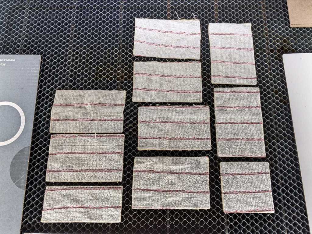
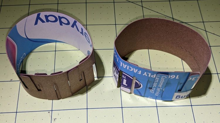
A clean cut lets the outer cloth just lift away:

The wipes give off a distinct smell of charred cloth, but running them through the clothes washer in a big mesh bag with everything else solves that problem.
Obviously, one couldn’t possibly justify a laser cutter to make shop wipes, but if you happen to have one just standing around, well …


