Ed Nisley's Blog: Shop notes, electronics, firmware, machinery, 3D printing, laser cuttery, and curiosities. Contents: 100% human thinking, 0% AI slop.
Tag: Improvements
Making the world a better place, one piece at a time
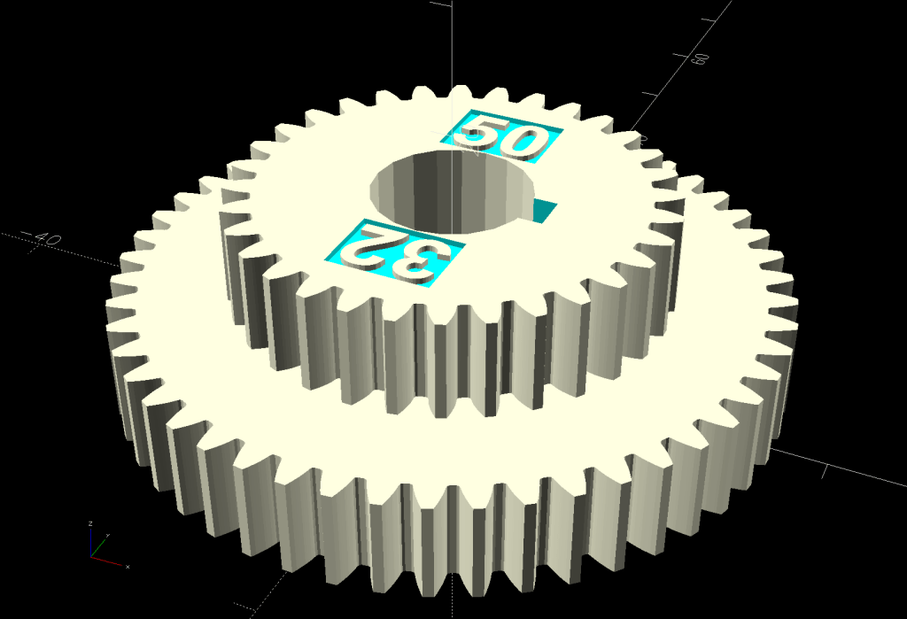
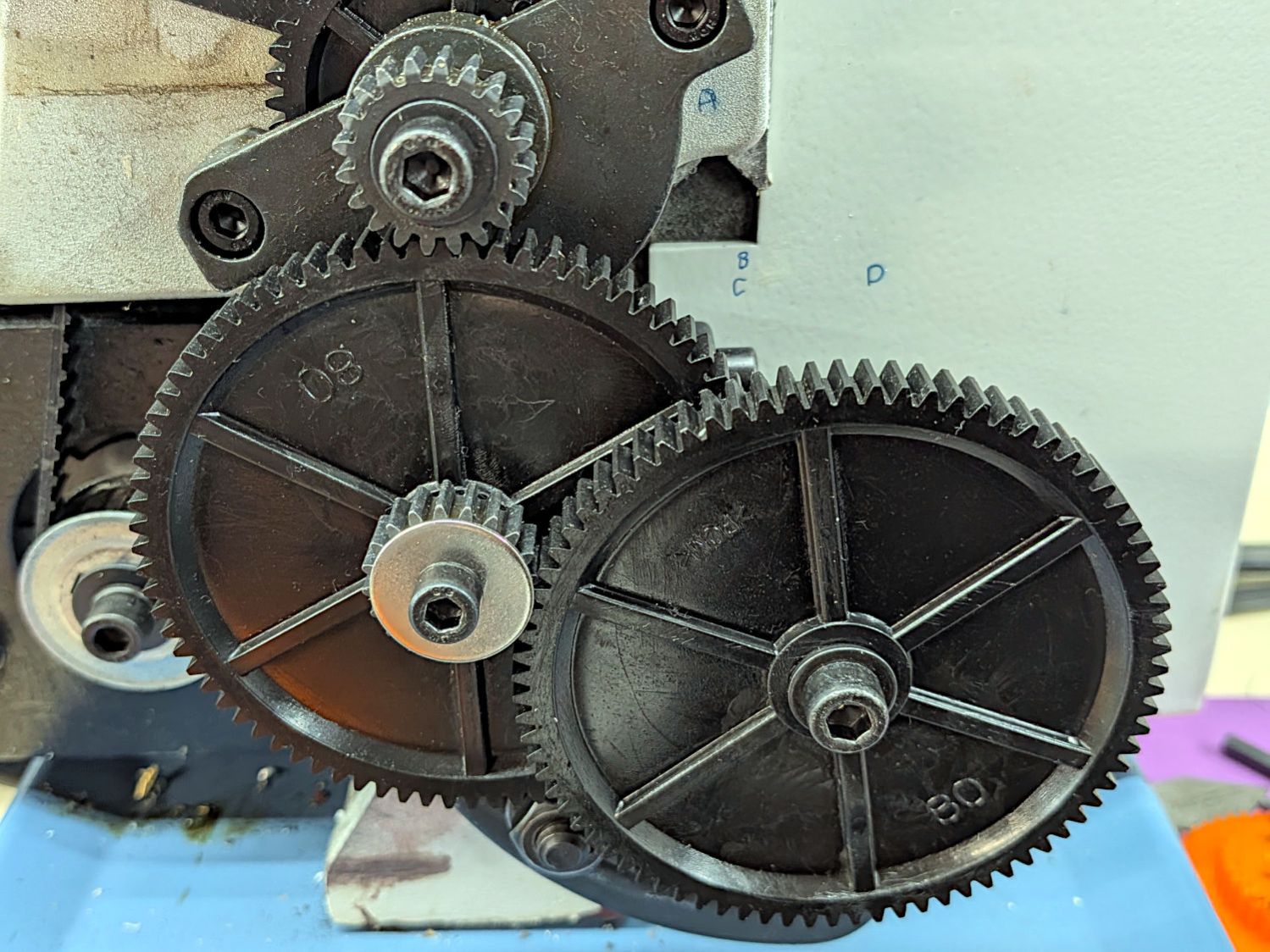
Before turning the PVC conduit to the proper diameter for the Shopvac hose adapter, I set up a 20-50-32-80 change gear train for a 100 TPI finish. While the urethane adhesive cured in the hose, I fed the BC gear pair into my change gear generator:
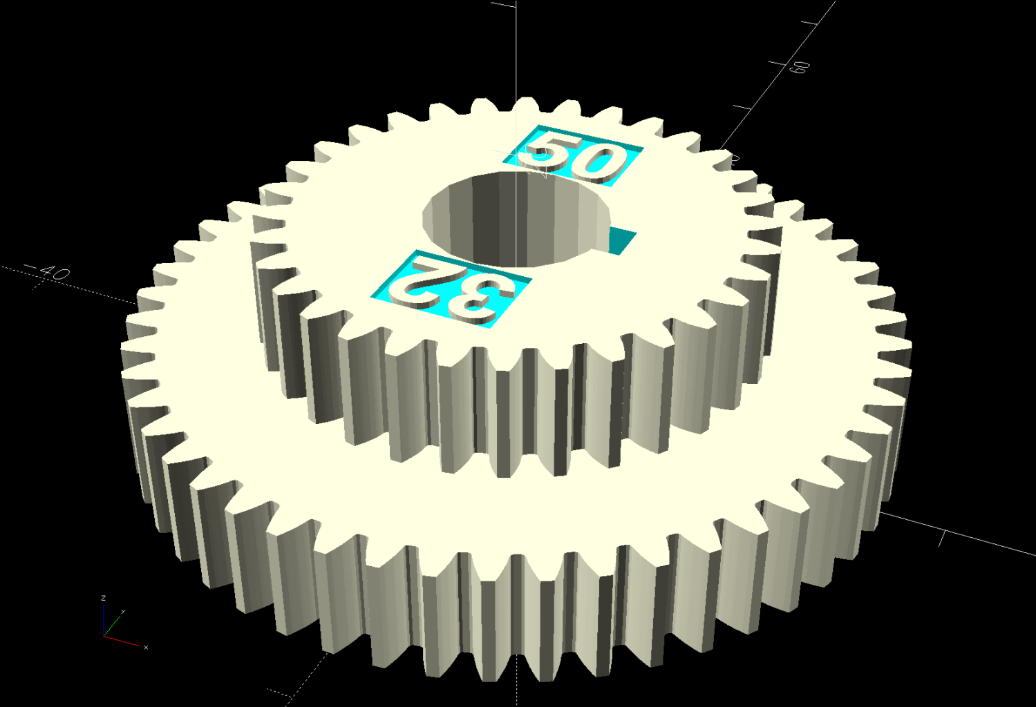
Mini-lathe stacked change gears – 32-50T – solid model
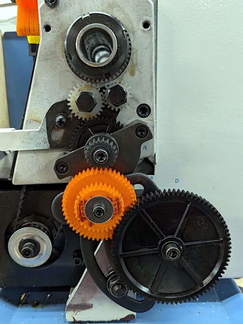
It’s ready for the next time I cut something down to size:
Mini-lathe 100 TPI change gears
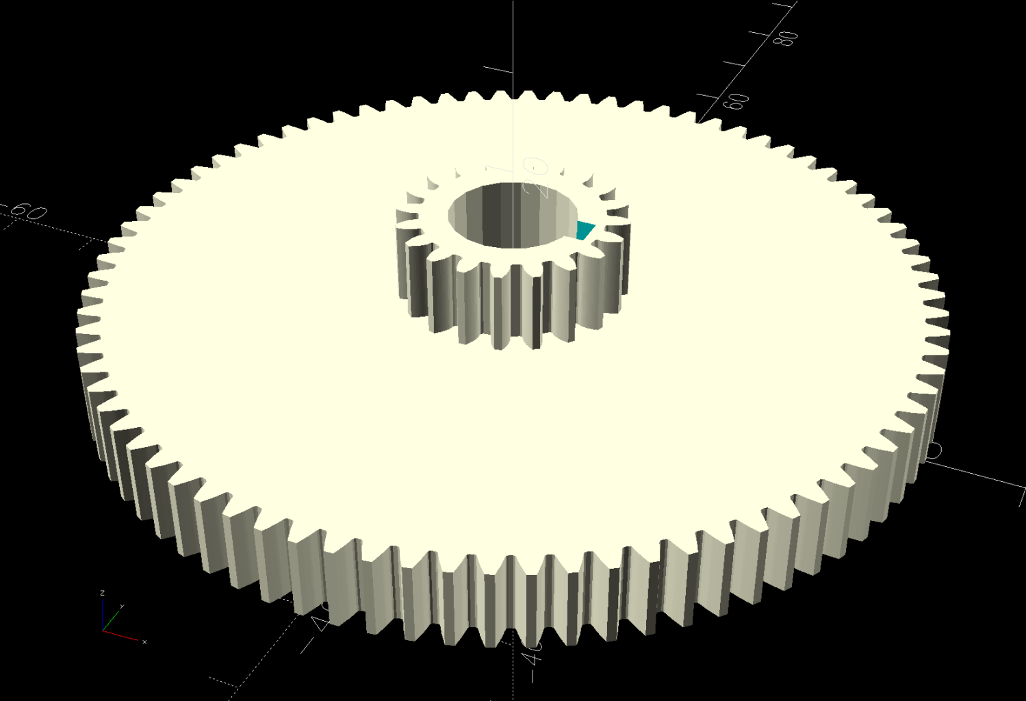
One reference suggests a 256 TPI finish for “general turning”, which works out to 20-80-20-80:
Mini-lathe stacked change gears – 20-80T – solid model
That’s just crazy talk, because the BC washer overlaps the D gear teeth:
Mini-lathe 256 TPI change gears
If all else fails and I really need a 256 TPI finish, lathes are pretty good at making washers.
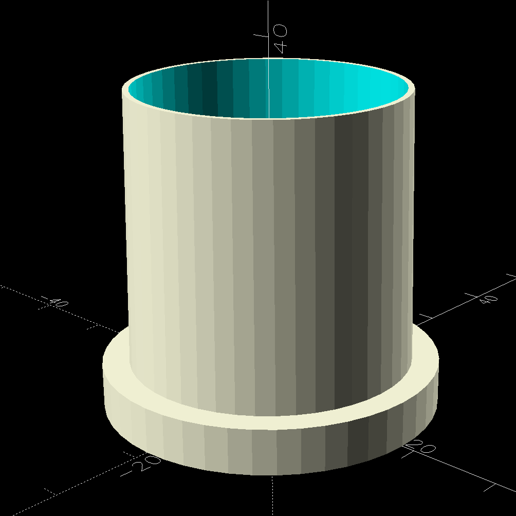
The tapered adapter drags the OpenSCAD code into the BOSL2 era:
Spiral Hose – 1.25in nozzle adapter – solid model
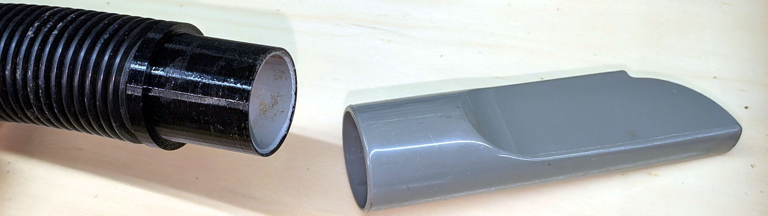
The ID of the hose determined the OD of the lathe-turned PVC tube inside the 3D printed adapter, so a straight pipe would just slide right into both parts.
It would be possible to skip the 3D printing and make the adapter from a single piece of PVC:
Turn one end of the conduit to fit the hose ID
Maneuver the lathe compound to the required 1.05° half-angle
Turn the taper to fit the crevice tool
Clean up the original OD between the two sections
Just turning the whole pipe to a smaller OD and sliding the taper on was definitely easier, particularly given the mini-lathe’s cramped quarters with the compound nearly parallel to the bed.
A generous helping of JB PlasticBonder urethane adhesive bonds the PVC pipe inside the vacuum hose and the tapered adapter.
The as-printed taper perfectly fits the crevice tool shown in the picture and is one wrap of electrical tape smaller than another crevice tool of “the same size”. The Finesse variable handles that situation, should it matter to you.
The OpenSCAD source code:
// Shopvac spiral hose to 1.25 in nozzle
// Ed Nisley - KE4ZNU
// 2026-07-25

include <BOSL2/std.scad>

Finesse = 0.2;             // [-0.5:0.1:0.5]

// PVC pipe liner final OD
PipeOD = 28.5;

/* [Hidden] */

NumSides = 4*3*4;
$fn=NumSides;

Protrusion = 0.1;           // make holes end cleanly
HoleWindage = 0.2;          // make holes large enough to fit

//----------------------
// Dimensions

TAPER_MIN = 0;
TAPER_MAX = 1;
TAPER_LENGTH = 2;

Tool = [30.0,31.1,30.0] + [Finesse,Finesse,0];

FlangeOD = 37.0;
FlangeLength = 5.0;

//render()
difference() {

    union() {
        cyl(FlangeLength,d=FlangeOD,anchor=BOTTOM) position(TOP)
          cyl(Tool[TAPER_LENGTH],d1=Tool[TAPER_MAX],d2=Tool[TAPER_MIN],anchor=BOTTOM);
      }

    down(Protrusion)
      cyl(2*Tool[TAPER_LENGTH] + FlangeLength,d=PipeOD + HoleWindage,anchor=BOTTOM);

}
Having just cleaned a bunch of gunk out of the bottom of the worm bin, we decided to try a layer of window screen to keep both gunk and worms out of the sump.
A roll of window screen Came With The House™, minus label or provenance, that felt like some sort of plastic, perhaps with a glass core.
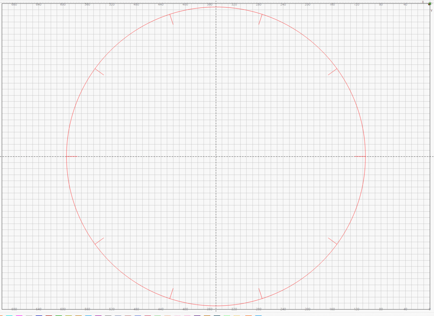
The bin has a 19-¼ inch = 488 mm ID with 10 thin support struts around the perimeter. Laying out a circle and cutting it accurately by hand seemed like a chore, even though the screen cut easily with ordinary scissors.
The diameter just barely fit on the laser’s 700×500 mm platform, so I laid it out in LightBurn:
Laser-cut window screen – LightBurn layout
For lack of anything smarter, I applied the same setting as for the faucet gasket material (30 mm/s at 25% of 60 W) and Fired The Laser.
As far as I could tell while the laser was trundling around the circle, absolutely nothing happened other than maybe burning off a coating with a little discoloration on either side of the path.
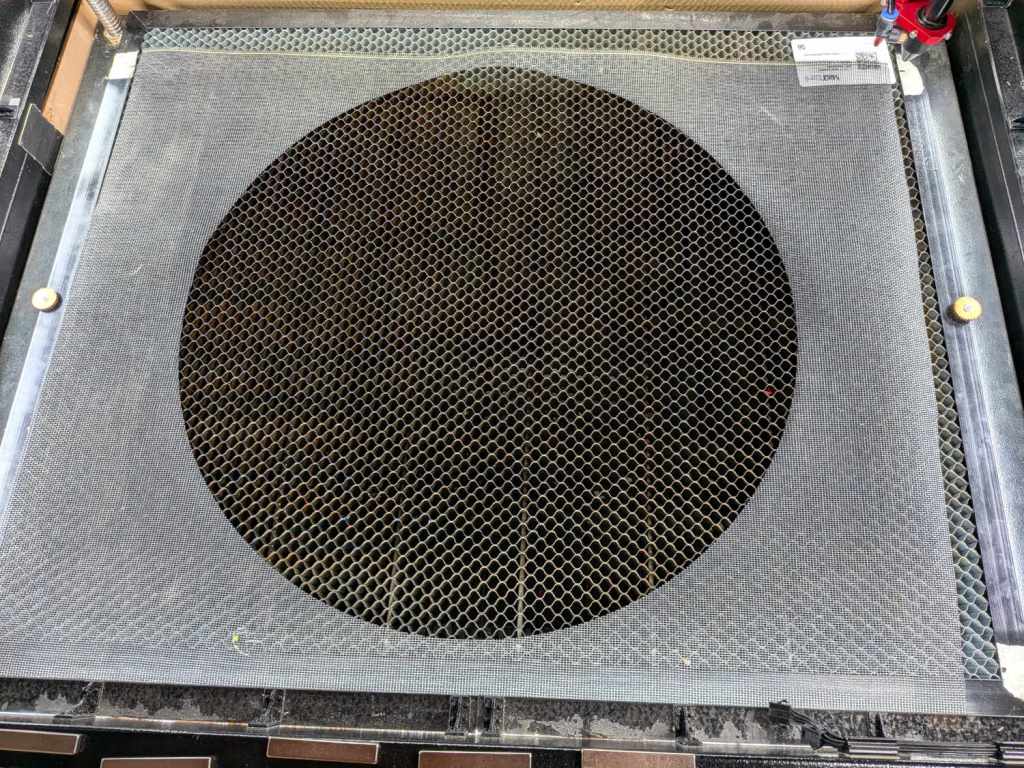
However, the circle lifted out with zero drama:
Laser-cut window screen
And was a perfect fit in the worm bin.
Color me surprised!
I have no pictures of the happy results, as all this happened in the few minutes between “We should try a screen”, dropping the cut screen in place, and reassembling the bin.
I think the screen would cut just as well with a higher speed. If the screen works and we need another, I’ll run a few tests first.
The idea came from the June/July 2026 Machinist’s Workshop, wherein I learned Dremel nuts / chucks fit on a 0.275 inch = 9/32 inch 40 TPI threaded body, drilled through 11/64 inch.
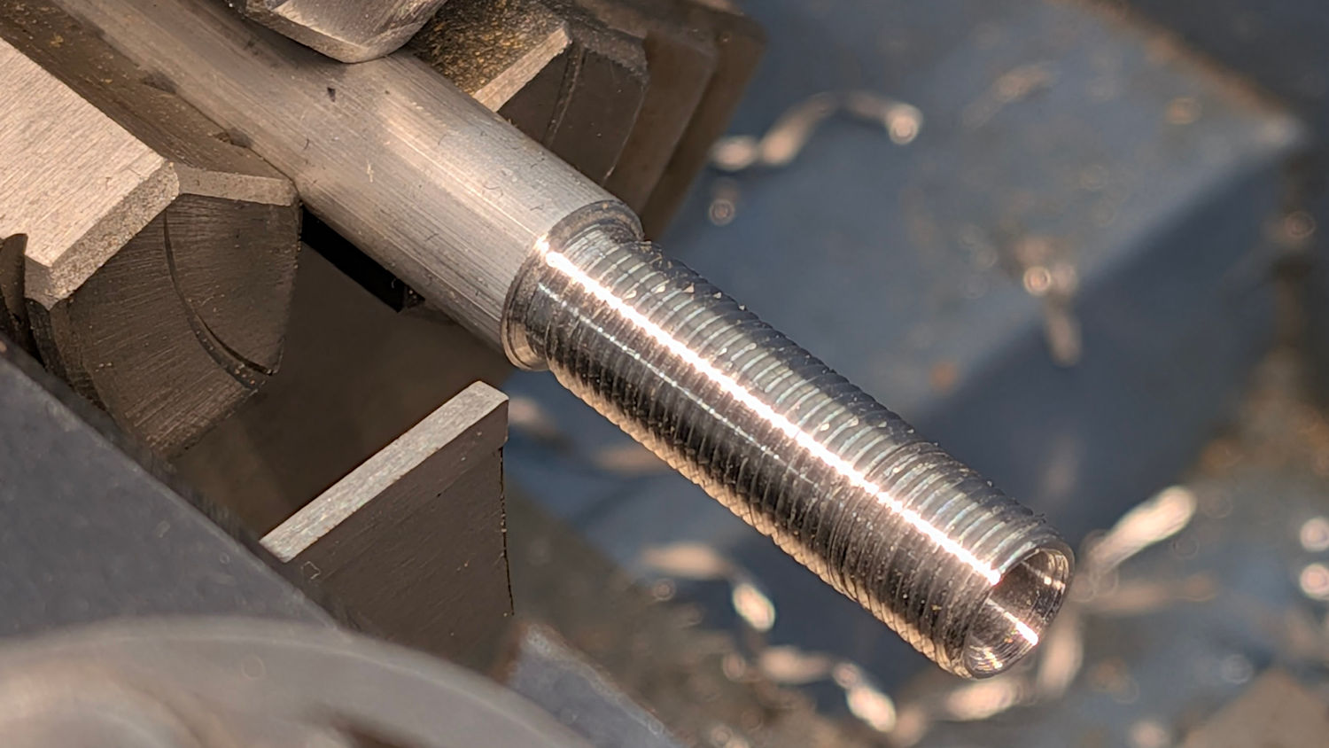
Making such a thing involved some pleasant lathe time:
Dremel Collet Chuck Handle – lathe work
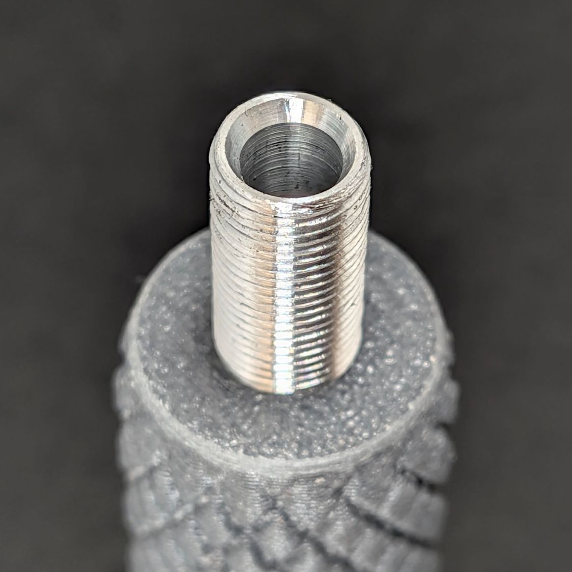
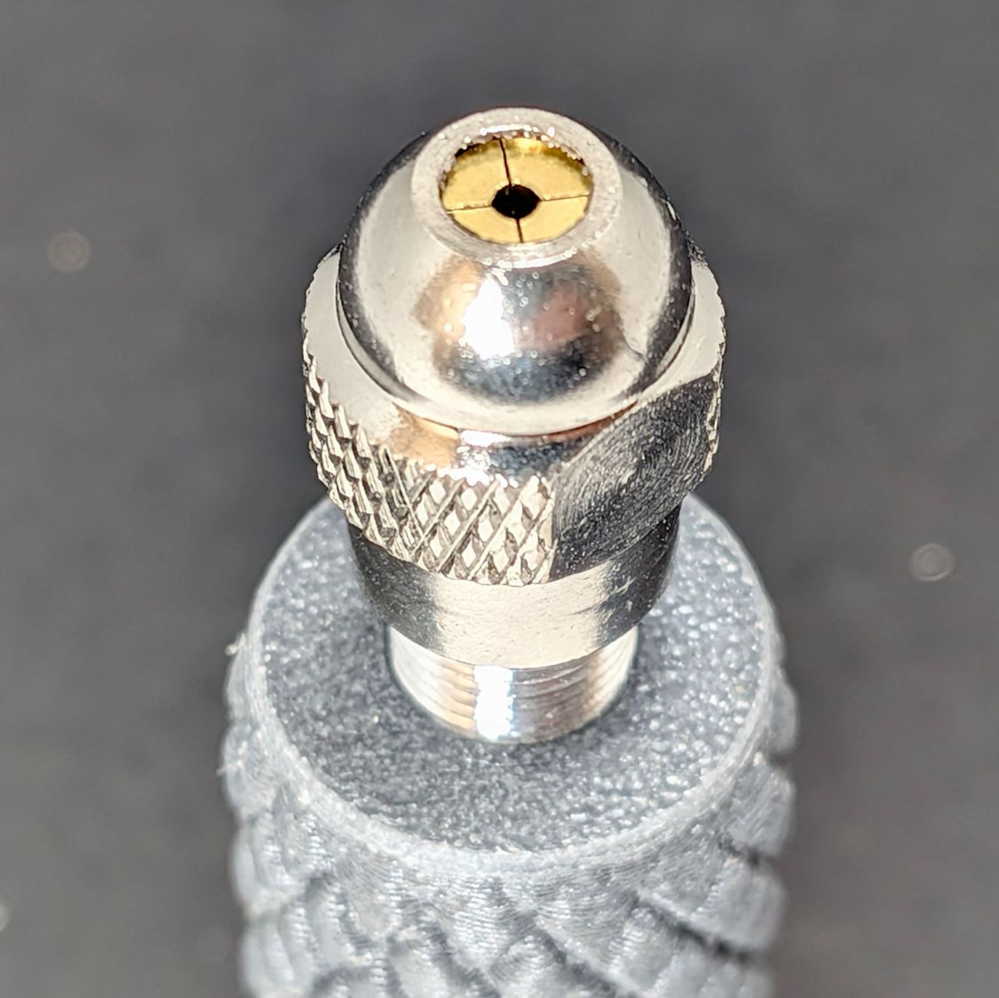
The business end of the body has a slight taper to (ideally) match the collets:
Dremel Collet Chuck Handle – threaded body recess
However, the collets have tapers ranging from 20° to 35°, so I defined a 60° center drill to be Good Enough™ and got a free taper while drilling the central hole.
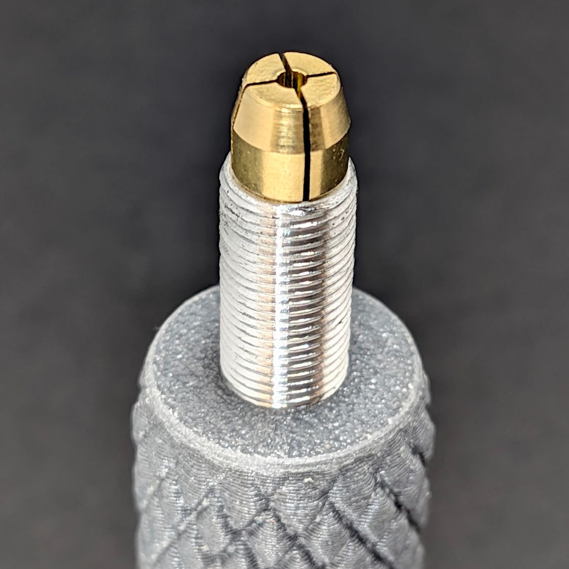
The collets sit in the taper:
Dremel Collet Chuck Handle – collet installed
Tightening the nut closes the collet:
Dremel Collet Chuck Handle – threaded body – nut installed
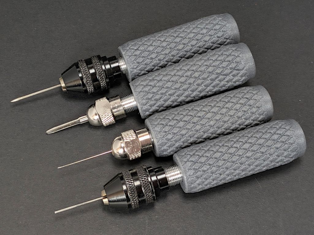
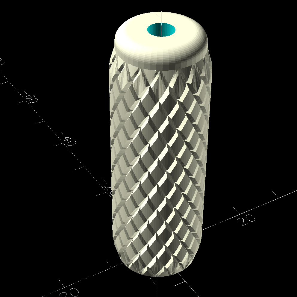
The article described a nicely turned wooden handle, but a somewhat uglier 3D printed handle is fine with me:
Dremel Collet Chuck Handle – solid model – top view
The variables match the threaded body to my fingers:
Protrusion = 0.1;           // make holes end cleanly
HoleWindage = 0.2;          // make holes large enough to fit

ShaftOD = 6.9;       // collet closer thread - 40 TPI 0.275 OD
ShaftID = 4.3;       //  … internal clearance

HandleOD = 15.0;
HandleLength = 45.0;
Knurling = "trunc_diamonds";
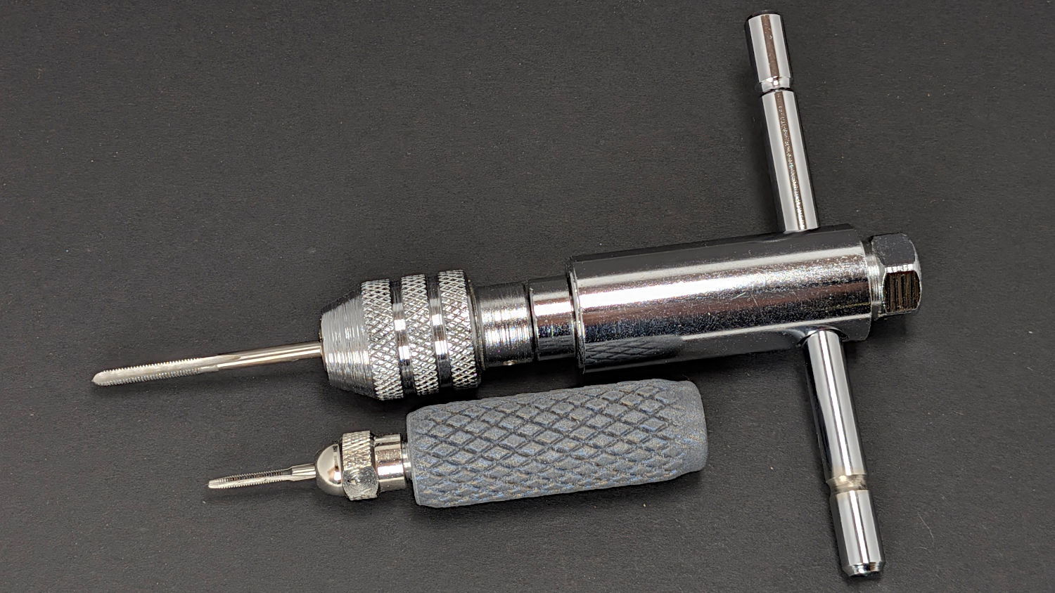
The motivation for all this was to put the smallest taps in a holder suitable for delicate jobs. The smallest chuck on my real tap driver bottoms out on an M3 tap and can’t grip the M2 tap:
Dremel Collet Chuck Handle – M3 vs M2 taps
I try very hard to not tap small holes, but sometimes you gotta do what you gotta do and now I’m better prepared.
Incidentally, the first threaded body I made absolutely did not fit the Dremel nuts. After eliminating everything else, I discovered I’d set up the lathe change gears with a 20-65-45 train, rather than the 20-65-50 train required for 40 TPI with the lathe’s 16 TPI leadscrew.
Protip: Even the best threading job (which I didn’t do on any of those things) can’t make a 36 TPI screw fit into a 40 TPI nut.
A new Gorilla Grip shower mat defeated the spring-loaded clip its predecessor dangled on between showers, so I applied a contour gauge to the shower stall, copied the shapes to paper, scanned them, then fit some curves:
Shower Mat Hanger – curve fitting
Combine the two to get a model of the shelf, subtract it from a rectangle, and produce a cardboard test piece:
Shower mat hanger – cardboard test 1
Put a hook on the bottom, a small bump on the top, and round the corners:
Shower Mat Hanger – LightBurn layout
Function-test a cardboard pair:
Shower mat hanger – cardboard test 2
They clear the hump along the edge and fit snugly across the front and sloping underside, so make an MVP from 6 mm acrylic:
Shower mat hanger – acrylic
Laser-cut acrylic may be too brittle for the job, but it gets the mat off the floor for drying and we’ll see how this works before doing anything more complex.
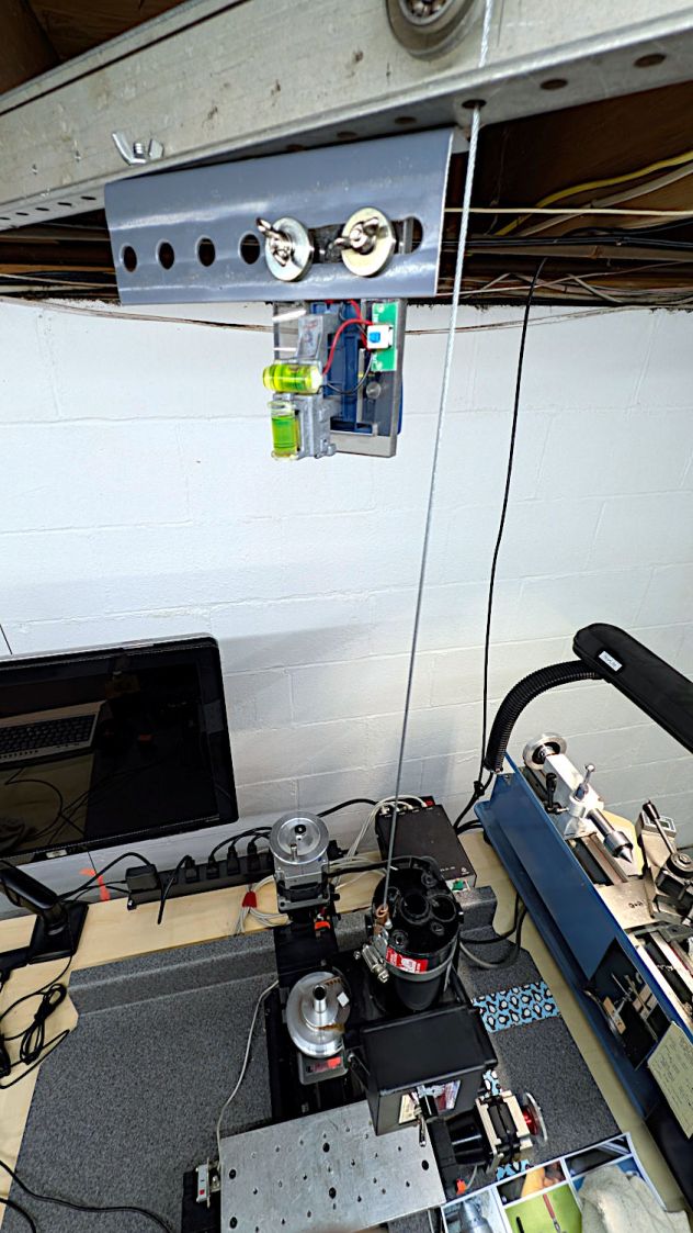
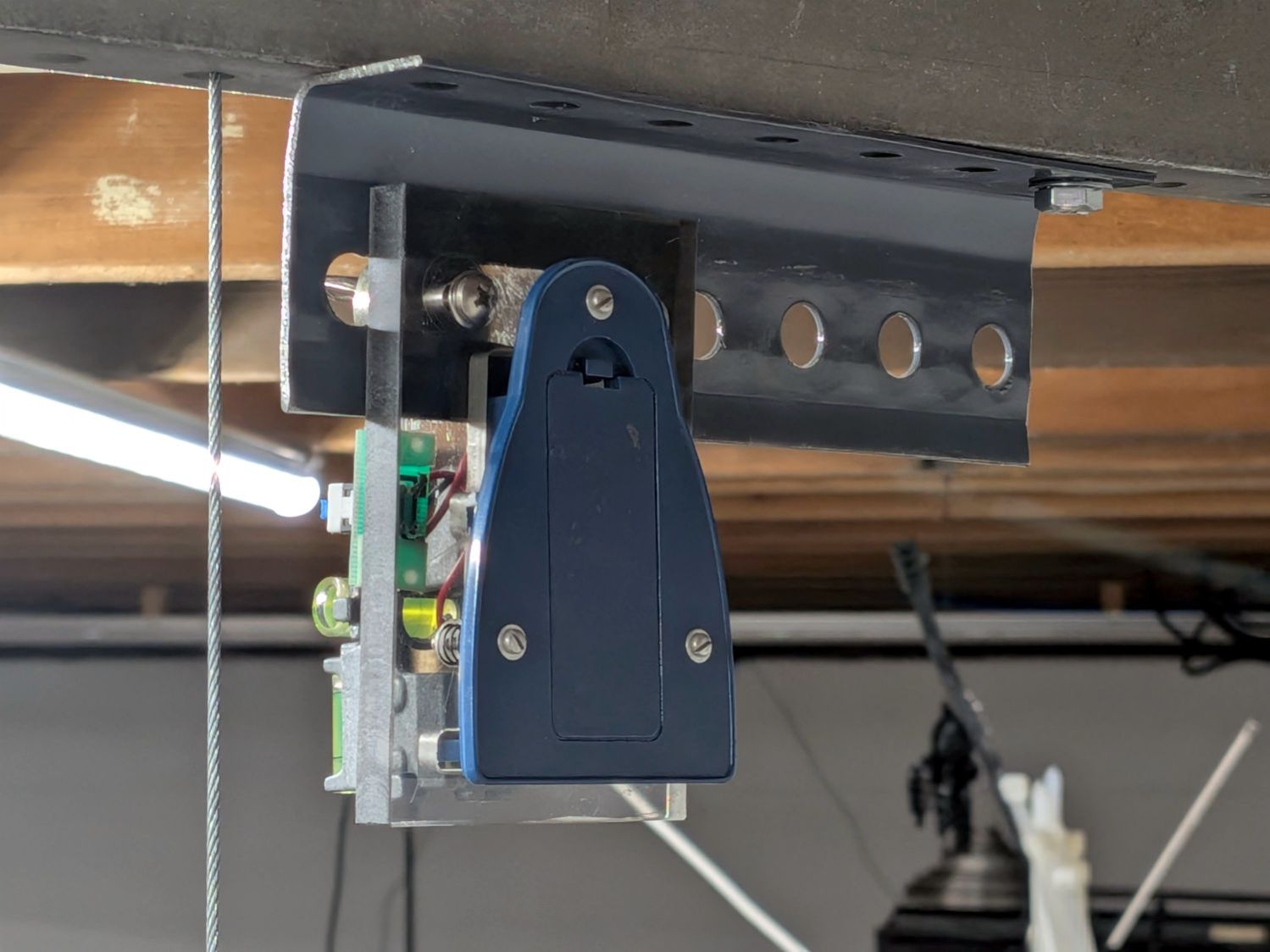
It’s (still) an upcycled laser line projector, minus the cylindrical lens stretching the dot into a line, running from a pair of AA alkaline cells:
Sherline laser aligner – rear view
The three small screws provide simpleminded angle adjustment, with the disadvantage of simultaneously moving the lens in the XY plane.
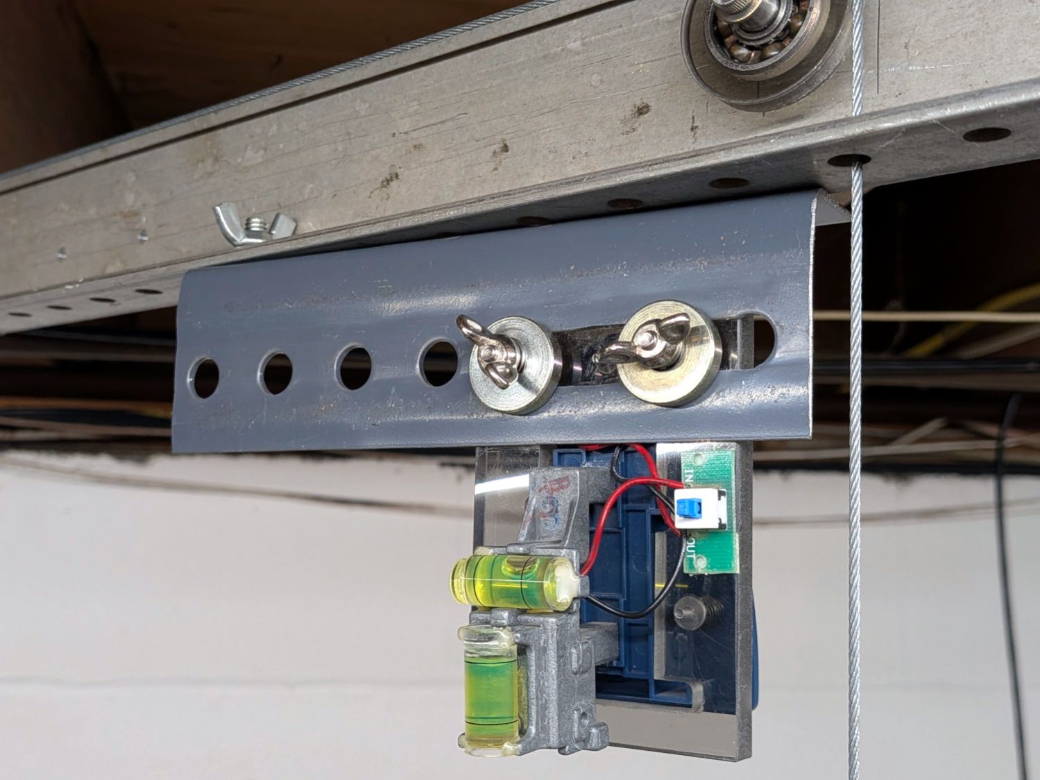
The upper bubble level shows it’s not at all vertical:
Sherline laser aligner – front view
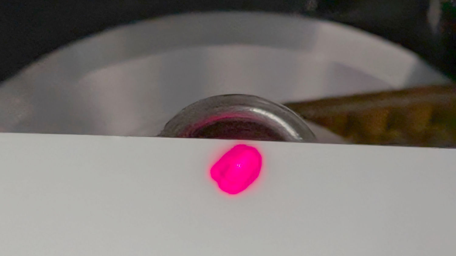
That’s because the beam must fall down the middle of the Sherline’s spindle bore:
Sherline laser aligner – beam at spindle top
Getting the alignment right requires a mirror on the tooling plate, which I will not attempt to photograph again, reflecting the beam upward through the spindle, where it will light up the bottom of the no-longer-a-line projector’s lens mount. When that happens, the projector is boresighted on the spindle, regardless of whether the tooling plate is perpendicular to the local gravitational field.
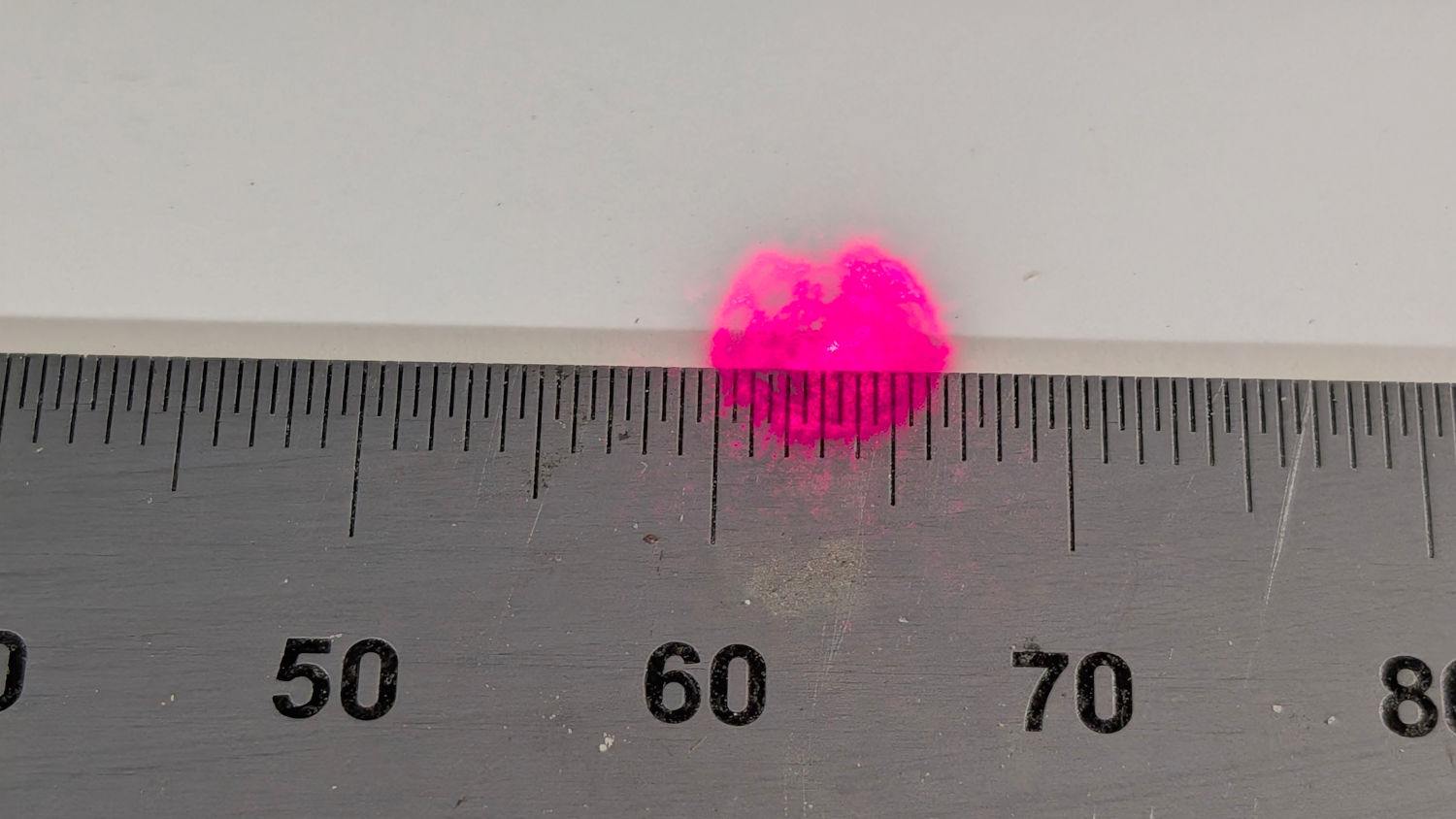
With the Z axis / spindle near the top of its travel, screwing the lens (mounted in a toolholder) onto the spindle produces a defocused beam on the tooling plate:
Sherline laser aligner – defocused spot – on scale
If the spot doesn’t look similarly round-ish, then the beam isn’t completely filling the entrance pupil of the lens and you must twiddle the projector’s angle / position until it does.
With that done, running the Z axis to put the lens about 30 mm above the plate produces a suitably teeny spot:
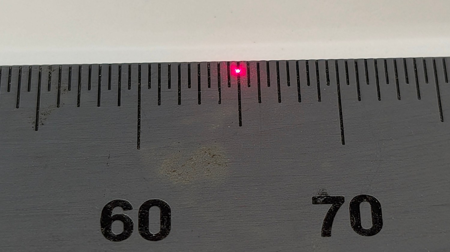
Sherline laser aligner – focused spot on scale
The Sherline’s previous home atop that same gray countertop had been firmly affixed to the basement wall, with the gantry and laser projector screwed to the floor joists: everything immovable. The countertop now sits atop a workbench not firmly affixed to anything: a good solid bump will likely knock the Sherline out of alignment with the beam.
How often that happens and how awful recovery will be remains to be seen. For now, It Just Works™ again.
Feeding Sherline aligner into the search box will reveal much of the backstory.
I extracted an XZ positioner from the Box o’ Optics Lab Stuff before coming to my senses: this is not nearly such a critical application.