Ed Nisley's Blog: Shop notes, electronics, firmware, machinery, 3D printing, laser cuttery, and curiosities. Contents: 100% human thinking, 0% AI slop.
Tag: Improvements
Making the world a better place, one piece at a time
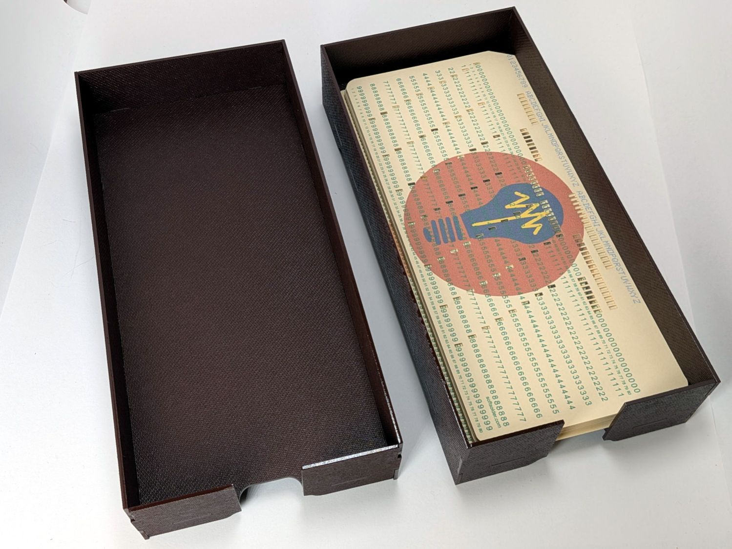
If you must have a stack of punched cards on your desk, a nice tray does wonders for the office decor:
Card Storage Tray – overview
That’s a coat of Rustoleum Painter’s Touch 2x [many more adjectives] Kona Brown Gloss rattlecan paint atop Trocraft Eco board. I sprayed the separate parts on a sheet of newspaper, waited 20 minutes, flipped them over, sprayed the other side, gave them another 20 minutes, and got them inside out of the wind for a day of curing.
They’re held together by cyanoacrylate adhesive dots between the tabs, with accelerator daubed on the other side of the joint to encourage prompt curing. In general I do not like cyanoacrylate, but sometimes it seems like the right hammer for the job.
The small squares near the corners of the image appear on every layer to properly register all the eagle outlines.
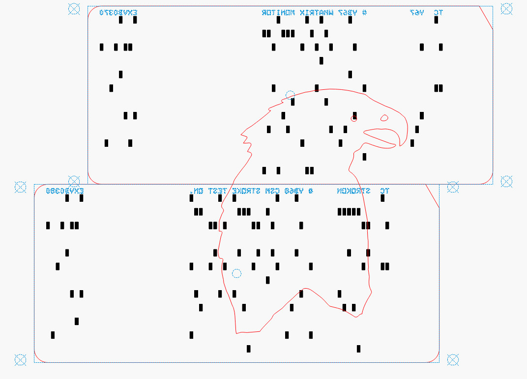
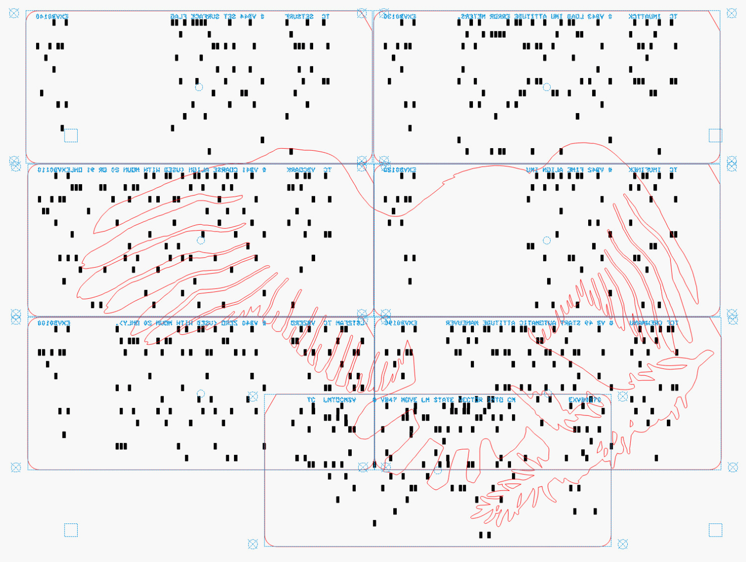
Mirroring the layout produces the hole pattern as seen from the back side of the cards, where the tape is applied:
Apollo Eagle – V4 Layer 7 card layout – mirrored
Then it’s (relatively) easy to align the cards while muttering “the rightmost hole in the lower sequence number is just about aligned with the upper card edge, which puts the middle-ish hole in the group of four in the 9 row over the left hole of those two” and so on and so forth. Cut off a strip of tape, carefully lay it along the joint between the cards, and add them to the outgoing pile.
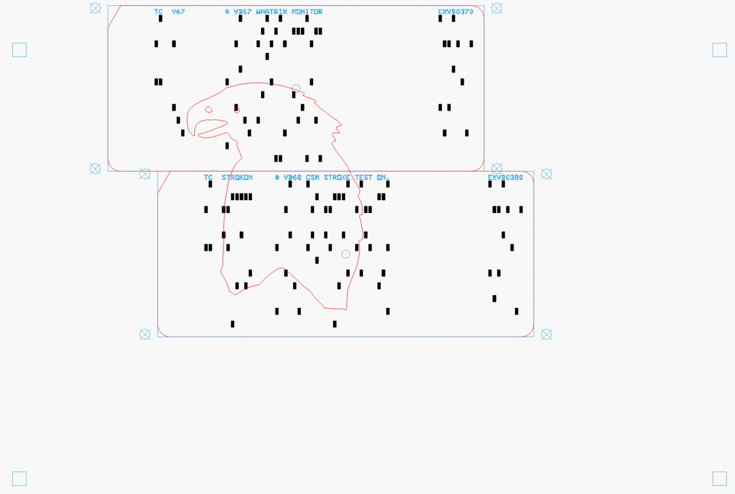
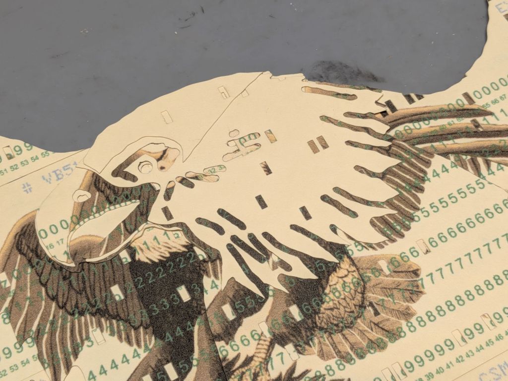
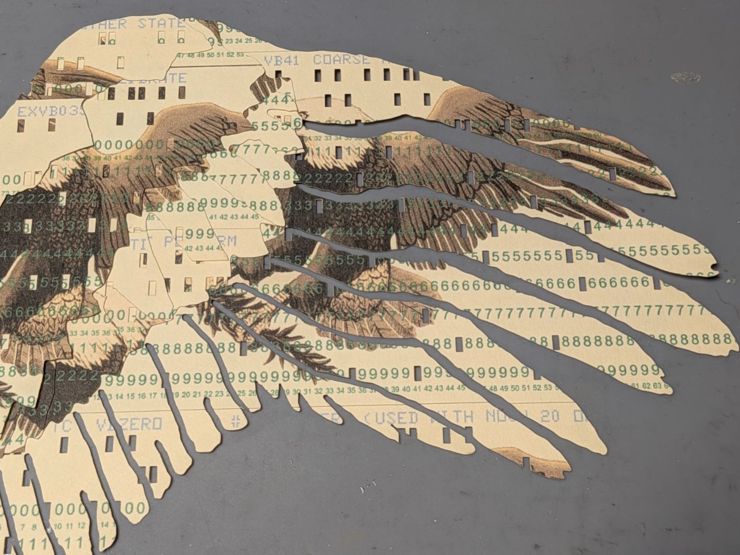
The top two layers are cut with the back = unprinted = blank side of the card upward to produce the eagle’s white head, with the outlines strategically located to avoid shredding the feathers with holes:
Apollo Eagle – V4 Layer 8-9 card layout
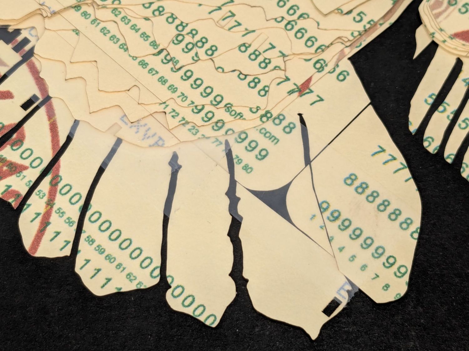
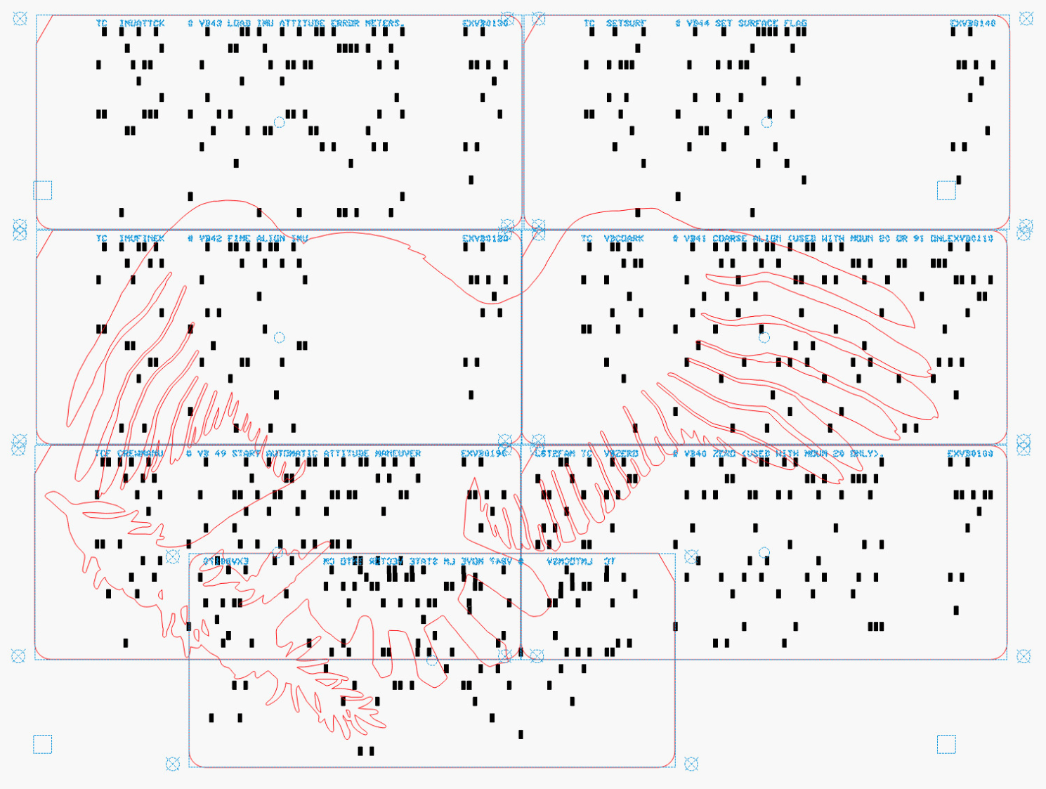
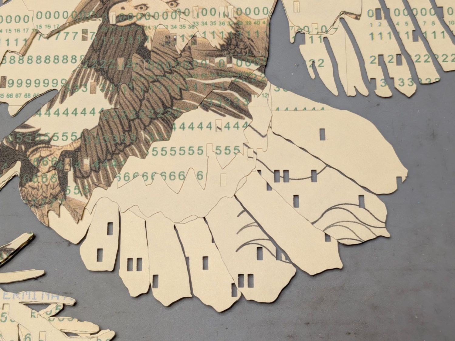
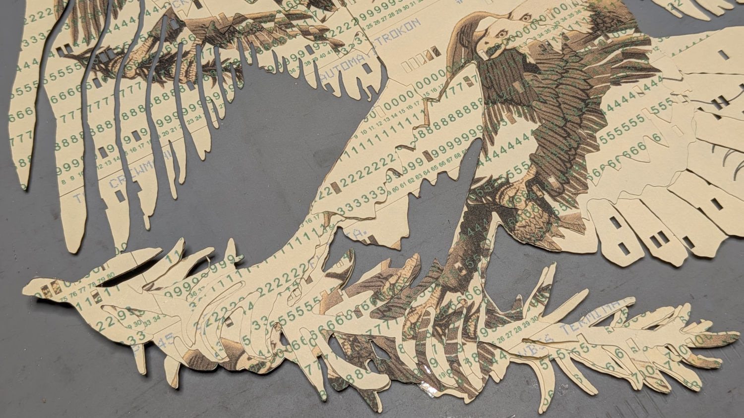
The value of this process becomes more apparent for the nine cards making up the bottom layer:
Apollo Eagle – V4 Layer 1 cards
Most of the white tail comes from the reversed card in the bottom row, inset into the two cards above it. The next layer covers those sections of the legs and olive branch, which is easy to confirm by aligning the layers using their border squares.
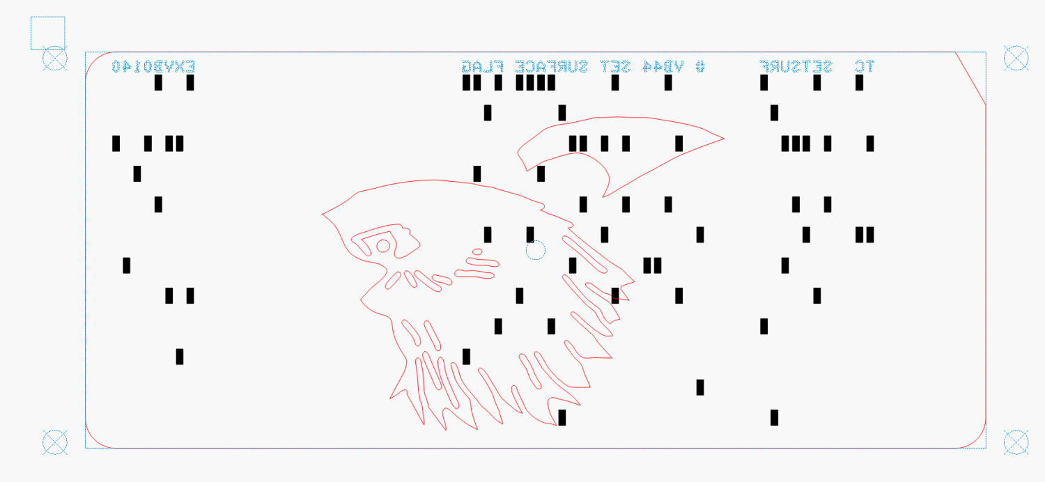
The layout mirrored for easier taping:
Apollo Eagle – V4 Layer 1 cards – mirrored
This is from a previous layout, but the improvement is obvious:
Apollo Eagle – V3 – tail
The trick with all this is to select only the eagle outline for cutting amid all the card details. Although putting the cards on a tool layer would avoid that problem, the holes are much less visible and they’re pretty much the entire point of this process.
Aligning the taped cards on the platform with the to-be-cut outline follows much the same process as aligning the printed cards for punching:
Select the cards and the eagle outline
Snap to the middle of the LightBurn workspace with the P key
Focus the laser on the cards if you haven’t already done so
Move the laser head to one of the card bevels using Ctrl-L and clicking on one end of the bevel
Skootch the cards to put that bevel at the red dot pointer location under the laser head
Move the laser head to another bevel
Skootch the cards as needed
Iterate until satisfied
Fire The Laser
Although each card layout has the four targets used to cut it from the printed card stock, those targets no longer exist on the cards because they’ve been cut off.
You could use Print and Cut to align the LightBurn workspace to the cards, but it’s easier and faster to just skootch the cards around.
Actually cutting the outline takes a few seconds and is kinda anticlimactic after all that setup.
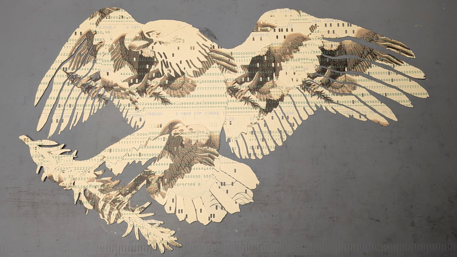
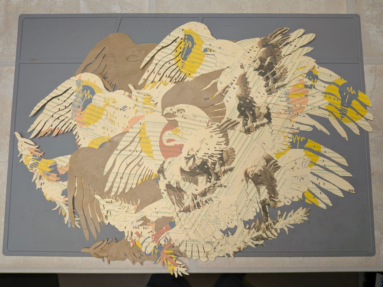
Stipulated: nobody ever ran punched cards through a multi-color printing process. A posterized version of the Apollo 11 mission patch eagle just seemed appropriate for cards containing a chunk of the mission source code.
Putting the tail feathers on two layers of reversed cards definitely improved the outcome:
Apollo Eagle – V3 – tail
The lines across two of the tail feathers come from inadvertently printing a quilting pattern intended for Letter paper after setting up a stack of 1/3 Letter blanks. Trust me on this: you do not discard any salvageable blooper cards.
The wing feathers get more definition and have sculptured upper layers:
Apollo Eagle – V3 – wing
The olive branch improved with fewer layers and contouring the claws makes them less chunky:
Apollo Eagle – V3 – olive branch
The beak and head now have slight contouring, with the neck feathers standing out nicely over the logo below:
Apollo Eagle – V3 – head
Although this is the third almost-ready version, it rests on the wings of many previous attempts:
Apollo Eagle – layered trials
The card joints on successive layers are now farther apart, although the long run across the middle of the body stands out more than I expected. The small pieces of cards at the top of the wings need more contrast.
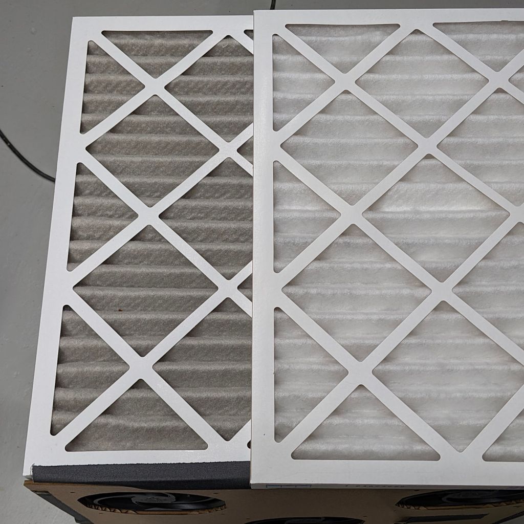
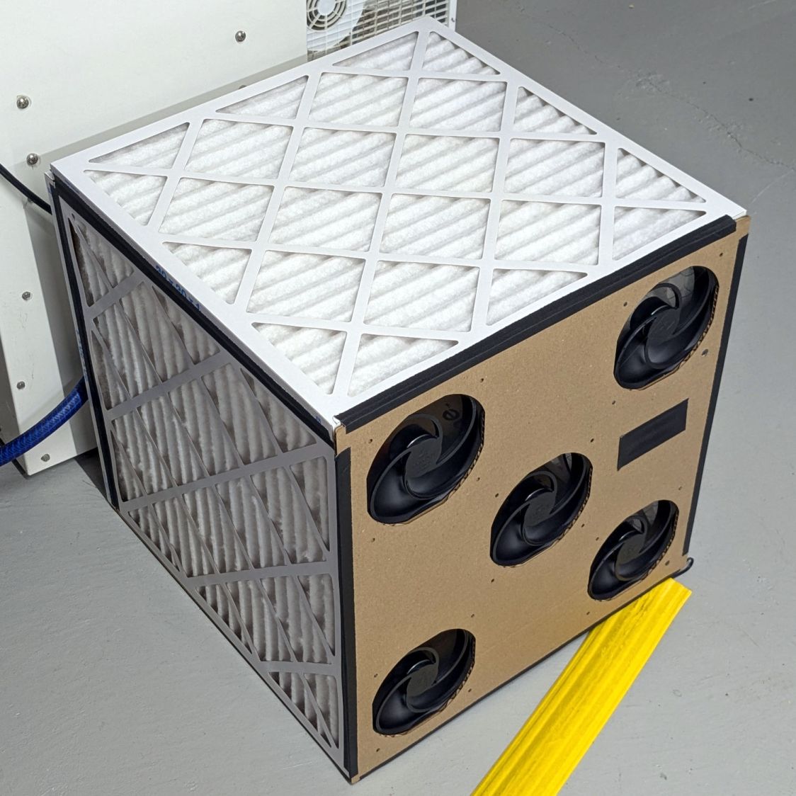
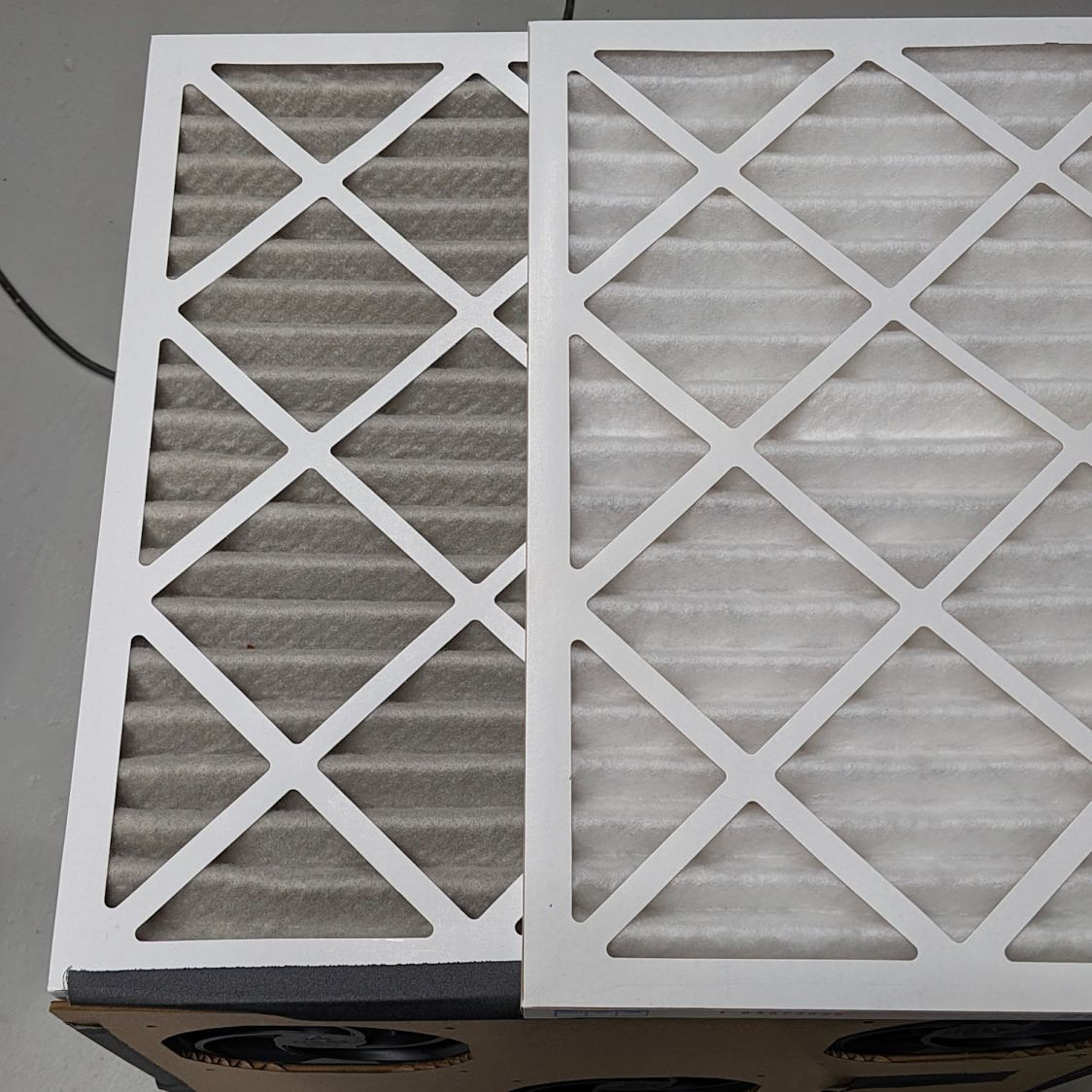
Running continuously for three months made the air filters look like this (with an unused filter on top for comparison):
Basement Air Filter Box – 3 months – A
I have not stretched the image contrast, so the new filter isn’t the pure white in the top picture, but it’s still about the same white as the cardboard frame. The floor is, indeed, painted gray.
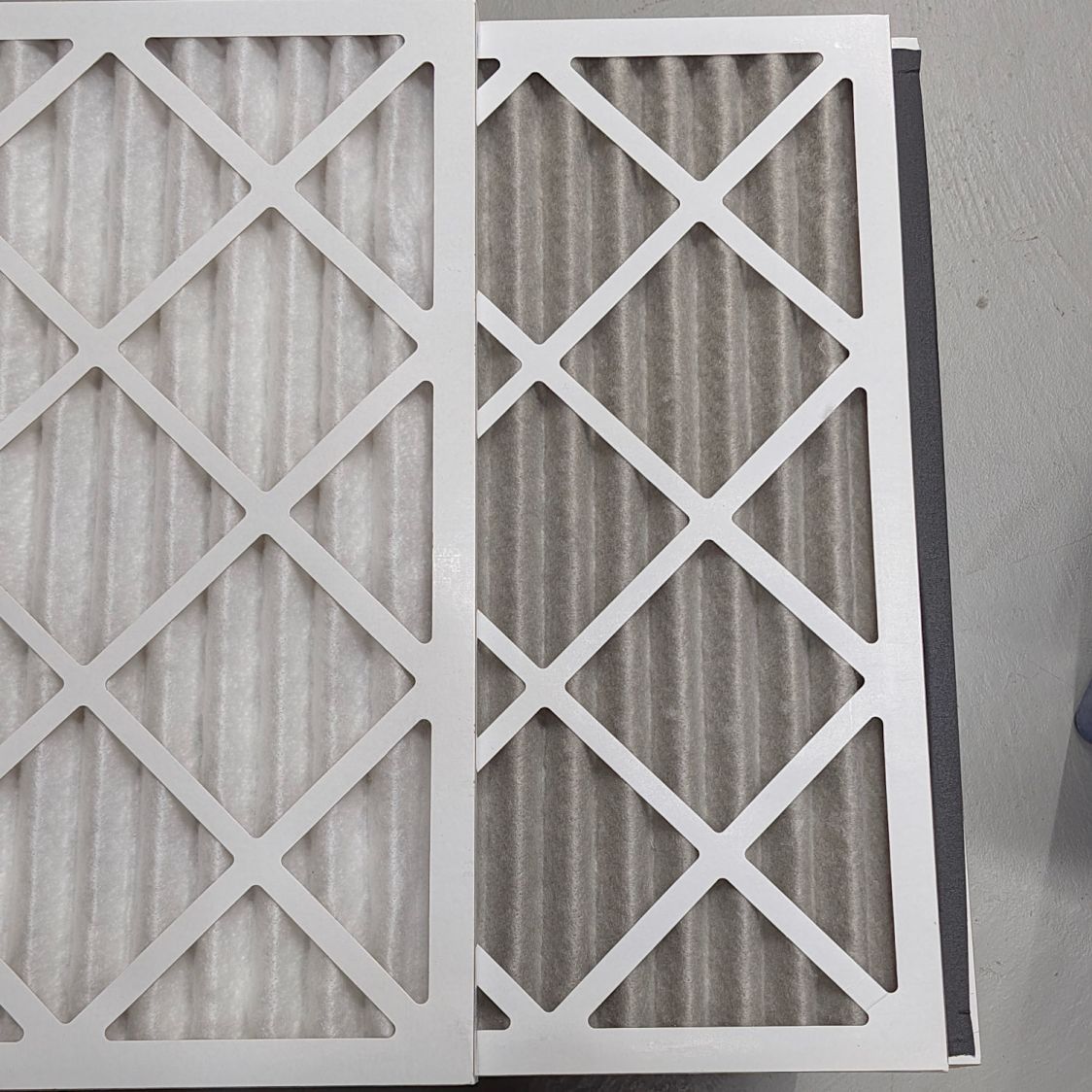
Looking at the pleats in the other direction to show I’m not making it up:
Basement Air Filter Box – 3 months – B
The inside surface of the filters has the same gray appearance. The fans are, unsurprisingly, immaculate.
Totally did not expect that!
The filters sport a MERV 13 rating and snag “most smoke” from the passing air, so they’ve been collecting any fumes not sucked out of the laser cutter, along with whatever arises from other Basement Shop™ activities.
So I’ll buy another set of filters, build another box, and see what accumulates during the next three months.
As long as the voltage limit is over about 10 V, it will (likely) never matter, as the LED forward drop doesn’t vary much with temperature. Setting it to something sensible keeps it out of the way.
The middle trimpot apparently sets a voltage for a comparator to light an LED when the battery current drops below that level as it reaches full charge.
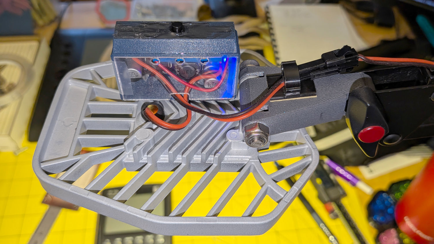
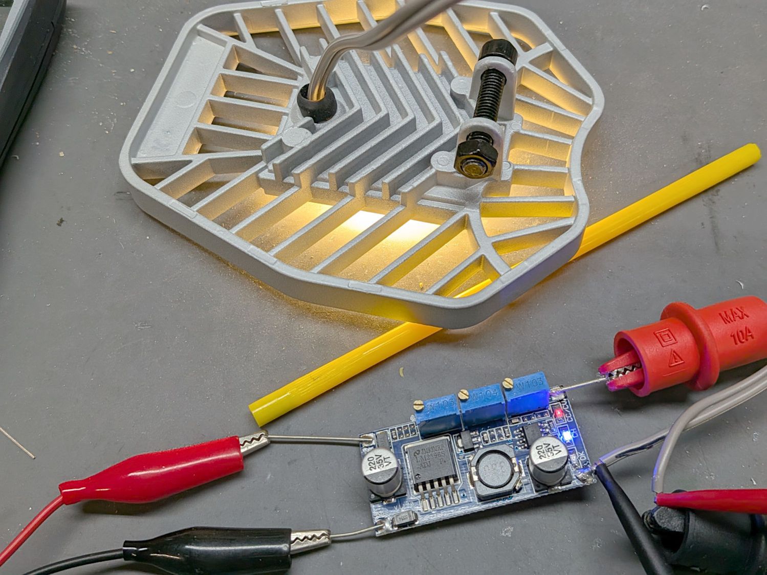
Although the regulator touts its high efficiency, it does run hot and a heatsink seemed in order:
LED Garage Light – heatsink
Stipulated: the fins run the wrong way and it’s sitting in the updraft from the main heatsink. It’s Good Enough™.
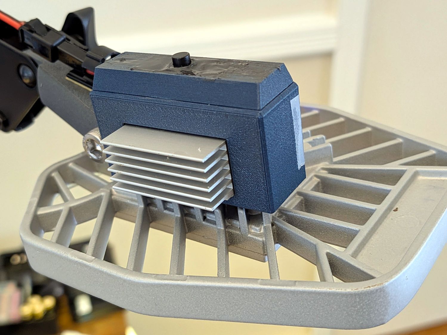
The switch on the top comes from the collection of flashlight tailcap switches and controls the 12 V input power. It’s buried up to its button in a generous dollop of JB Kwik epoxy, which seemed the least awful way to get that done.
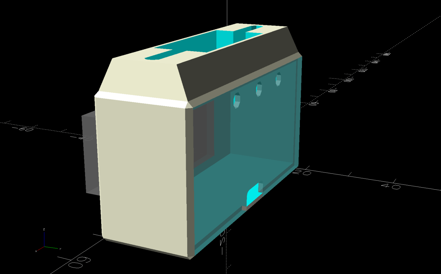
The solid model looks about like you’d expect:
LED Lamp Driver case – switch housing – show solid model
The OpenSCAD code exports the (transparent) lid as an SVG so I can import it into LightBurn and laser-cut some thin acrylic. Two tape snippets hold the lid in place pending more power-on hours, after which I’ll apply a few dots of cyanoacrylate adhesive and call it done.
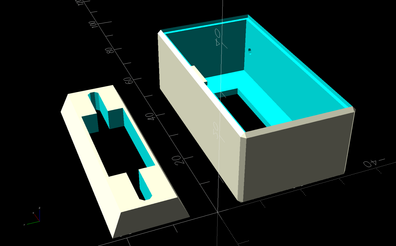
The case builds in two pieces that glue together to avoid absurd support structures:
LED Lamp Driver case – switch housing – build solid model
A 3D printed adapter goes between the desk lamp arm and the lamp heatsink bolt:
LED Lamp Driver case – arm adapter – solid model
The OpenSCAD source code files for the case and adapter arm as a GitHub Gist:
This file contains hidden or bidirectional Unicode text that may be interpreted or compiled differently than what appears below. To review, open the file in an editor that reveals hidden Unicode characters.
Learn more about bidirectional Unicode characters
This file contains hidden or bidirectional Unicode text that may be interpreted or compiled differently than what appears below. To review, open the file in an editor that reveals hidden Unicode characters.
Learn more about bidirectional Unicode characters
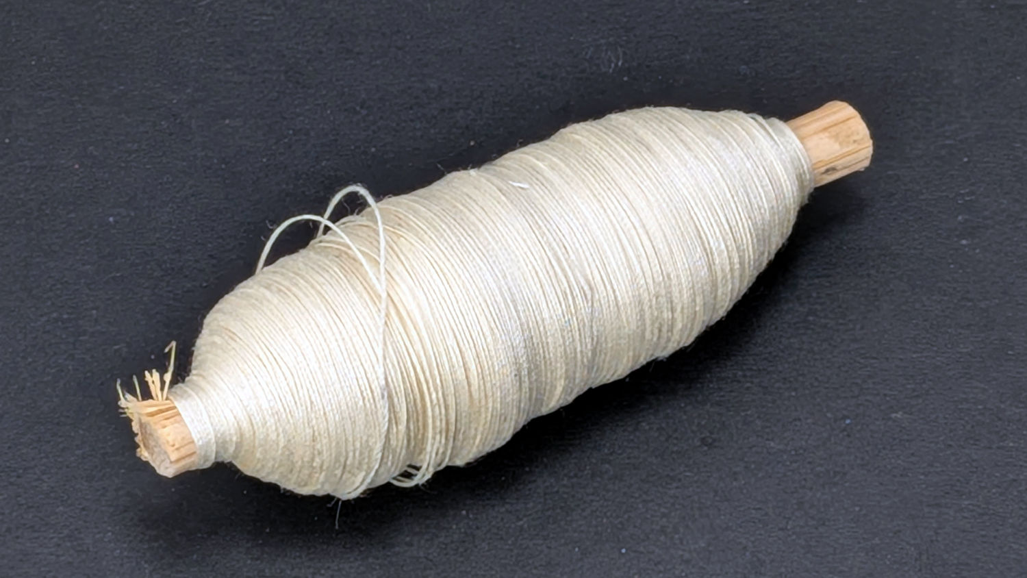
The Industrial Age bobbin winder for Mary’s HQ Sixteen long-arm machine bunched the thread on one end of the bobbin, rather than distributing it in even layers as it should. Tinkering with the thread tension setting being unavailing, I settled in for some debugging.
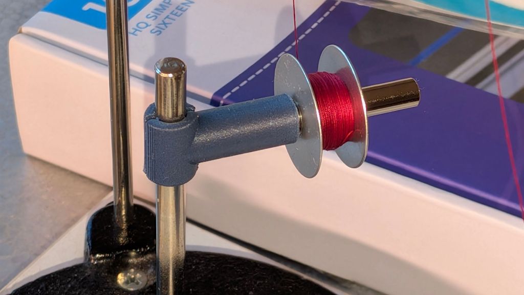
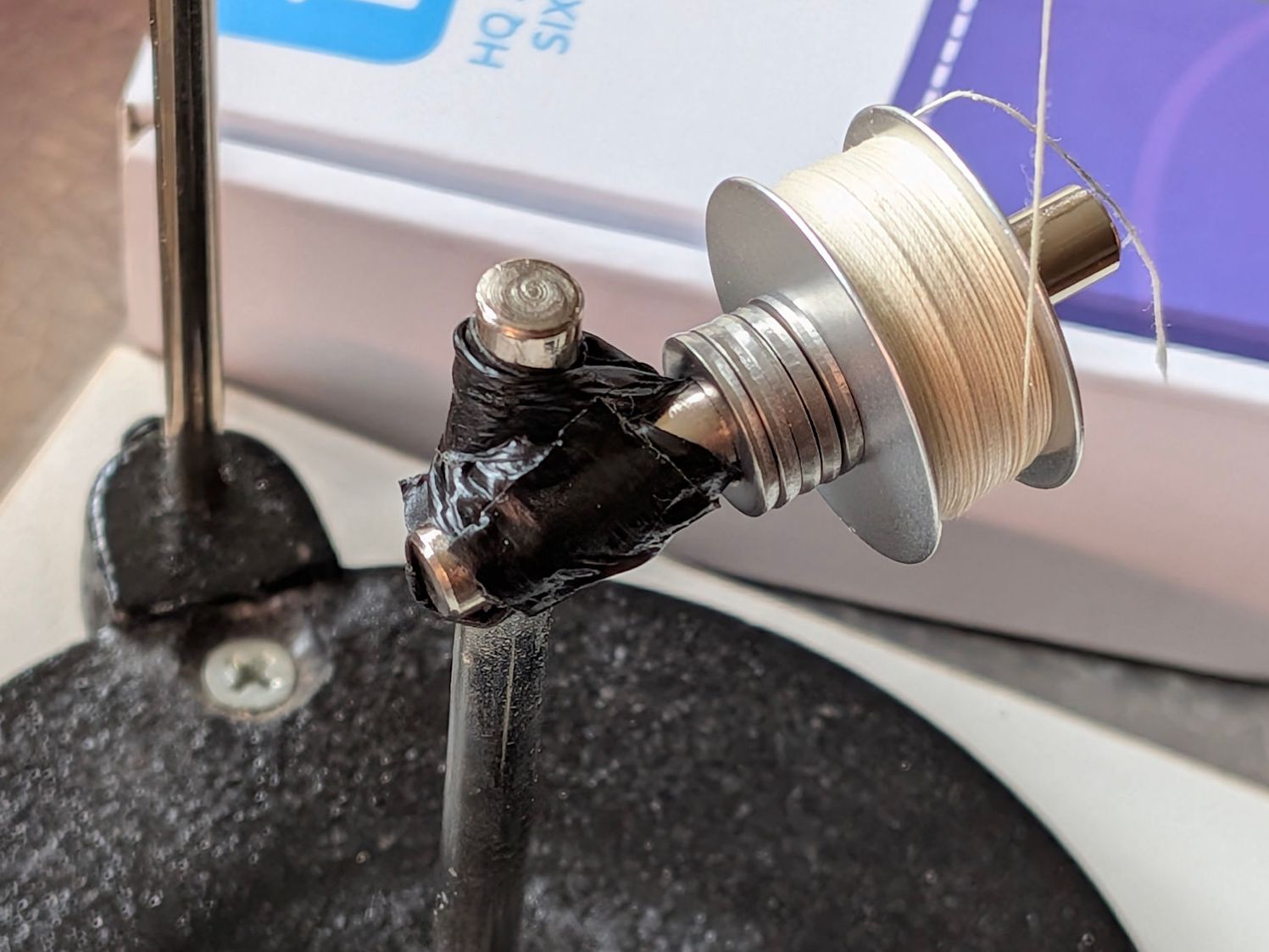
After filling two bobbins from a spool of the thread Mary uses for practice quilts, I decided I should reuse the thread. Mounting the filled bobbin on a 6 mm horizontal shaft attached to the vertical pin normally locating the spool let the thread pay out in the proper orientation, with a duct-tape lashup holding the shaft in place:
HQ Sixteen bobbin unwind adapter – expedient version
I added the stack of washers to keep the bobbin away from the duct tape after having the tape’s adhesive migrate onto the spinning bobbin.
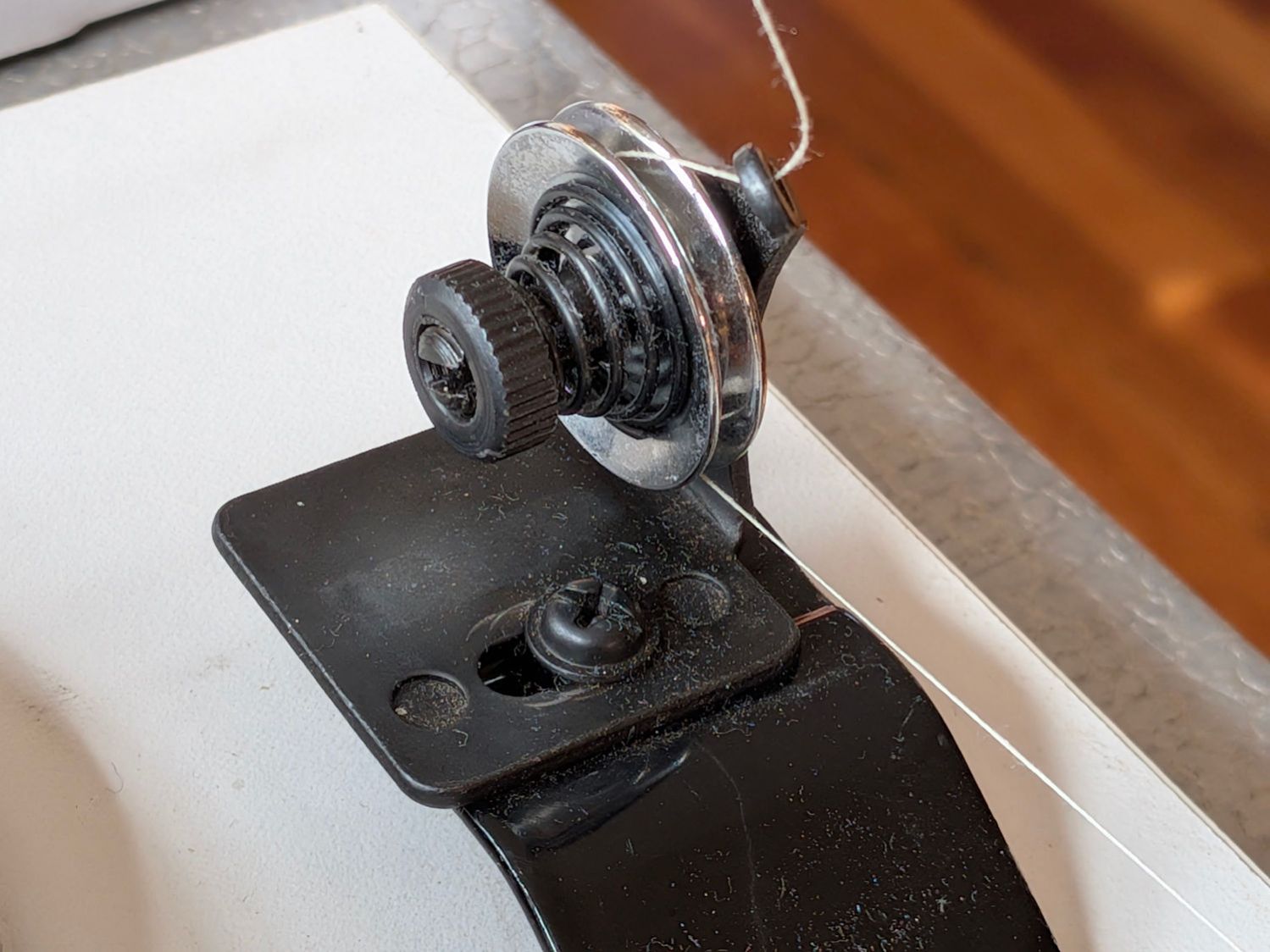
The thread from the spool or, in my case, a filled bobbin, passes between a pair of tension disks on its way to the bobbin spun by the motor:
HQ Sixteen bobbin winder – thread path
A conical spring presses the tension disks together, with the thread clamped between them:
HQ Sixteen bobbin winder – tension disk overview
The instructions suggest using “the lightest tension possible”, but backing the nut off to hang by its fingernails had no effect. The spring has a bent end passing through the slotted shaft, so rotation of the disks won’t unscrew the nut.
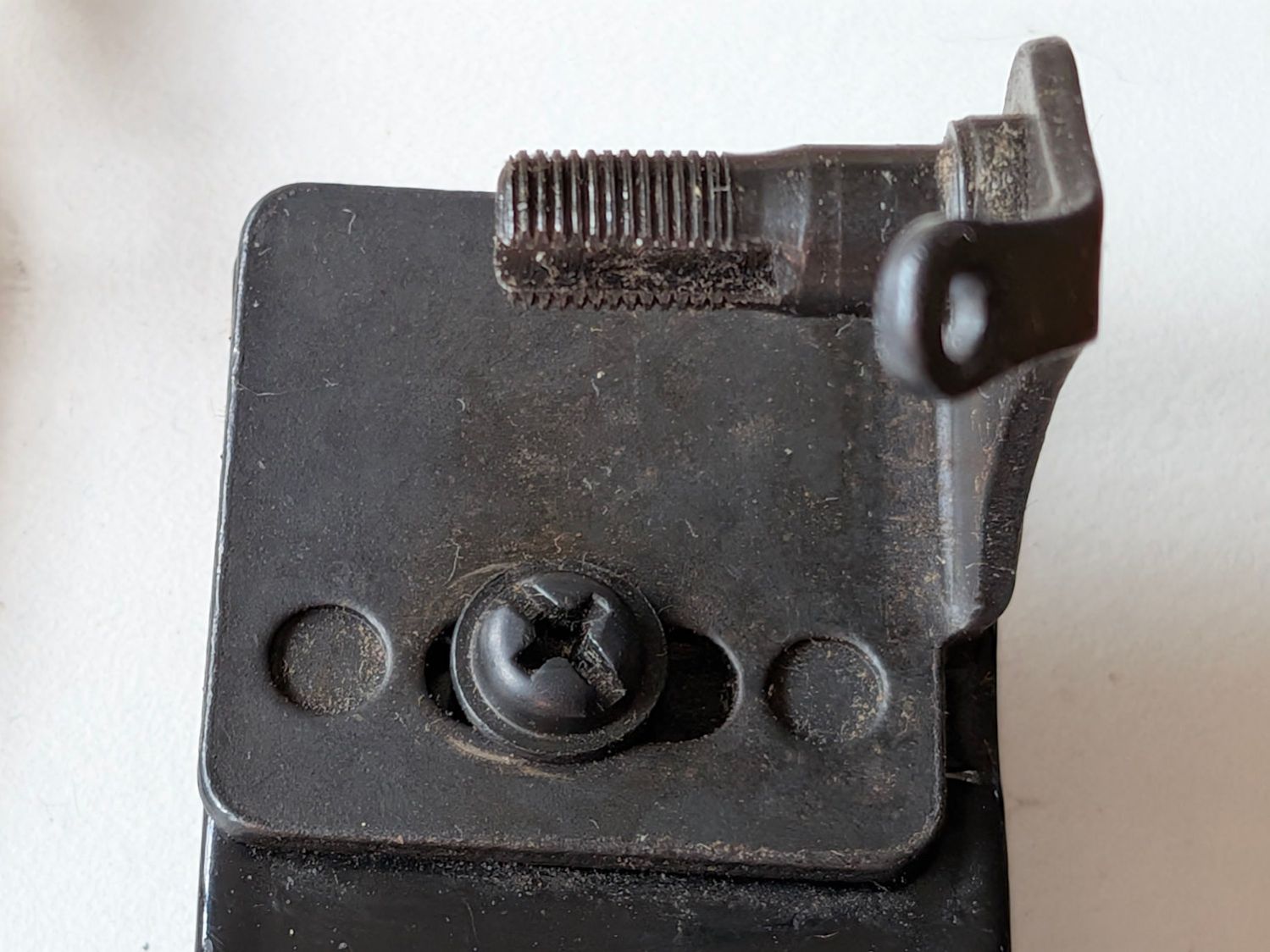
The washer under the mounting screw left slight scars in the black oxide finish on the fixture, presumably from previous attempts to adjust the thing:
HQ Sixteen bobbin winder – tension disk base
The threaded shaft is not exactly parallel to the base, because the upright arm is slightly over-bent, but I think that has no effect on the outcome, because the thread path doesn’t depend on the disk angle.
Because the thread accumulated on the outer side of the bobbin (to the right in that picture), I loosened the mounting screw and shoved the fixture all the way to the left. That should, if anything, bias the thread accumulation to the other (inner) side of the bobbin.
As it turned out, relocating the tension disks caused the thread to distribute evenly across the bobbin, with only occasional hesitations and no significant accumulations; Mary pronounced the result entirely satisfactory.
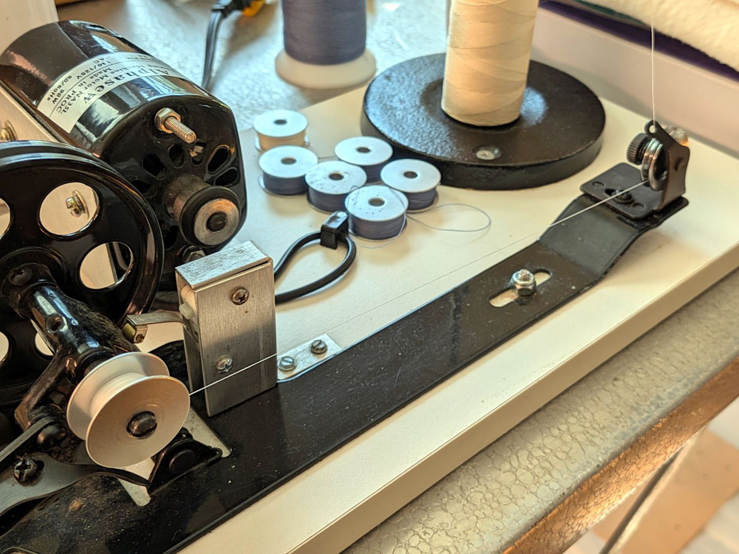
The motor dataplate says it runs at 7000 RPM, so the 3/4 inch O-ring drives the 4 inch wheel at about 1300 RPM. This was sufficiently terrifying I immediately set up a triac speed control (intended for a router) to throttle it down, but with the bobbins now filling properly we run the motor at full speed and it fills a bobbin in 23 seconds flat.
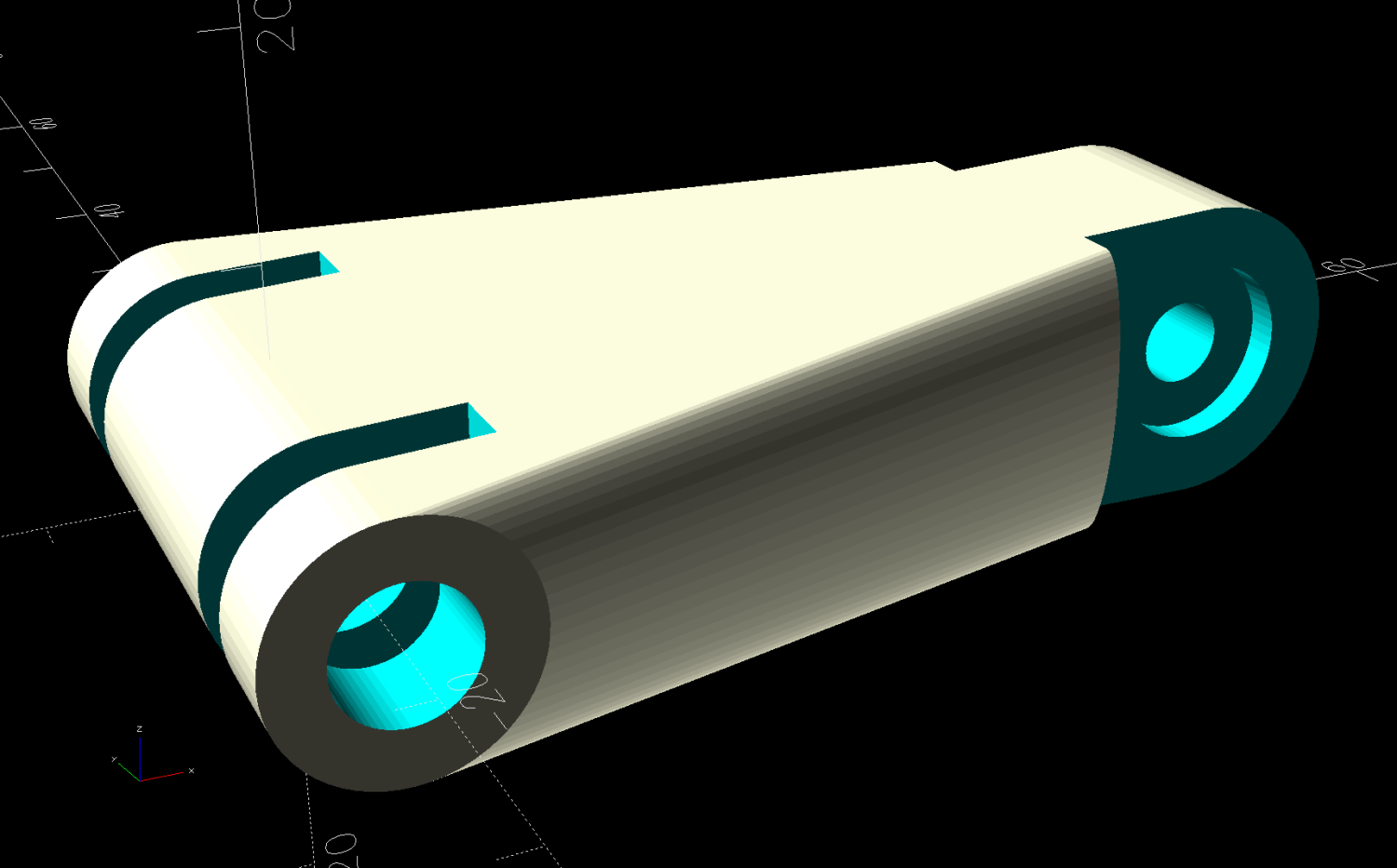
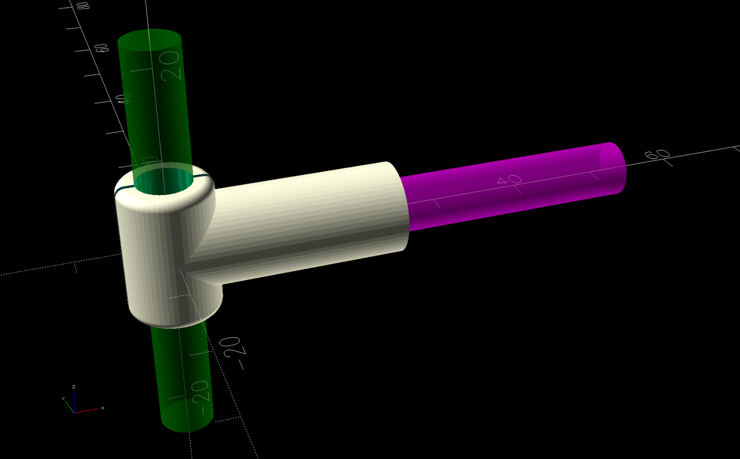
After we filled half a dozen bobbins with blue thread for the quilt project, I conjured an adapter from the vasty digital deep for a snippet of 6 mm rod with a D-shaped end:
Bobbin Unwind Adapter – solid model – show
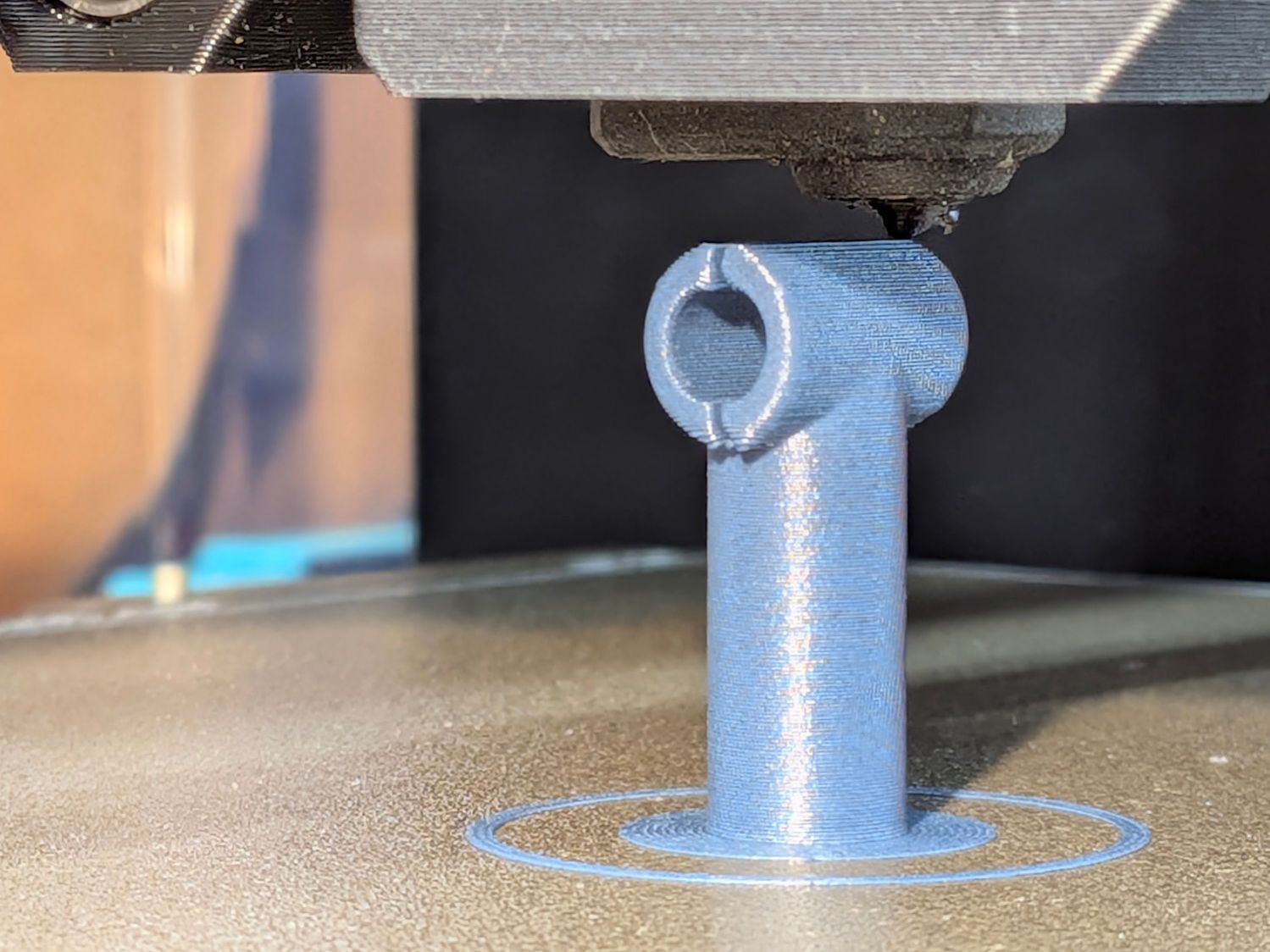
The adapter builds on one leg, with a brim for stability:
HQ Sixteen bobbin unwind adapter – on platform
And looks like it belongs there:
HQ Sixteen bobbin unwind adapter – installed
It’s now in the box of HQ Sixteen bobbins, where we both hope it will remain undisturbed forevermore.
Although the vertical pin locating the spools (and holding the adapter) is nominally 6 mm, burrs in the chrome plating prevented the bobbin’s 6 mm bore from sliding over it. In retrospect, that prevented me from just dropping the bobbin on the pin and unwinding the thread over the side of the bobbin, which likely avoided some serious-to-lethal thread tangles.
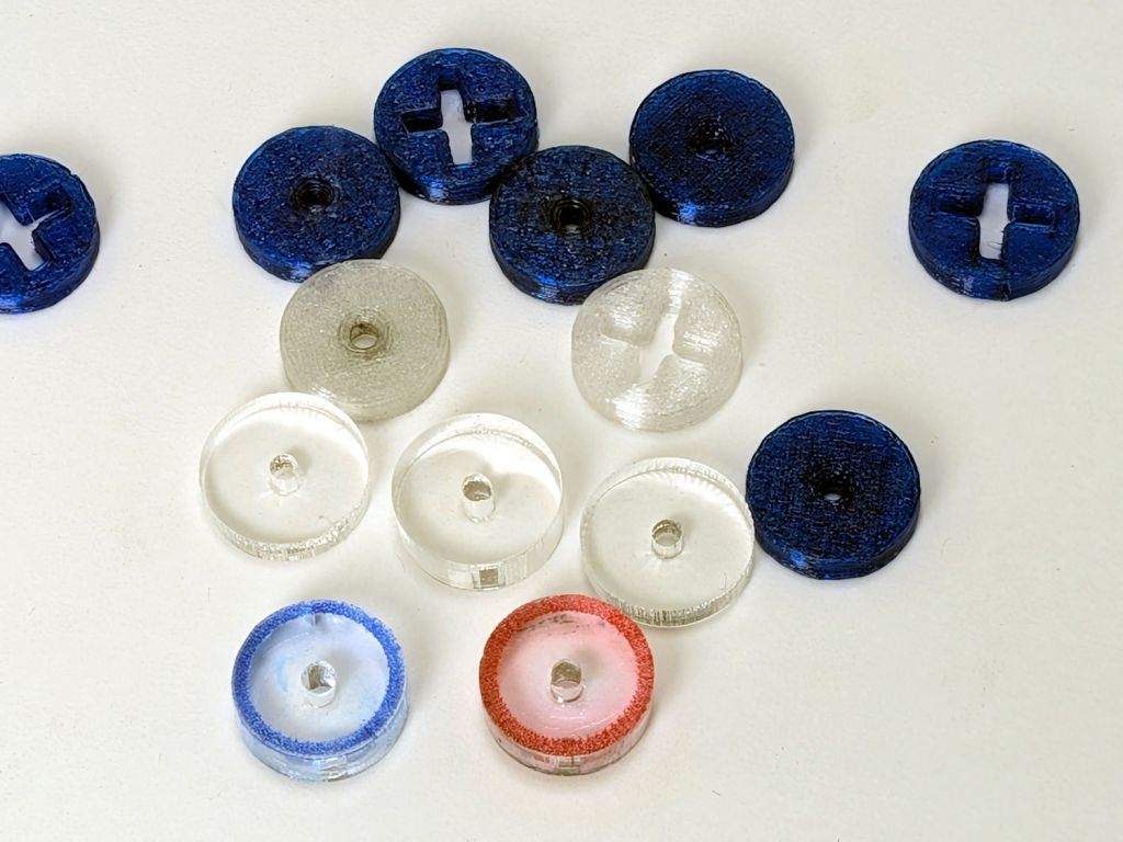
After all that debugging, I had several bobbins full of well-worn thread, so:
This file contains hidden or bidirectional Unicode text that may be interpreted or compiled differently than what appears below. To review, open the file in an editor that reveals hidden Unicode characters.
Learn more about bidirectional Unicode characters
So the engraved ring on the two in the front row carries a cheerful Sharpie color to make them stand out. I wanted to use fluorescent acrylic, but I don’t have any 4 mm sheets and stacking a pair of 3 mm sheets → 6 mm will be too thick for the pencil tip.
What looks like dirt on the red guide comes from internal reflections or the lack thereof: it’s perfectly transparent in person, honest.