Ed Nisley's Blog: Shop notes, electronics, firmware, machinery, 3D printing, laser cuttery, and curiosities. Contents: 100% human thinking, 0% AI slop.
Tag: Improvements
Making the world a better place, one piece at a time
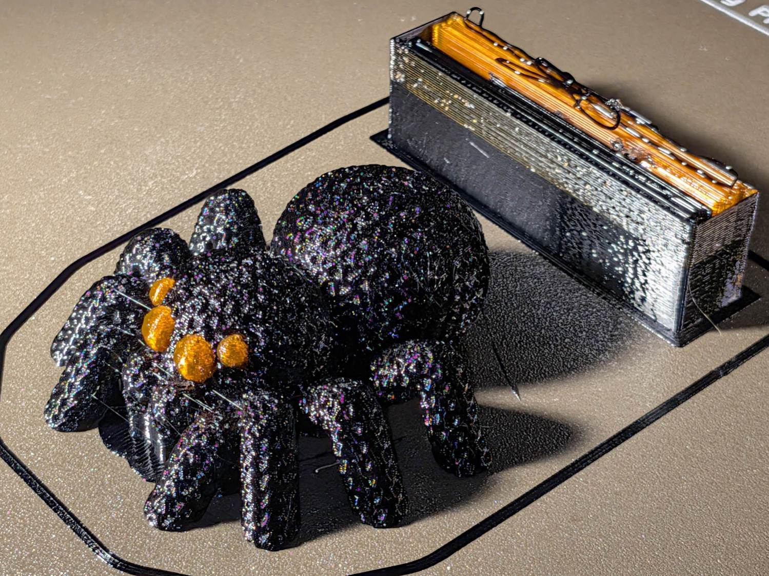
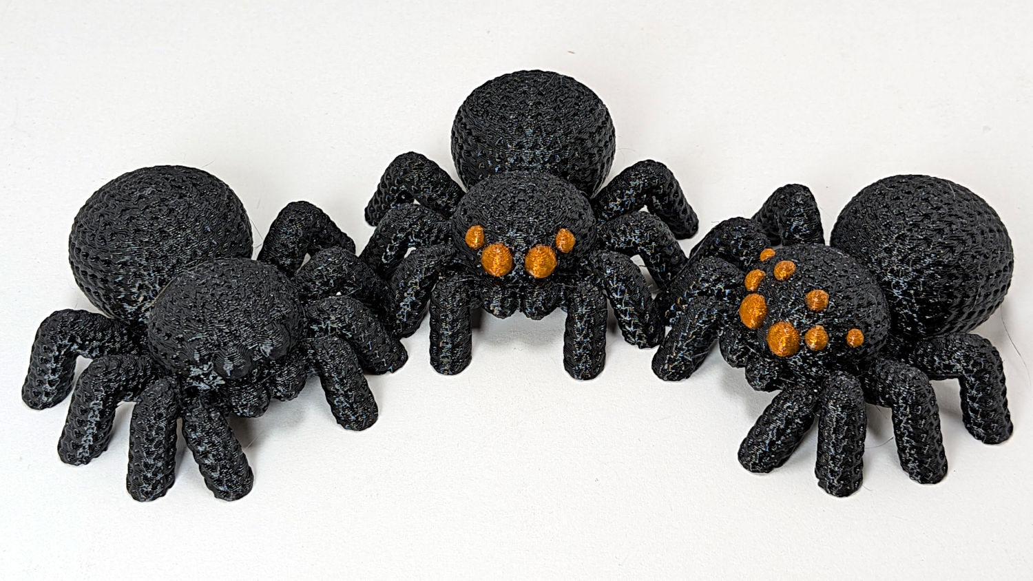
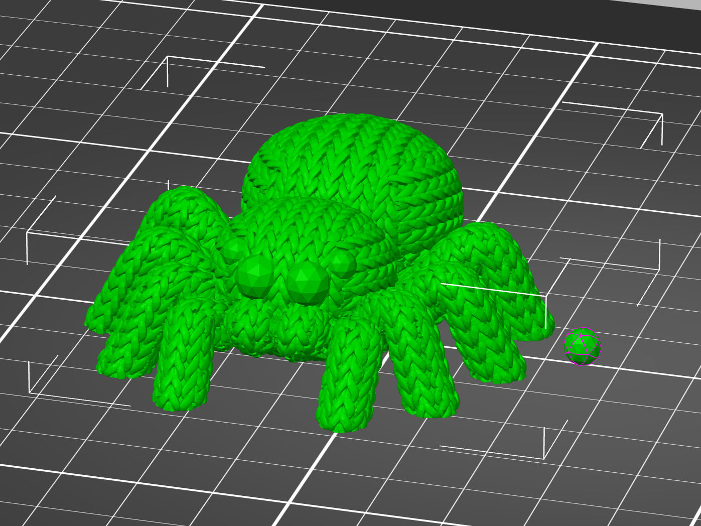
But all-black looked rather somber, even for an All Hallow’s Eve decoration, so I used PrusaSlicer’s Multi-Material Painting to print the eyes in retina-burn orange:
Knitted Spider – orange eyes – wipe tower
The chunky wipe tower shows the cost of switching filaments for a quartet of little eyes. The new Prusa INDX extruder design reduces that waste, but I’m not going there.
You can see the block of painted-on support under the palps, which worked better than overenthusiastic automatic support generation.
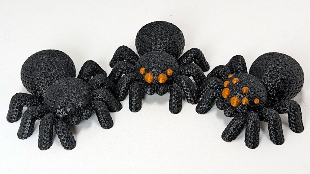
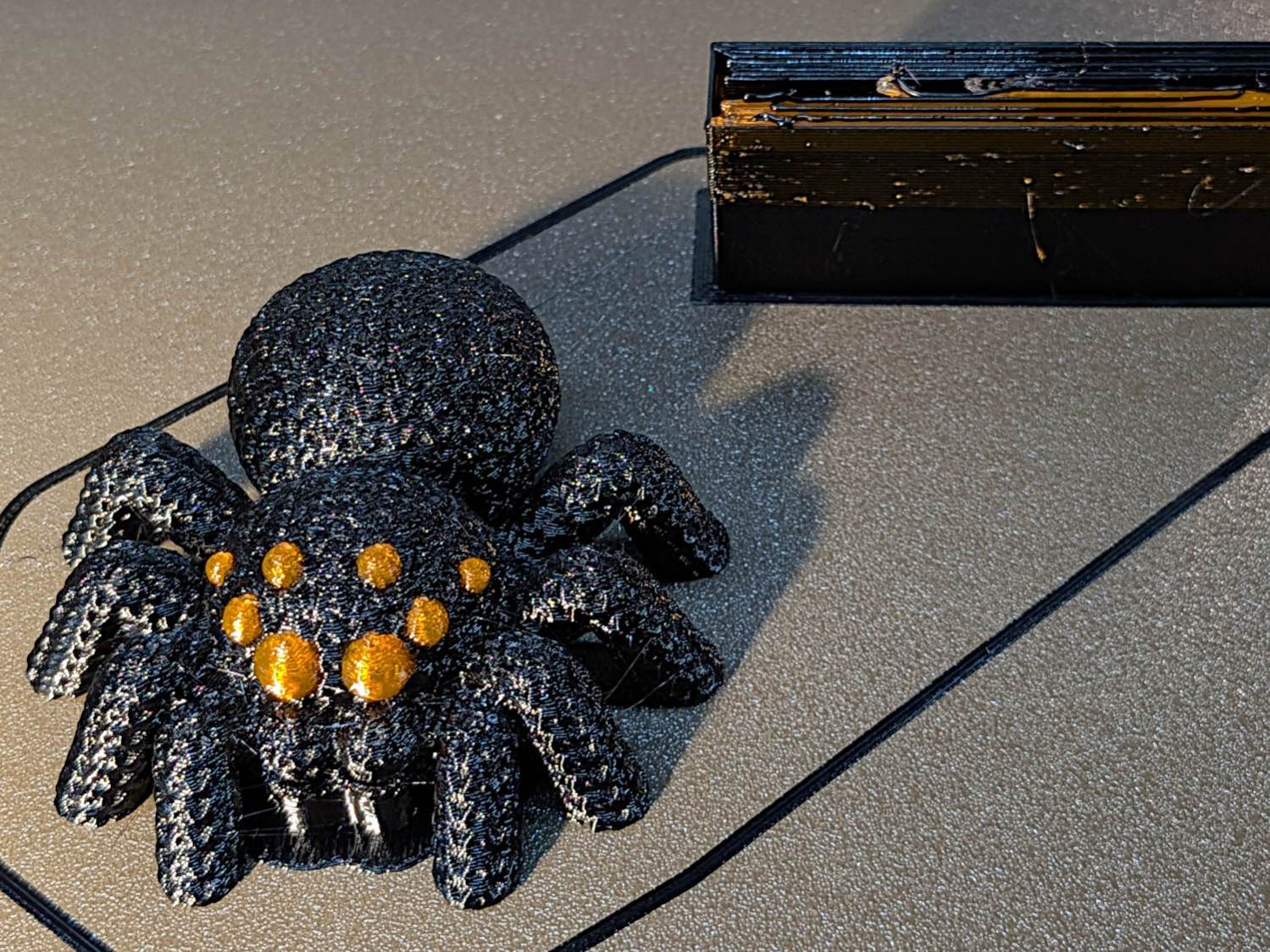
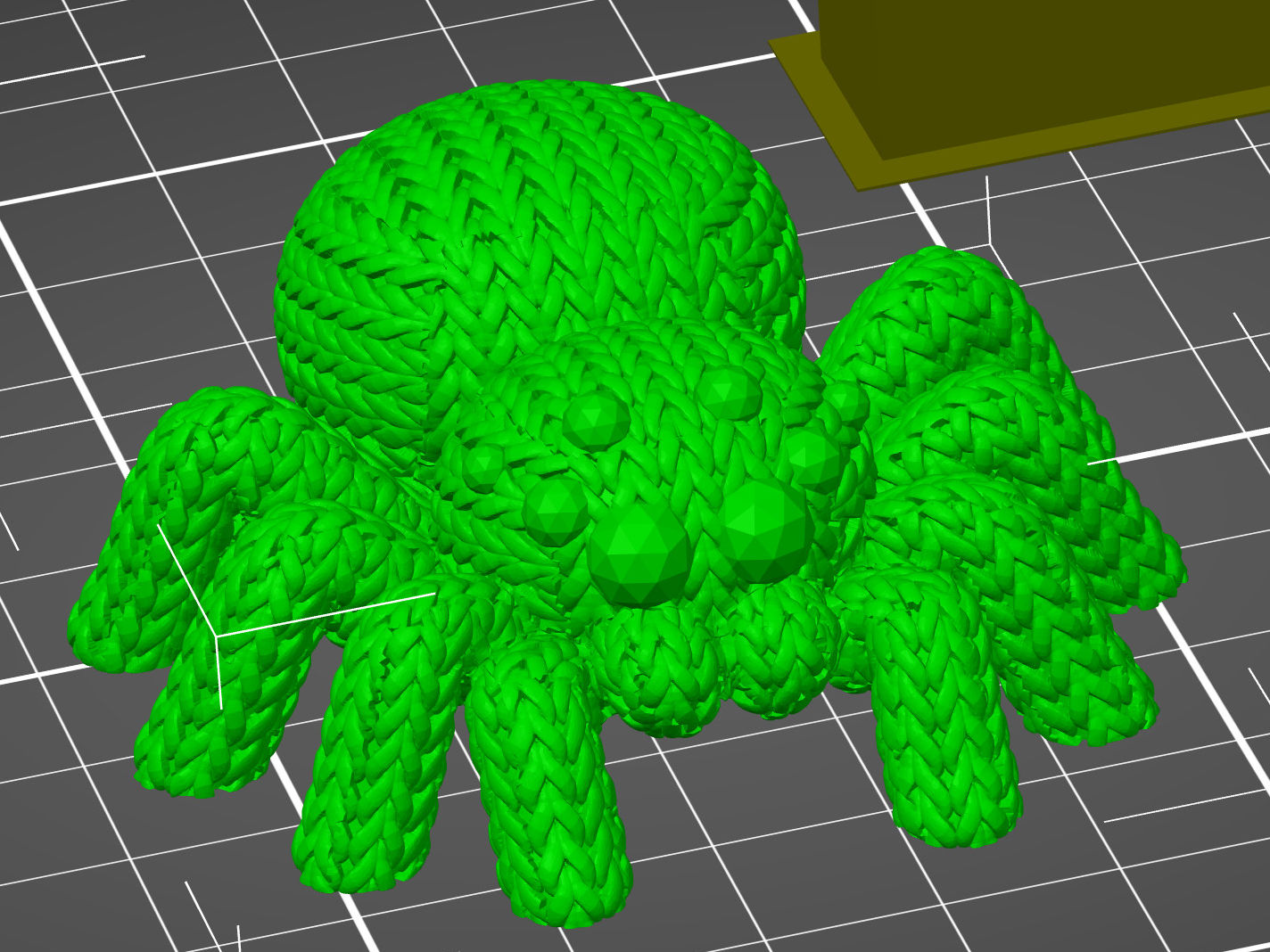
The consensus suggested the spider suffered from insufficient eye, so I upleveled it to maximum spider spec:
Knitted Spider – 8 eyes – on platform
Which looks like evolution in action:
Knitted Spider – iteration
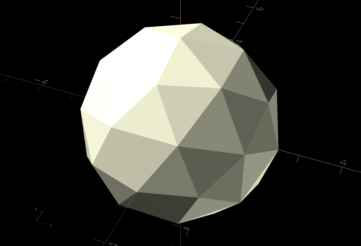
The additional eyes came from a trivial OpenSCAD / BOSL2 sphere:
include <BOSL2/std.scad>
spheroid(d=5.0,style="icosa");
Which is both small and large enough to have a useful number of facets:
Knitted Spider – 5mm icosa sphere eye model
Those facets will come in handy for Multi-Material Painting.
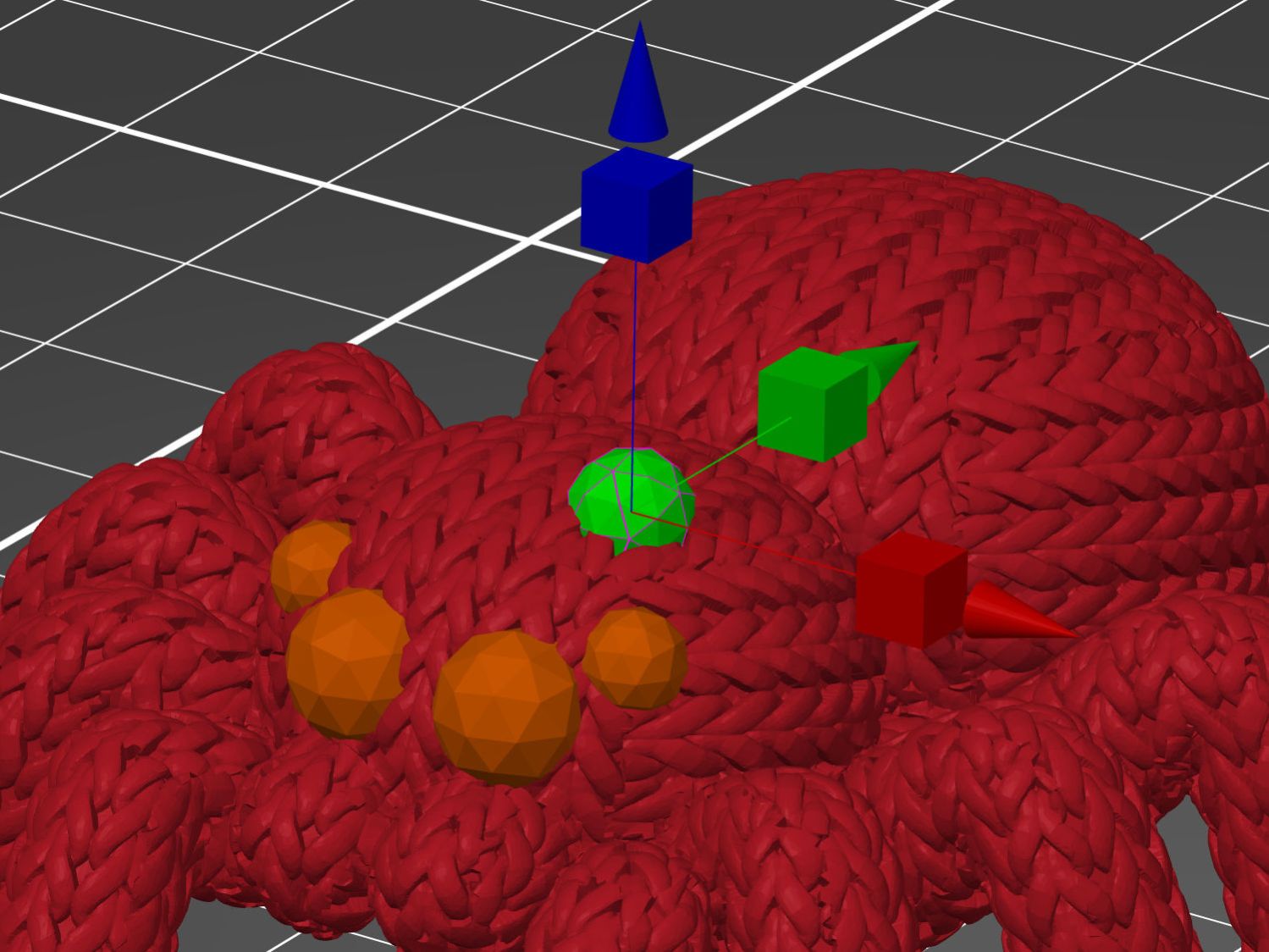
Then you can use the Move tool to haul the sphere into place:
Knitted Spider – eye positioning
Use the Scale tool to reduce it to a suitable size.
With the eye in place, copy-n-paste creates a duplicate Merged sphere at the same coordinates, which you chivvy into its proper spot. Repeat as needed for more eyes!
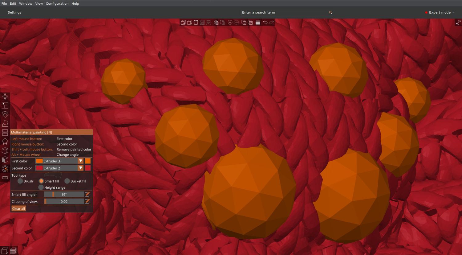
The sphere facets are far below the 0.4 mm nozzle’s resolution, but they simplify painting the eye with “Smart Fill” angle settings:
Knitted Spider – 8 eyes – slicer material painting
I had initially thought to just drop separate spheres in place and assign them to the orange extruder, but the slicer (quite properly) treats them as separate objects and creates balls sitting in sockets.
Instead, the eyes must become part of the spider’s shape, have their exterior surfaces painted, then get sliced. In order to do that, I exported the 8-eyed spider as a new STL file and imported it back for painting & slicing:
Knitted Spider – 8 eyes – slicer model
The original single-color spider prints in an hour and adding any number of eyes doubles the time, so those MMU3 tool changes are expensive. Although the printer is reliable, the auto-retract spools I set up sometimes retract the filament beyond the feed gear inside the MMU3, which the firmware detects and calls for manual intervention. It’s best to be puttering in the basement while the printer buzzes away.
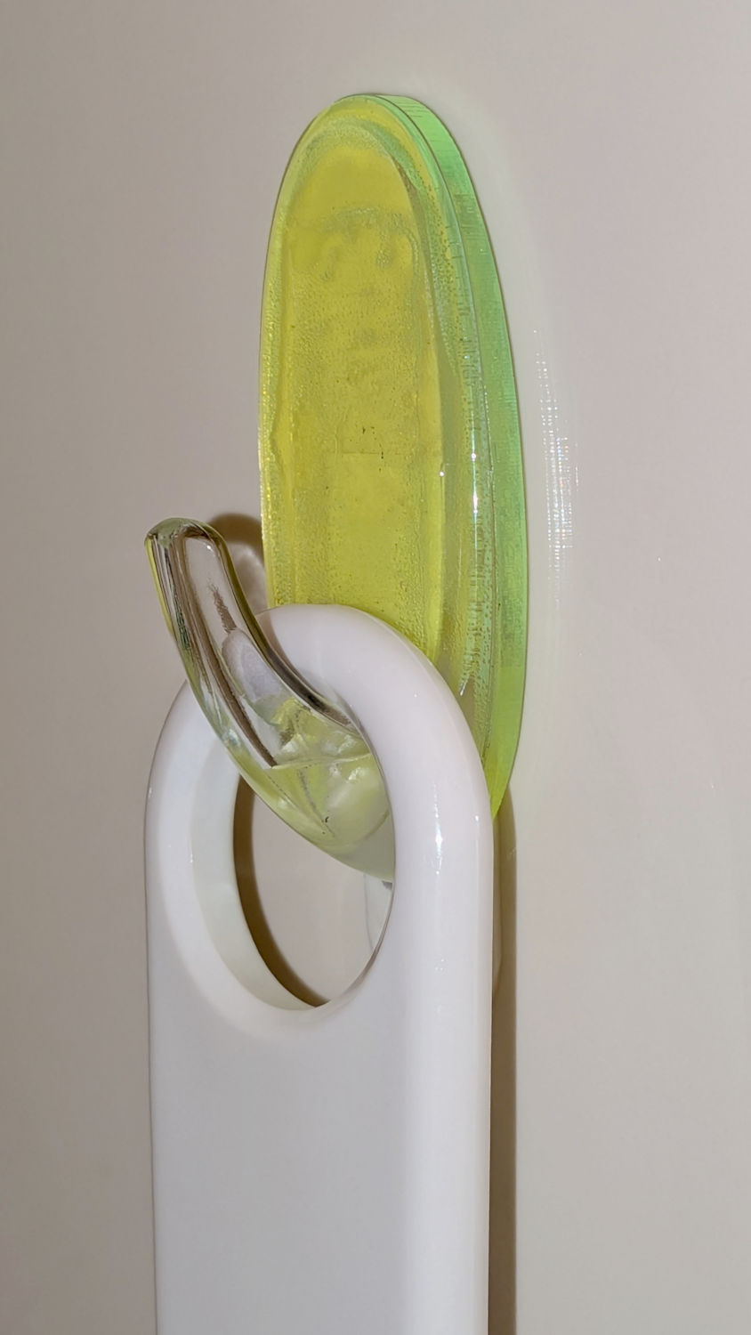
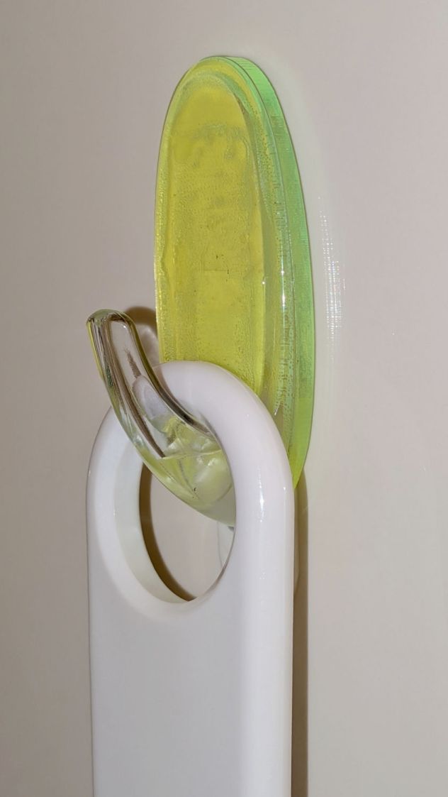
Perhaps a 3 mm spacer behind the Command Hook holding the shower squeegee to the stall will let the blade dry out between uses:
Shower Squeegee Hanger – installed
It’s fluorescent green acrylic, because why not?
As with all such things, start with a scan of the base:
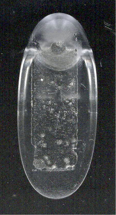
Command Hook – base scan
Then:
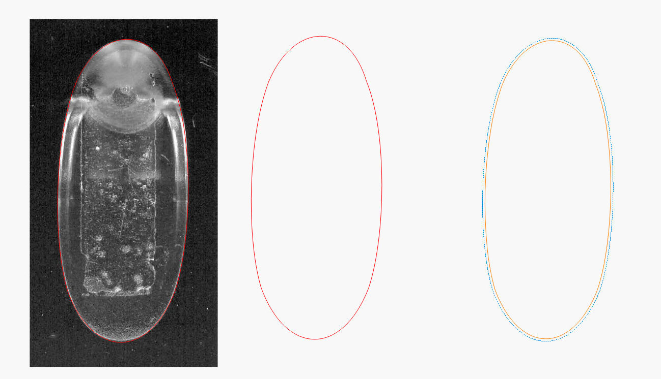
Import into LightBurn
Draw a rectangle fitting the base
Convert to a path
Node Edit to put the corner nodes on the perimeter
Tweak node handles to match curves to perimeter
Fire The Laser
Contrary to what I expected, the base is not symmetric.
The layout includes another, slightly inset, path to cut a matching shape of 3M 300LSE adhesive to stick the Command Hook onto the acrylic:
Shower Squeegee Hanger – spacer plate
You could stick a rectangle of 300LSE to the acrylic and cut both in one operation, but making the sheet slightly smaller prevents sticky edges, at the cost of aligning the cut sheet on the fly.
The Command Hook’s base is not flat, even after mostly removing the remainder of the previous Hook adhesive, so the 300LSE didn’t bond across the whole thing. If water weakens the bond and it falls off the wall (surely in the middle of the night), the next time around I’ll sand the base flat.
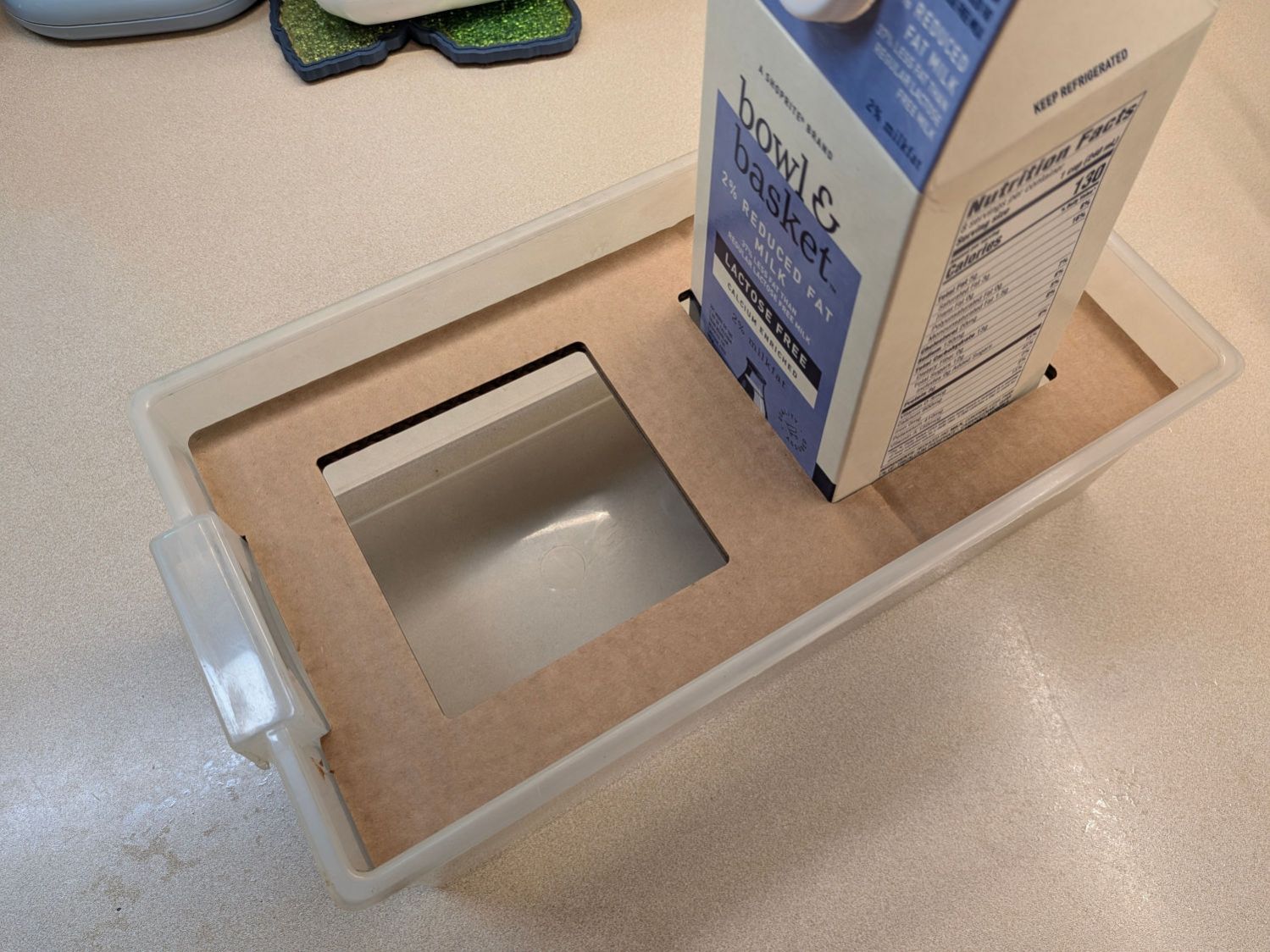
Mary wanted to haul seedlings started in half-gallon milk bottles to their destination and I figured they shouldn’t slide around while being transported:
Milk bottle seedling starter carrier
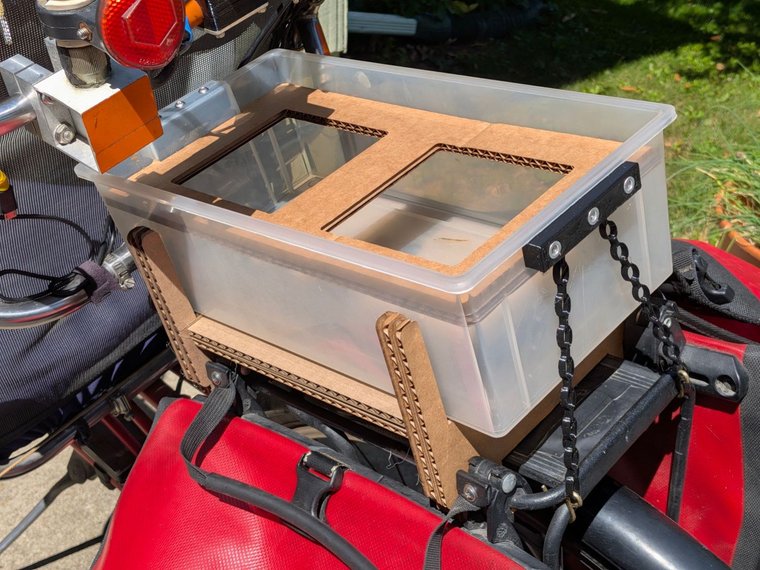
That’s a half-width drawer from the same salvaged collection that produced the Bike Rack Tray Holder and a few minutes with LightBurn adapted the wider cardboard bike rack mount to fit the narrower drawer:
Bike Rack Tray Holder – small – LightBurn layout
Basically, use Node Edit to delete the horizontal lines, move the sides inward by half the difference of the drawer widths, then draw a few short lines to close the gaps.
Hot-melt gluing four layers of cardboard with crossed corrugations, plus three flat bottom layers, got it done:
Bike Rack Tray Holder – small drawer – installed
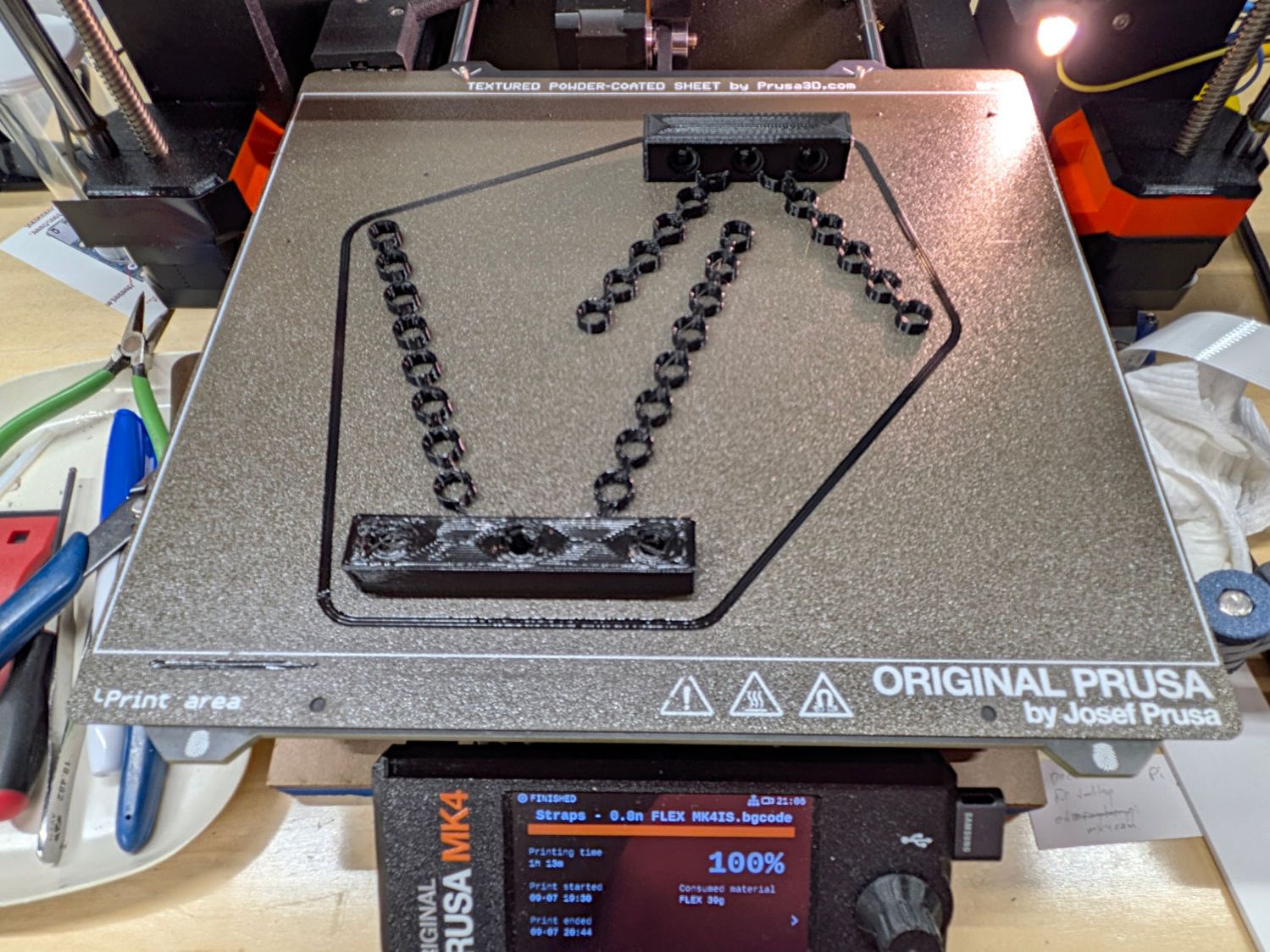
Those are the same stretchy TPU straps, with an additional link on each rear chain to compensate for the slightly higher block mount and a slightly narrower front block to fit in the slightly narrower drawer handle:
Bike Rack Tray Holder – half-width drawer straps
Of course, the only way to know what didn’t fit was to make a pair of the original ones, try them on for size, then adapt the OpenSCAD code accordingly.
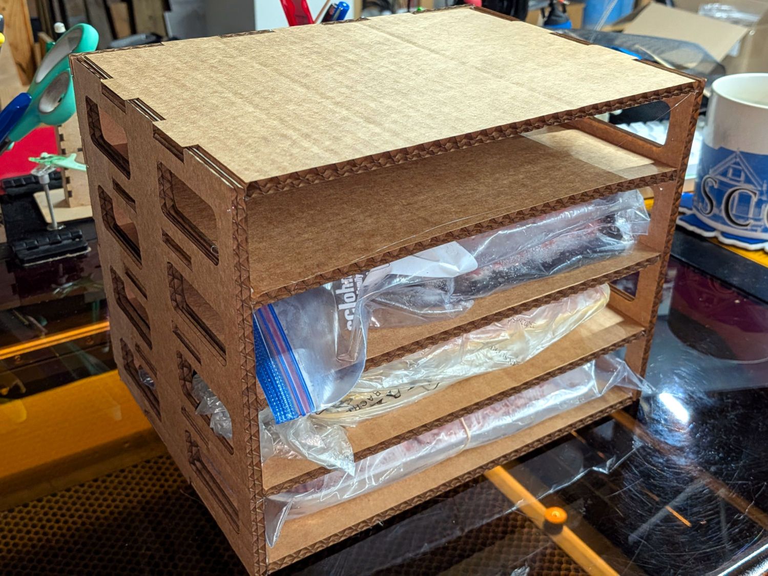
The new chest freezer’s interior has a rectangular lump on the right side over the compressor, atop which we’d been stacking foam trays of ground meat. To forestall a tragic landslide, I made a quick-n-easy rack held together with hot-melt glue:
Freezer Tray Rack – test fit
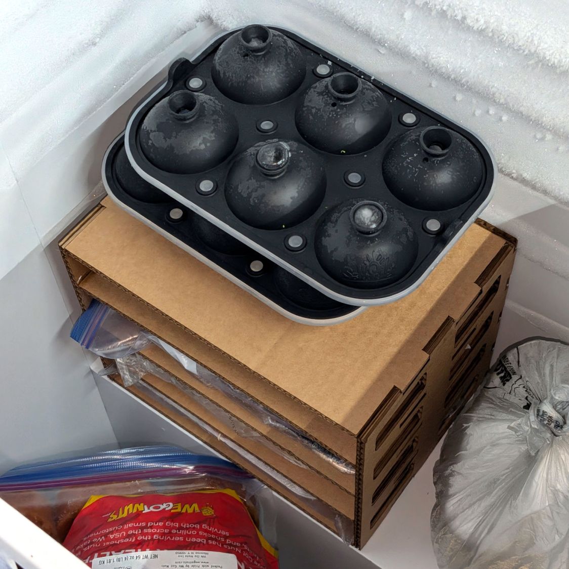
It doesn’t look like it grew there, but it’ll suffice:
Freezer Tray Rack – installed
The weird black things are silicone molds for 4 fl. oz. ice balls (known in these parts as “iceteroids”) suited for chilling the water used to quench veggies after steaming / blanching, prior to freezing.
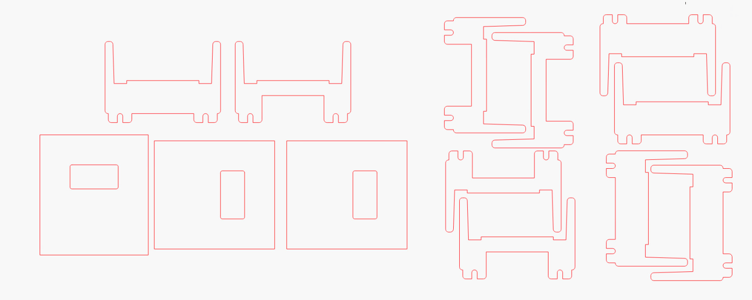
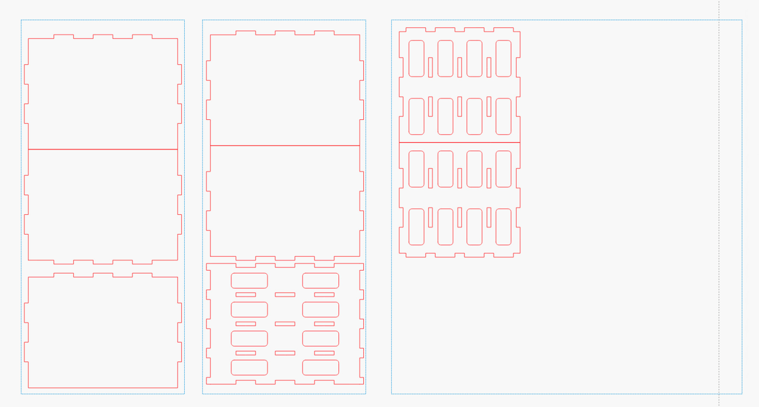
The LightBurn layout arranges the parts in tool-layer rectangles matching a shipping box of 6.5 mm cardboard rugged enough for at least a prototype:
Freezer Tray Rack – LightBurn layout
The jawbreaker boxes.py URL adds 5 mm to the shelf height for a little more clearance. You’ll likely have different cardboard in your stockpile, so tweak as needed, add vent holes in the sides & back, and Fire The Laser.
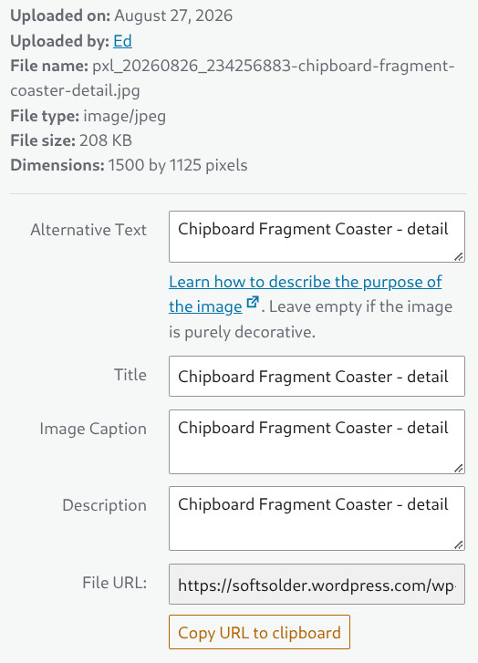
Button 3 on the tablet fills in the fields for WordPress media images:
WordPress Media Fields
Which start out with only the Title field prefilled with the name I created when I saved the file:
PXL_20260826_234256883 - Chipboard Fragment Coaster - detail.jpg
I highlight everything to the left of “Chipboard” and tap Button 3 to fire this series of keystrokes into the browser to cut the highlighted file name, then copy-n-paste everything else into the other three fields:
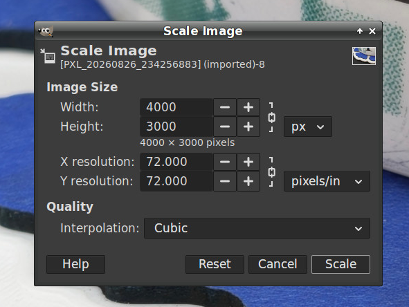
Part of creating those image files in GIMP involves cropping the file to a standard aspect ratio (4:3, 16:9, rarely 32:9 for really skinny images), then scaling to make the widest / tallest edge 1500 pixels with this dialog (invoked by the * key on the numeric keypad):
GIMP Scale Image fields
For unknown reasons, Pixel 10a phone cameras have reverted to 72 DPI images, rather then the previous 300 DPI. Because some programs / browsers / whatever set the physical image size by dividing the number of pixels by the DPI, I prefer to set those fields to 300 DPI.
So click to put the cursor in the widest field, then hit Button 4 to fill in the rest with these keystrokes:
Fortunately, the Resolution fields are locked, so filling in either one sets the other to match, and the keystrokes work correctly in either the Width or Height field.
For unknown reasons, the Huion tablet appears once in the lsusb listing:
Bus 001 Device 017: ID 256c:006d HUION Huion Tablet
But dmesg shows many variations:
[    2.826523] input: HUION Huion Tablet Pen as /devices/pci0000:00/0000:00:14.0/usb1/1-4/1-4.2/1-4.2:1.0/0003:256C:006D.0004/input/input15
[    2.826632] input: HUION Huion Tablet Pad as /devices/pci0000:00/0000:00:14.0/usb1/1-4/1-4.2/1-4.2:1.0/0003:256C:006D.0004/input/input16
[    2.826723] input: HUION Huion Tablet Touch Strip as /devices/pci0000:00/0000:00:14.0/usb1/1-4/1-4.2/1-4.2:1.0/0003:256C:006D.0004/input/input17
[    2.826816] input: HUION Huion Tablet Dial as /devices/pci0000:00/0000:00:14.0/usb1/1-4/1-4.2/1-4.2:1.0/0003:256C:006D.0004/input/input18
[    2.826941] uclogic 0003:256C:006D.0004: input,hidraw11: USB HID v1.11 Keypad [HUION Huion Tablet] on usb-0000:00:14.0-4.2/input0
[    2.834767] uclogic 0003:256C:006D.0005: hidraw4: USB HID v1.11 Device [HUION Huion Tablet] on usb-0000:00:14.0-4.2/input1
Those devices (endpoints, whatever) change as various other USB devices get plugged / unplugged / enumerated:
12986.011937] usb 1-4.2: USB disconnect, device number 16
[12986.359640] usb 1-4.2: new full-speed USB device number 17 using xhci_hcd
[12986.579858] usb 1-4.2: New USB device found, idVendor=256c, idProduct=006d, bcdDevice= 1.00
[12986.579876] usb 1-4.2: New USB device strings: Mfr=1, Product=2, SerialNumber=3
[12986.579882] usb 1-4.2: Product: Huion Tablet
[12986.579887] usb 1-4.2: Manufacturer: HUION
[12986.642042] input: HUION Huion Tablet Pen as /devices/pci0000:00/0000:00:14.0/usb1/1-4/1-4.2/1-4.2:1.0/0003:256C:006D.0014/input/input50
[12986.642609] input: HUION Huion Tablet Pad as /devices/pci0000:00/0000:00:14.0/usb1/1-4/1-4.2/1-4.2:1.0/0003:256C:006D.0014/input/input51
[12986.643357] input: HUION Huion Tablet Touch Strip as /devices/pci0000:00/0000:00:14.0/usb1/1-4/1-4.2/1-4.2:1.0/0003:256C:006D.0014/input/input52
[12986.643699] input: HUION Huion Tablet Dial as /devices/pci0000:00/0000:00:14.0/usb1/1-4/1-4.2/1-4.2:1.0/0003:256C:006D.0014/input/input53
[12986.644245] uclogic 0003:256C:006D.0014: input,hidraw0: USB HID v1.11 Keypad [HUION Huion Tablet] on usb-0000:00:14.0-4.2/input0
[12986.707886] uclogic 0003:256C:006D.0015: hidraw1: USB HID v1.11 Device [HUION Huion Tablet] on usb-0000:00:14.0-4.2/input1
[14148.081803] input: HUION Huion Tablet Pad as /devices/virtual/input/input55
On some occasions, based on no events I understand, input-remapper will recognize the tablet as any one of:
drwxr-xr-x  2 ed ed 4.0K Feb 18  2025 'HUION Huion Tablet'/
drwxr-xr-x  2 ed ed 4.0K Sep  1 10:43 'HUION Huion Tablet Pad'/
drwxr-xr-x  2 ed ed 4.0K Apr  3  2024 'HUION Huion Tablet Pen'/
The dates show it’s been ‘HUION Huion Tablet Pad’ for a while, but ya never know what tomorrow will bring.
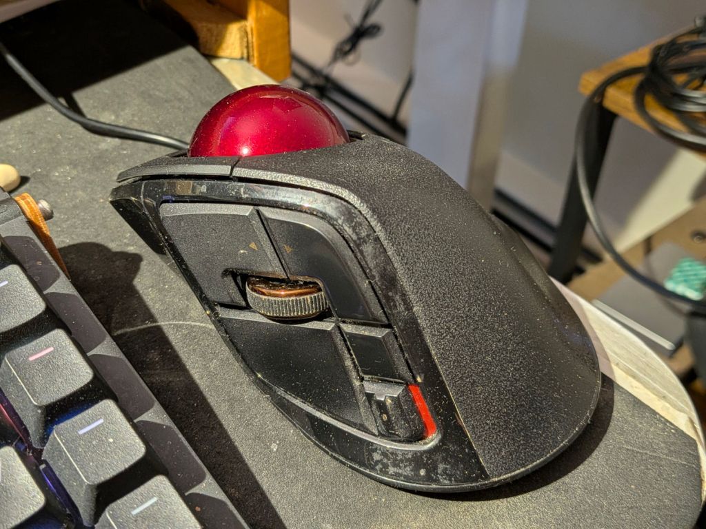
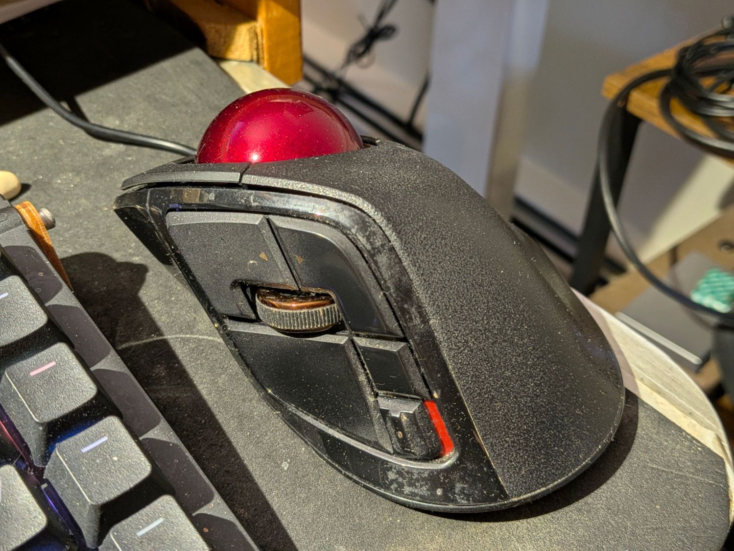
The Elecom Deft Pro trackball at my right hand has seven buttons (three hidden around the ball) and a scroll wheel with up-down switches (called Wheel Right and Wheel Left from their horizontal mouse ancestry):
Elecom Deft Pro trackball
Yeah, I oughta scrub that puppy more often.
The wheel up-down switches map to the Home and End keys with the Ctrl key held down to jump to the beginning and end of the page:
KEY_LEFTCTRL+KEY_HOME
KEY_LEFTCTRL+KEY_END
The wheel also has a push switch (the Middle mouse button) that I find inconvenient, so Button 6 (labeled Fn1 on the button) under my forefinger does that:
BTN_MIDDLE
Closing a browser tab happens so often it’s mapped to the small square button just over the resolution slide switch where my thumb can hit it:
Slightly modify the OpenSCAD code to suit thinner chipboard:
include <BOSL2/std.scad>

fn = "Printed Fragment Coaster - 5 in Set B - Inkscape paths.svg";

FragmentThick = 0.8;

BaseThick = 2.0;
RimHeight = 0.4;

union() {


  linear_extrude(h=BaseThick)
    import(fn,id="Perimeter");

  color("Green")
    up(BaseThick)
      linear_extrude(h=FragmentThick)
        difference() {
          import(fn,id="Perimeter");
          import(fn,id="Recesses");
        }

  color("Red")
    up(BaseThick + FragmentThick)
    linear_extrude(h=RimHeight)
      difference() {
        import(fn,id="LipOut");
        import(fn,id="LipIn");
        import(fn,id="Island");
      }

}
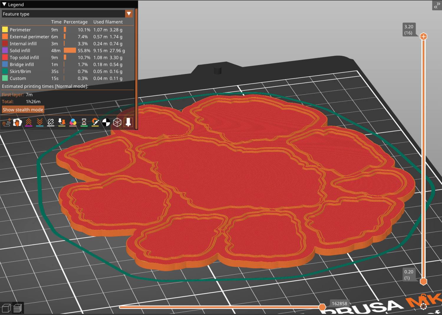
Run the solid model through PrusaSlicer:
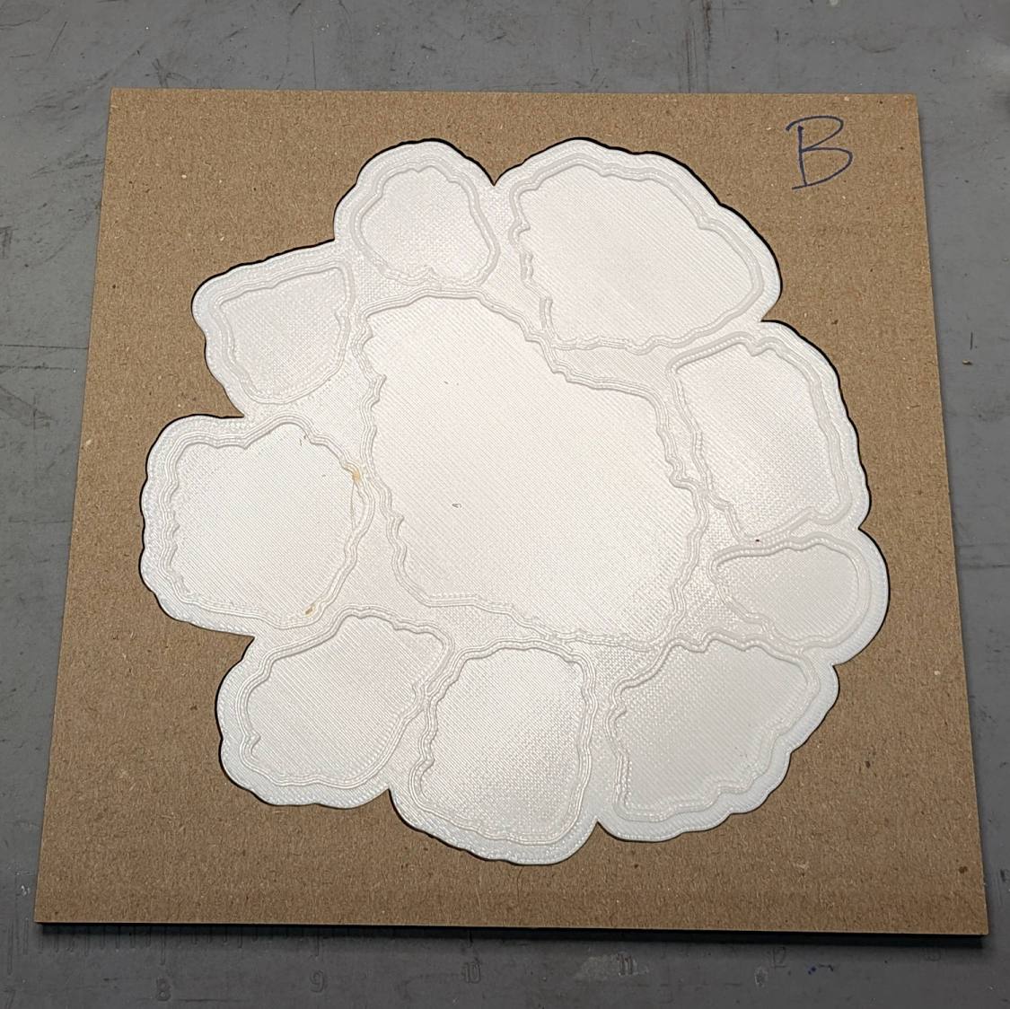
Chipboard Fragment Coaster B – slicer preview
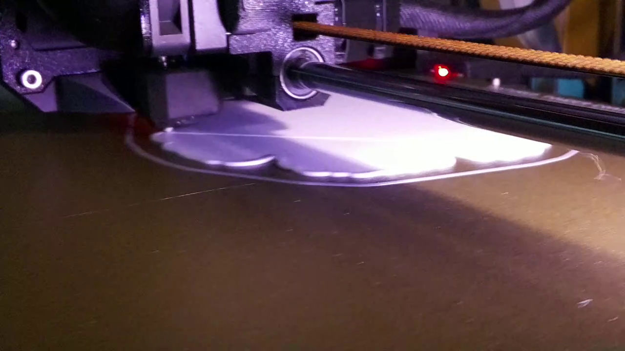
And have a baseplate an hour later:
Coaster Printing – in progress
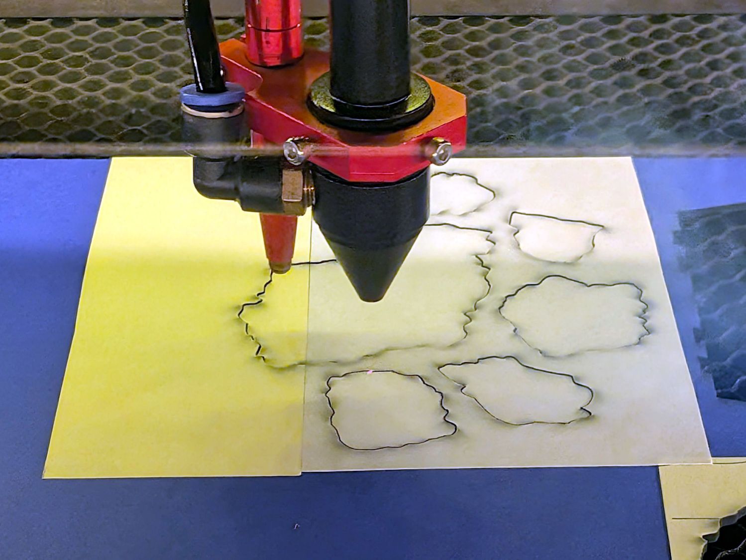
While that’s buzzing away, tell LightBurn to cut chipboard instead of metallized paper, stick some craft adhesive sheet on the chipboard, and Fire The Laser:
Chipboard Fragment Coaster – chipboard cutting
Remember to mirror the fragments, because you’re cutting them bottom-up.
Do the same for the cork sheet going on the bottom, which does not require mirroring.
I tossed the cardboard alignment fixtures I used to stick the cork onto the 3D printed baseplate, so make another one for each coaster.
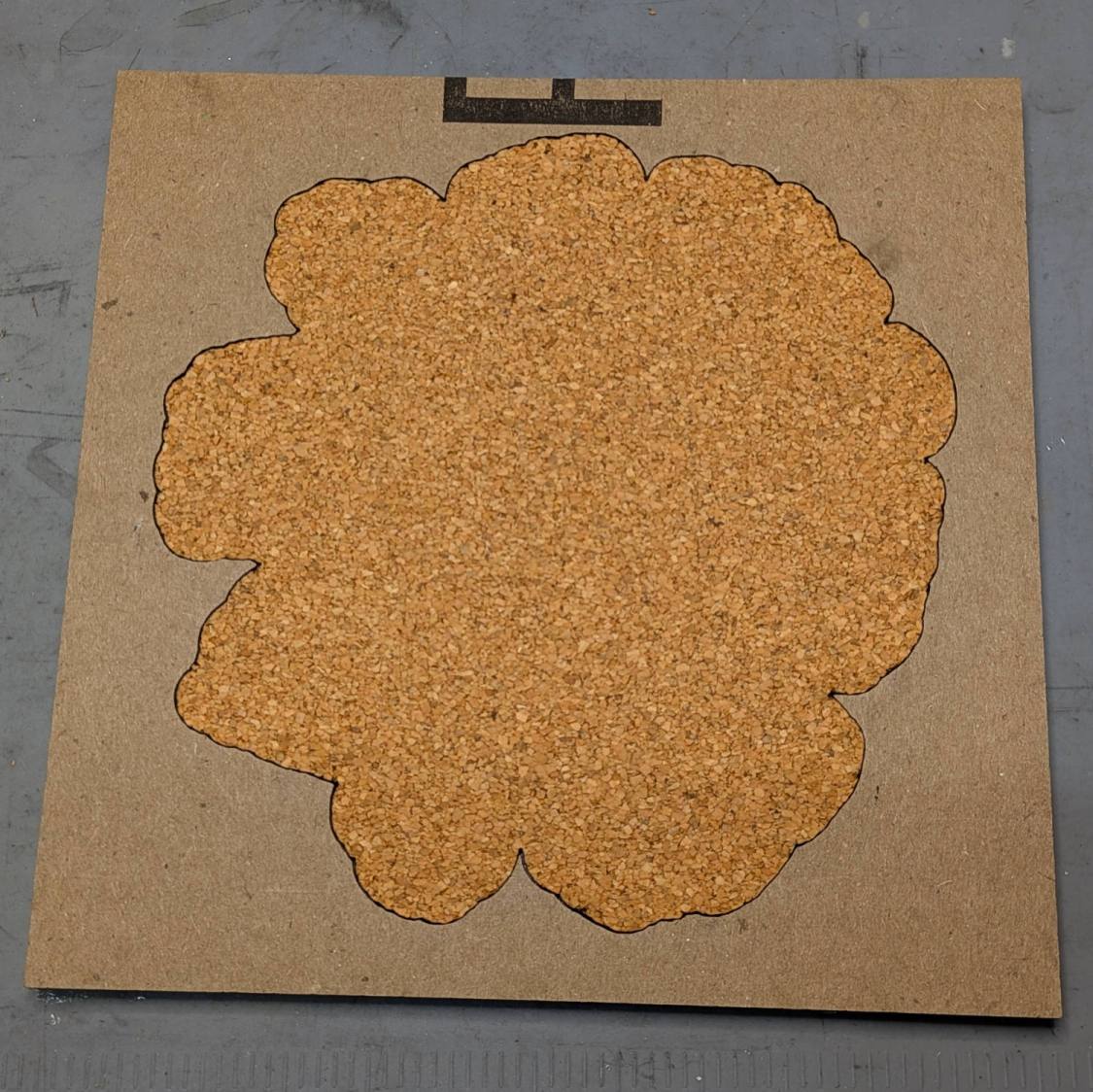
The top layer holds the baseplate:
Chipboard Fragment Coaster – cork fixture – top
The cork + adhesive sheet is inset 0.5 mm from the edge of the baseplate, so the outline cut in the bottom layer of cardboard is just that much smaller:
Chipboard Fragment Coaster – cork fixture – bottom
Although the time used to make a fixture isn’t deducted from your allotment, I’m not sure about making two identical fixtures, so I’m saving these for the next time.
Then peel-n-stick the chipboard fragments in their recesses:
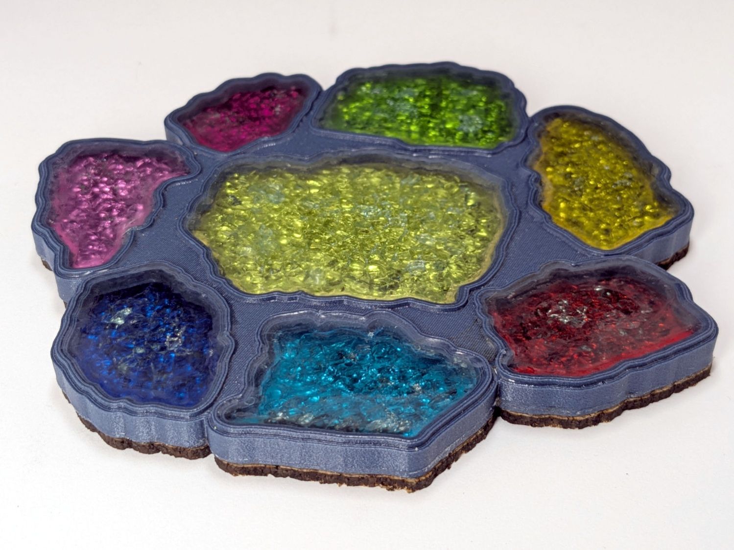
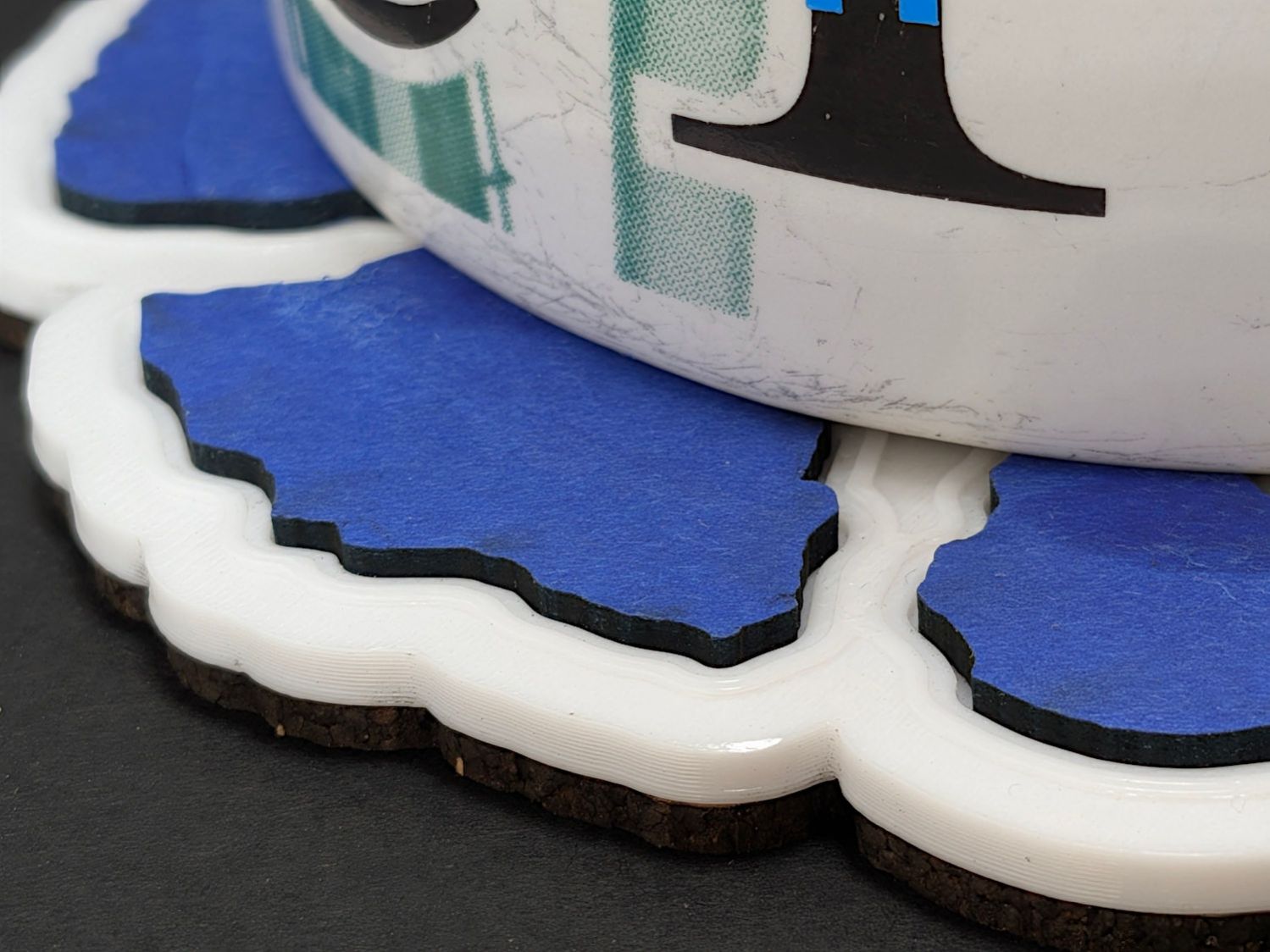
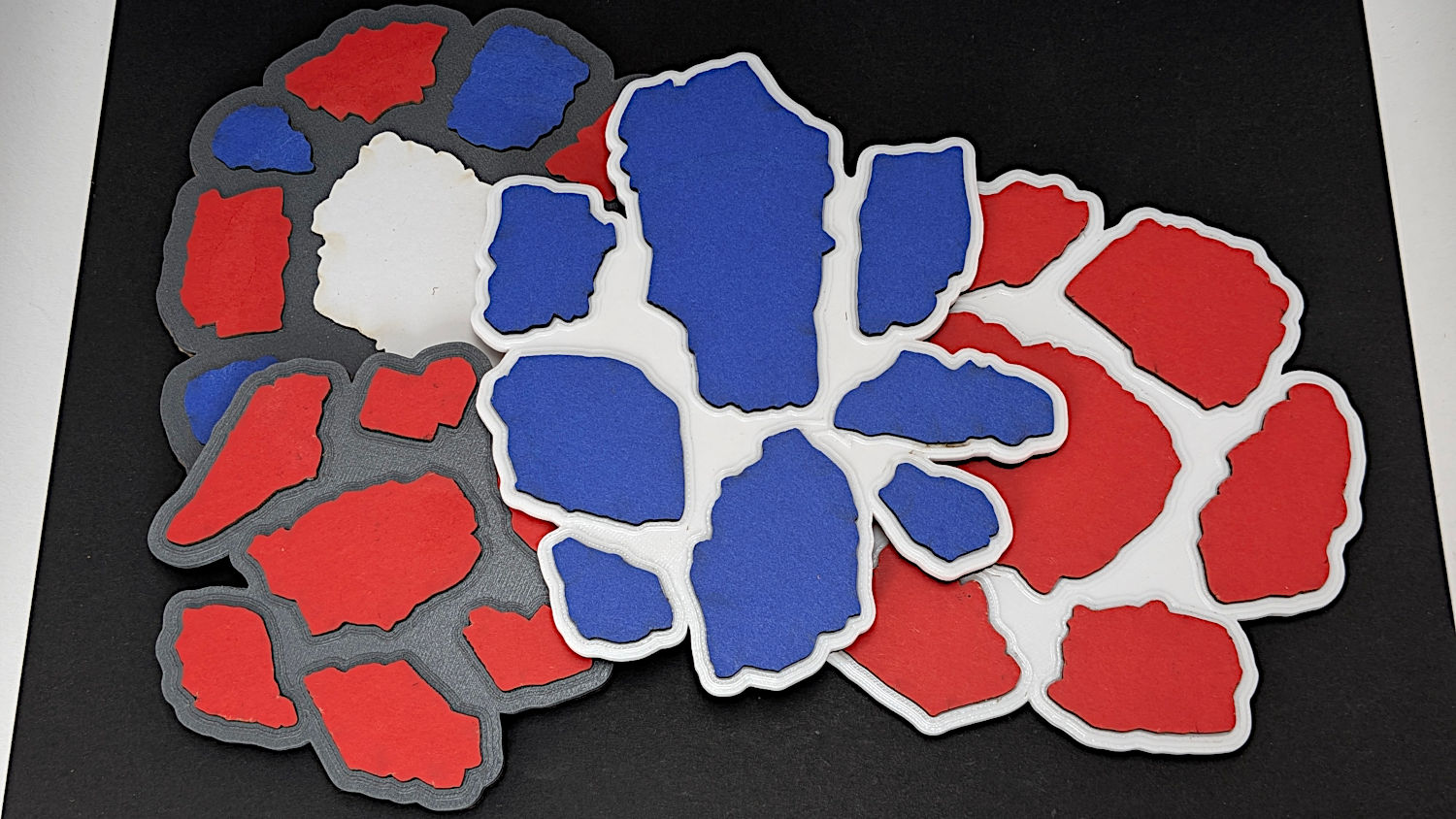
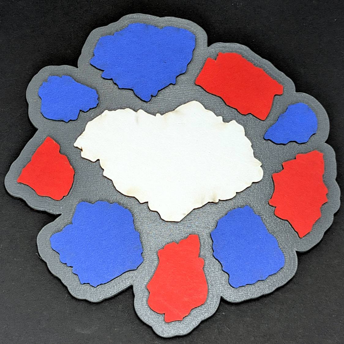
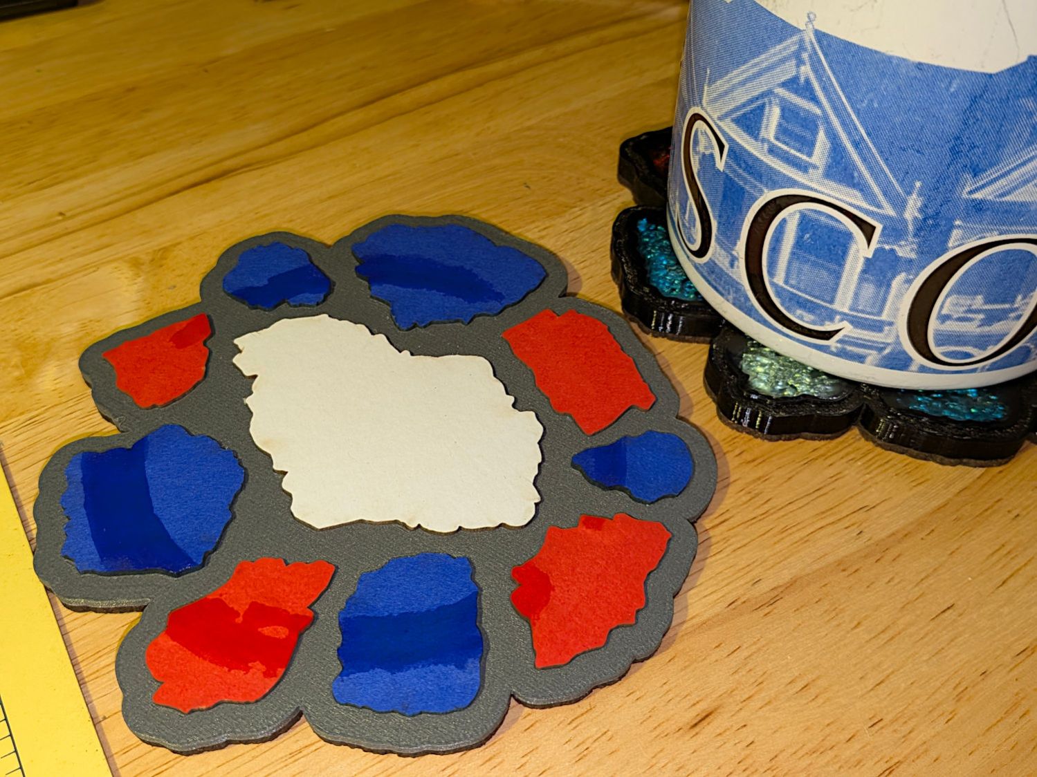
Chipboard Fragment Coaster – variety
The first baseplate didn’t have raised rims around the fragments (because there’s no need to retain any epoxy), but the result looked kinda … flat:
Chipboard Fragment Coaster – flat top
Fixing that was a matter of not setting the rim height to zero in the OpenSCAD code.
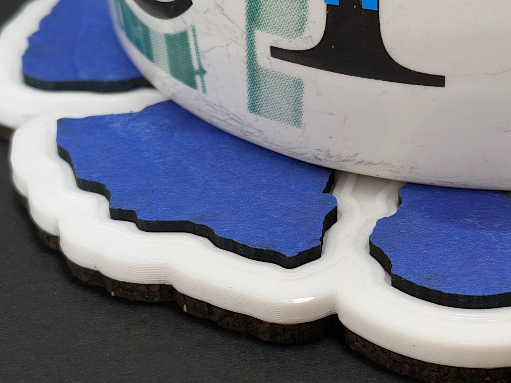
It’s perfectly functional even without a rim:
Printed Coaster – chipboard inserts – sweaty mug
Protip: White chipboard is a Terrible Idea™ in a quick-n-easy laser cuttery project. All the rest have only red or blue fragments for a good reason.
Conversely, white PETG makes a nice contrast to the deep red and blue.
Tomato Canning season has returned and my puny contributions involve maneuvering large pots of boiling water and, this time, cleaning up corrosion under the lid knob.
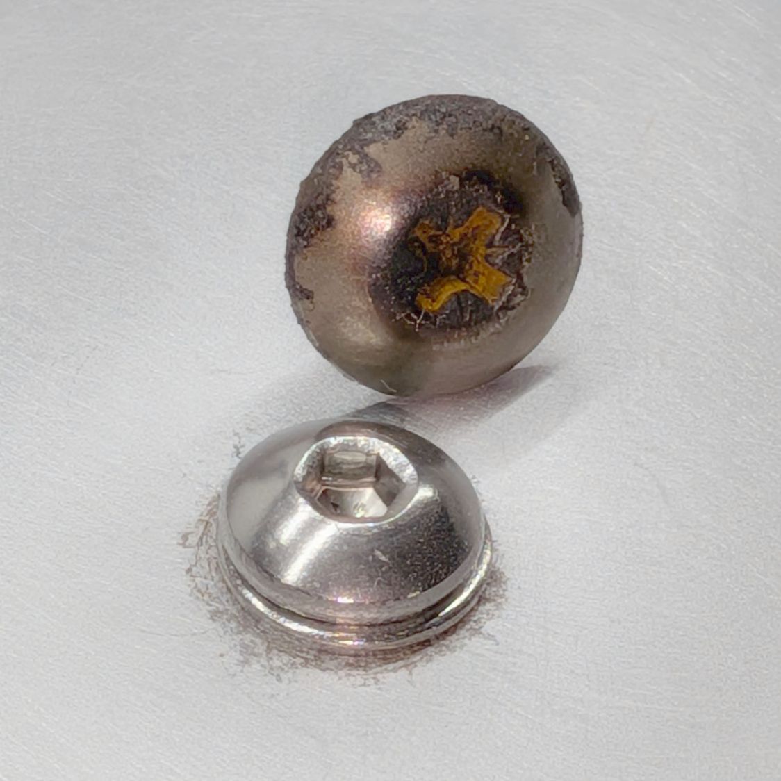
The corroded OEM screw vs. the shiny stainless steel screw:
Canning pot lid knob – OEM vs new screw
The dark rim under the washer remained after hitting the area with sanding pad grits from 320 up through 1200, which seemed sufficient.
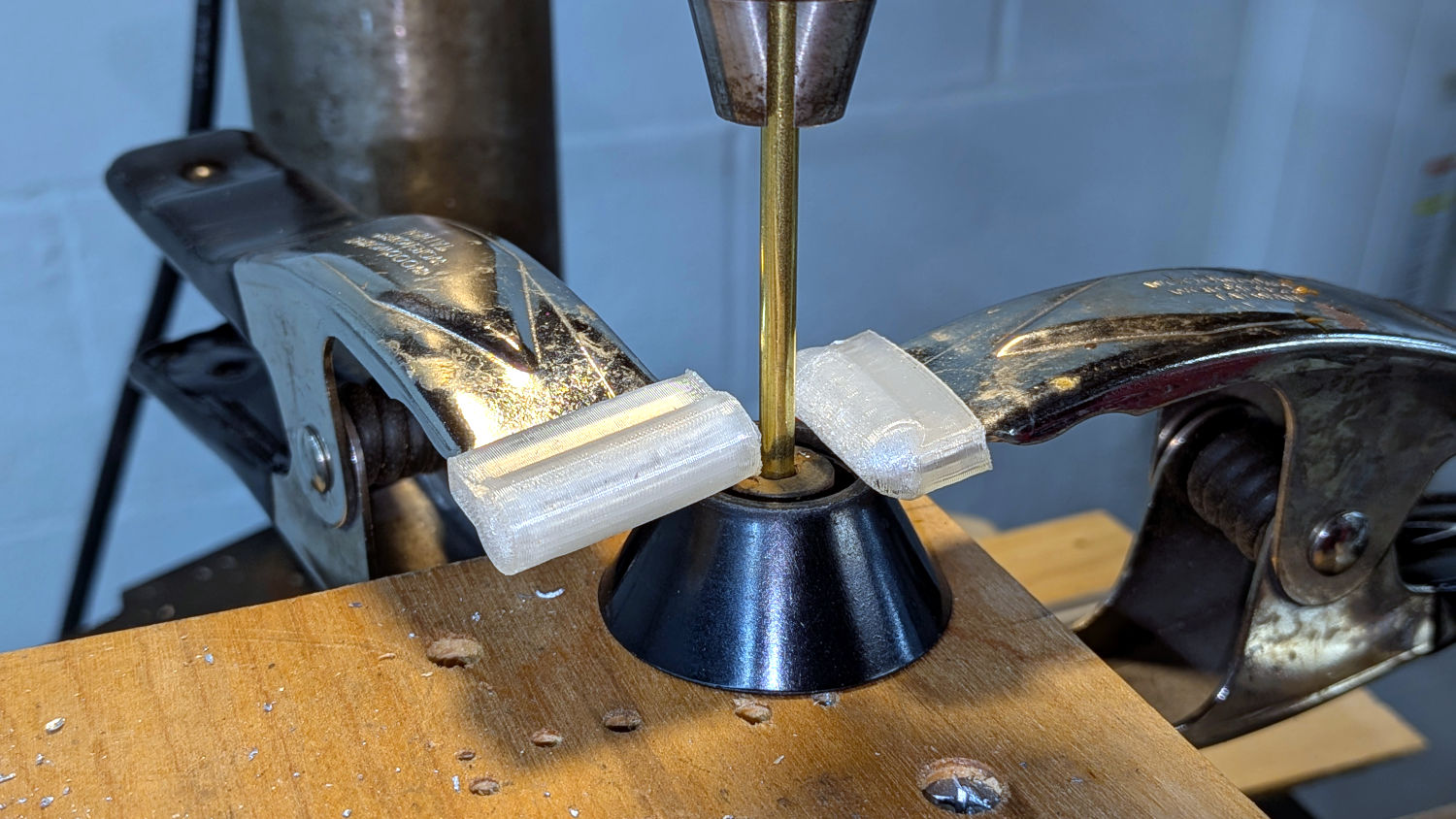
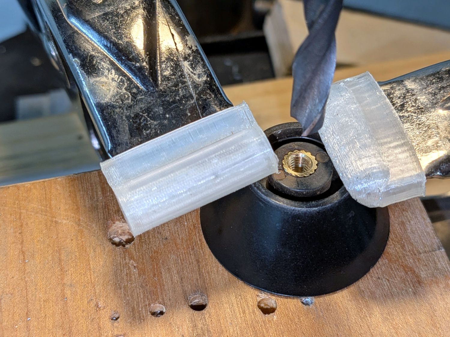
The OEM screw had a self-tapping thread, but I’d rather use a machine screw with an insert. Start by lining up the existing screw hole on the drill press and clamping the knob firmly in position:
Canning pot lid knob – hole alignment
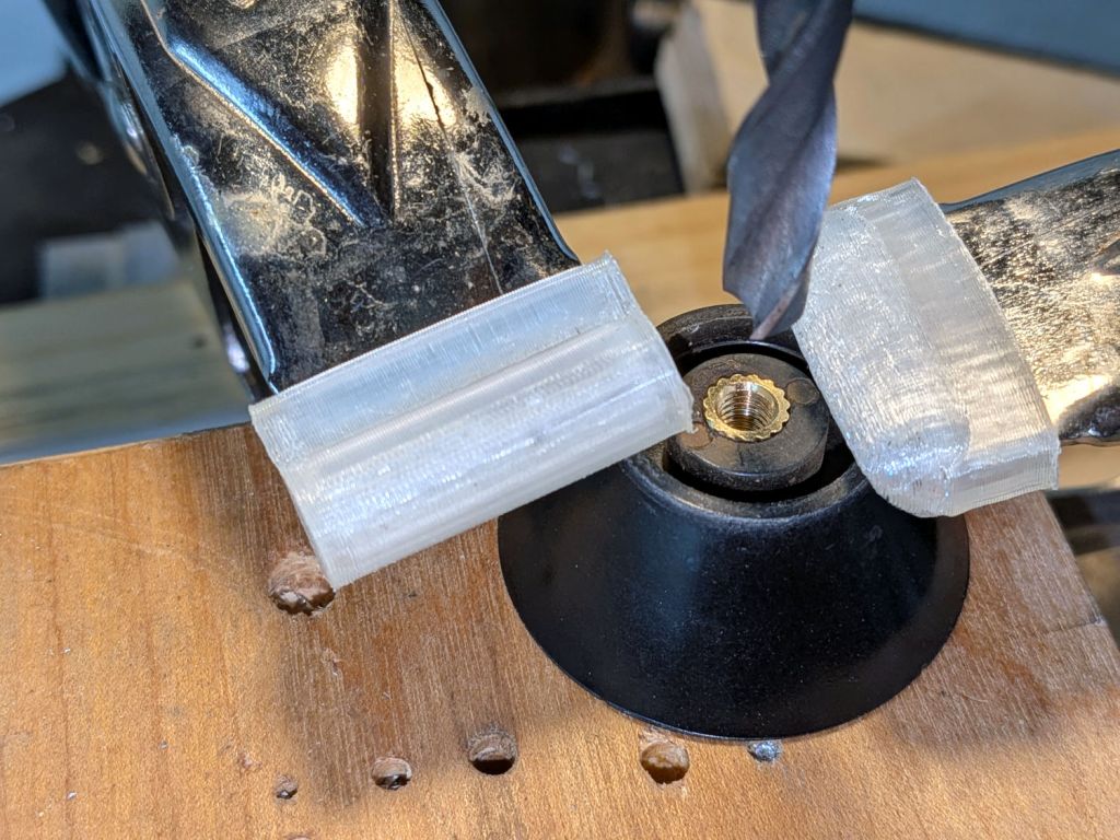
Then drill to fit an M5 brass insert, while testing the hole depth:
Canning pot lid knob – insert test fit
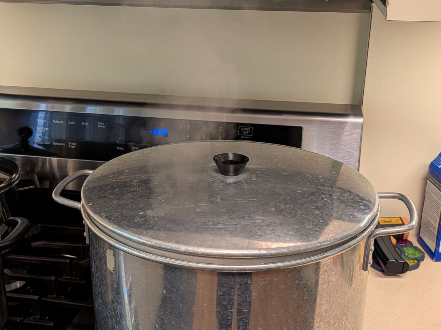
Slather the insert with JB Weld epoxy, seat it in the hole, cure overnight, assemble in reverse order, and the lid was ready for the next canning session:
Canning pot lid handle – in use
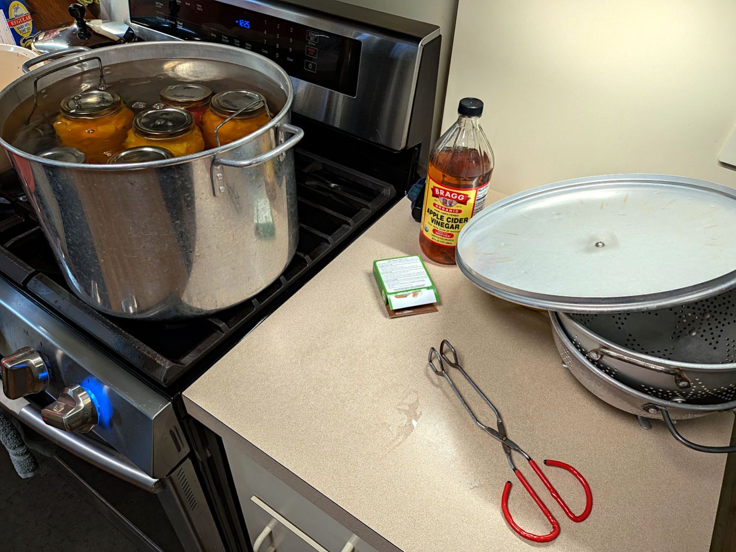
Yes, those are jars. The process is called canning: