Ed Nisley's Blog: Shop notes, electronics, firmware, machinery, 3D printing, laser cuttery, and curiosities. Contents: 100% human thinking, 0% AI slop.
Tag: Improvements
Making the world a better place, one piece at a time
Last month’s basement safe log showed the humidity (blue trace) relentlessly rising:
Basement Safe – 2015-08-09
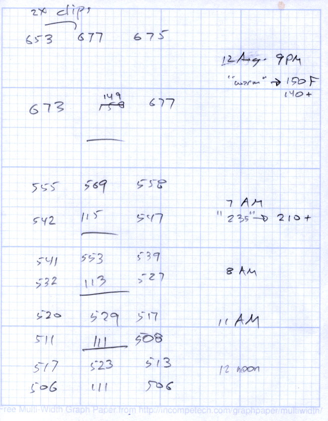
Replacing that bag emptied the dried silica gel stash, so I piled six saturated bags in the oven for an overnight regeneration with the oven set to “Warm”, which the IR thermometer reported as 140 °F or so at the bag surface. They sat on cooling racks atop cookie sheets that pretty much filled two oven shelves, with good air flow across their tops and minimal flow between bags and cookie sheet.
The last time around, I spread the beads directly on the cookie sheets. That seemed like a lot of effort, so I wanted to see how the low-labor alternative worked.
The two upper-left bags in each group had a pair of bulldog clips holding them closed. The larger bags hold 500 g of “dry” silica gel and the center bag in the lower row was a smaller mesh bag:
Silica Gel drying – 2015-08-12
The big bags lost a bit under 130 g during 10 hours, call it 12 g/h, and felt slightly damp on their lower surface.
I cranked the oven to 230 °F, the lowest actual heat setting, for 210 °F on the bag surface. That got rid of the last 30 g in three hours; another hour brought them to pretty nearly their dry weight of 507 g (gross, with bag / staples / clips).
Drying being an exponential process, it looks like an overnight bake at “230 °F” will do the trick without melting the bags; the lower temperature doesn’t quite get the job done.
Thinwall open boxes – side detail – 4.98 4.85 measured
Alas, the shutter failed after that image, leaving me with pictures untaken and naught to take them with.
The least-awful alternative seems to be gimmicking up an adapter for a small USB camera from the usual eBay source:
Fashion USB video – case vs camera
The camera’s 640×480 VGA resolution is marginally Good Enough for the purpose, as I can zoom the microscope to completely fill all those pixels. The optics aren’t up to the standard set by the microscope, but we can cope with that for a while.
A bit of doodling & OpenSCAD tinkering produced a suitable adapter:
USB Camera Microscope Mount – solid model
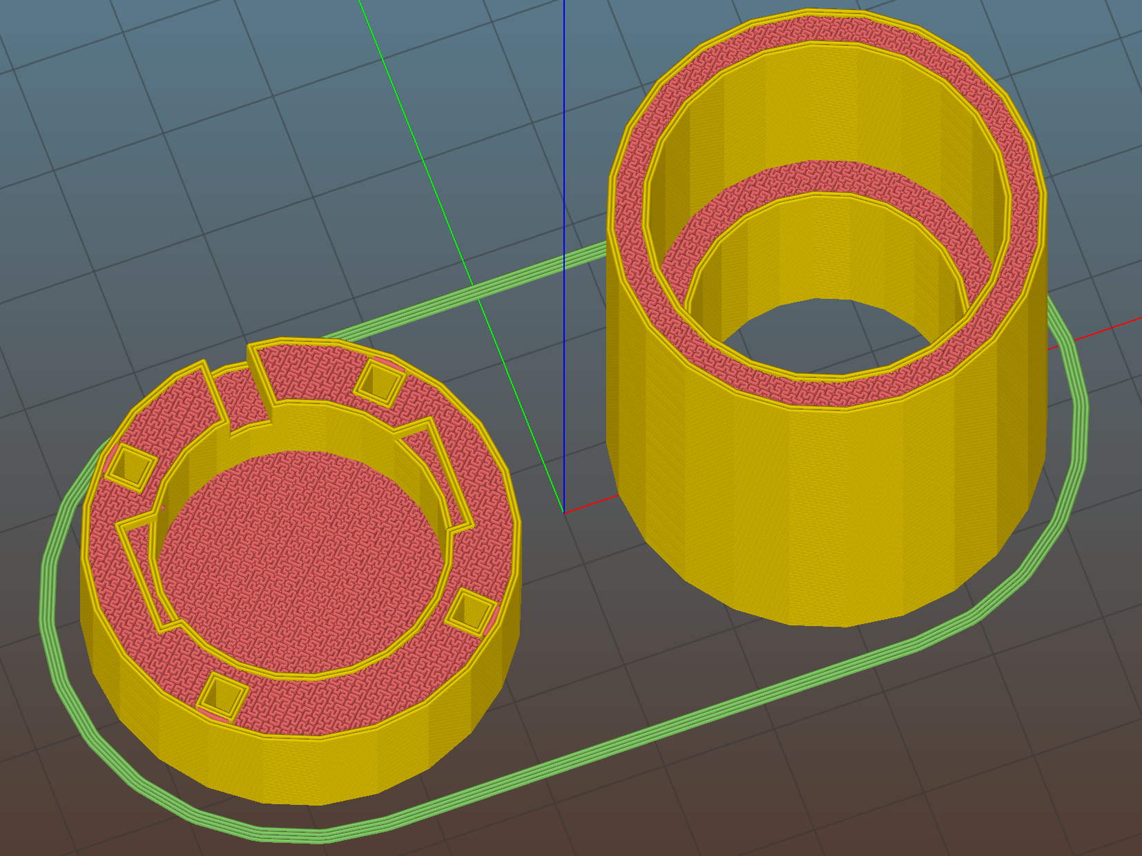
To which Slic3r applied the usual finishing touches:
USB Camera Microscope Mount – Slic3r preview
A bit of silicone tape holds the sloppy focusing thread in place:
USB Camera Microscope Mount – cap with camera
Those are 2-56 screws that will hold the cap onto the tube. I drilled out the clearance holes in the cap and tapped the holes in the eyepiece adapter by hand, grabbing the bits with a pin vise.
Focus the lens at infinity, which in this case meant an old DDJ cover poster on the far wall of the Basement Laboratory, and then it’ll be just as happy with the image coming out of the eyepiece as a human eyeball would be.
I put a few snippets of black electrical tape atop the PCB locating tabs before screwing the tube in place. The tube ID is 1 mm smaller than the PCB OD, in order to hold the PCB perpendicular to the optical axis and clamp it firmly in place. Come to find out that the optical axis of the lens isn’t perfectly perpendicular to the PCB, but it’s close enough for my simple needs.
And then it fits just like you’d expect:
USB Camera Microscope Mount – on eyepiece
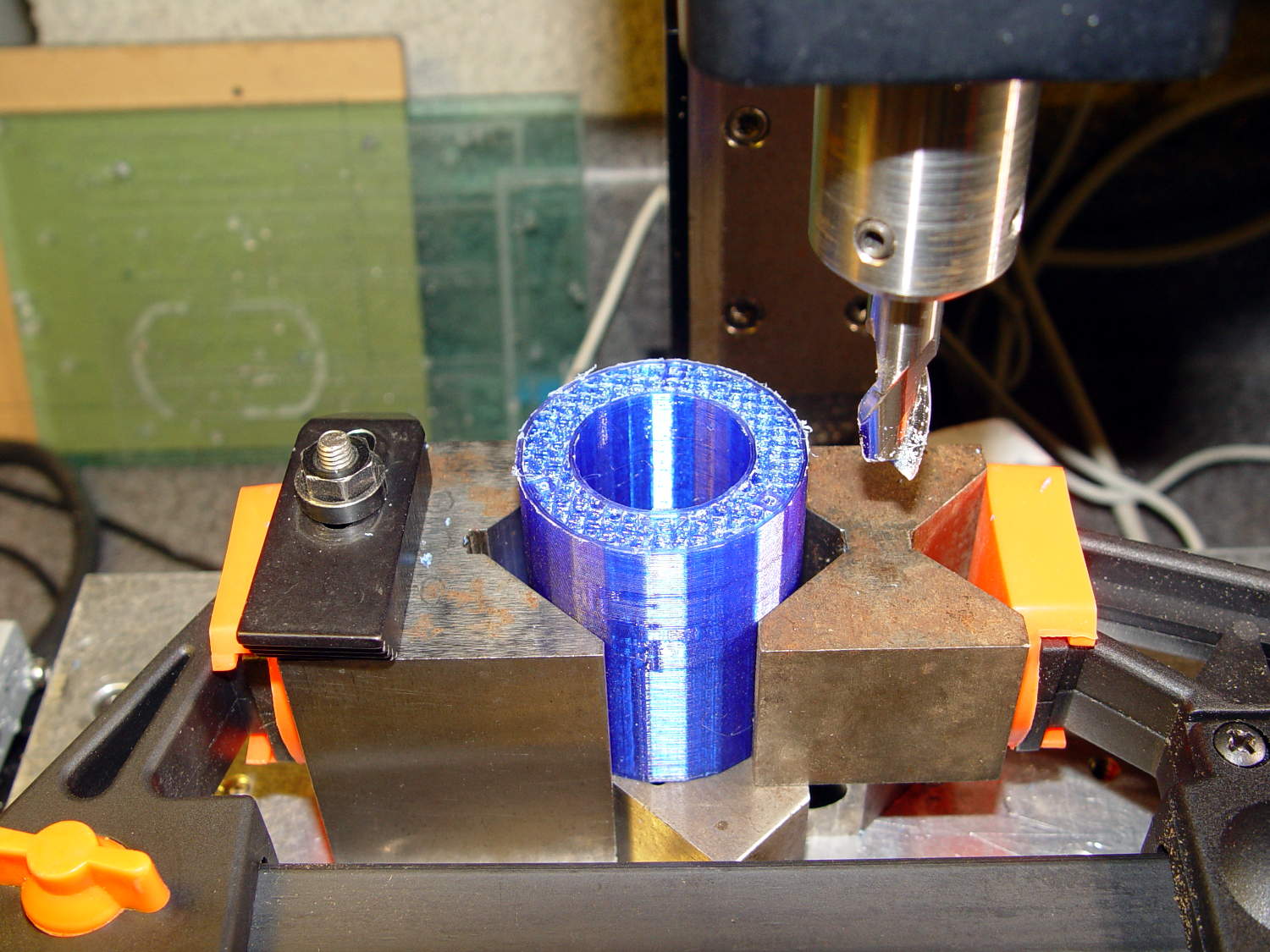
Actually, that’s the second version. The distance from the camera lens (equivalently: the PCB below the optical block, which I used as the datum plane) to the eyepiece is a critical dimension that determines whether the image fills the entrance pupil. I guesstimated the first version by hand-holding the camera and measuring with a caliper, tried it out, then iteratively whacked 2 mm off the tube until the image lit up properly:
USB Camera Microscope Mount – adjusting tube length
Minus 4 mm made it slightly too short, but then I could measure the correct position, tweak that dimension in the code, and get another adapter, just like the first one (plus a few other minor changes), except that it worked:
USB Camera Microscope Mount – first light
That’s a screen capture from VLC, which plays from /dev/video0 perfectly. Some manual exposure & color balance adjustment may be in order, but it’s pretty good for First Light.
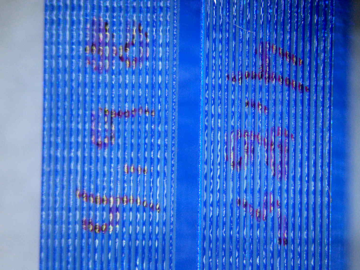
It turns out that removing the eyepiece and holding the bare sensor over the opening also works fine. The real image from the objective fills much more area than the camera’s tiny sensor: the video image covers about one digit in that picture, but gimmicking up a bare-sensor adapter might be useful.
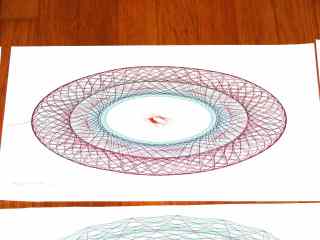
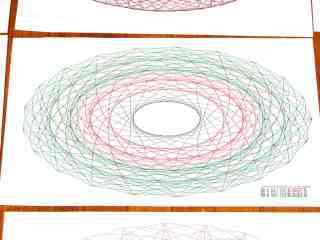
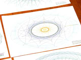
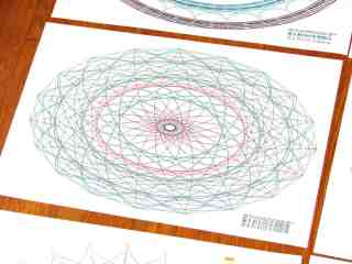
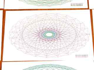
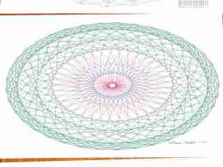
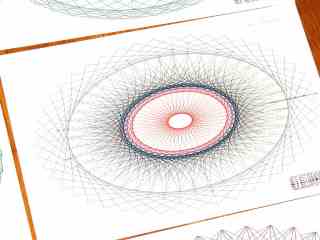
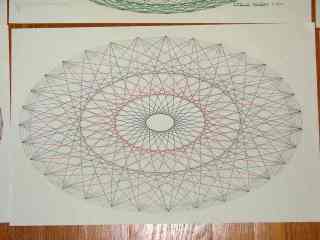
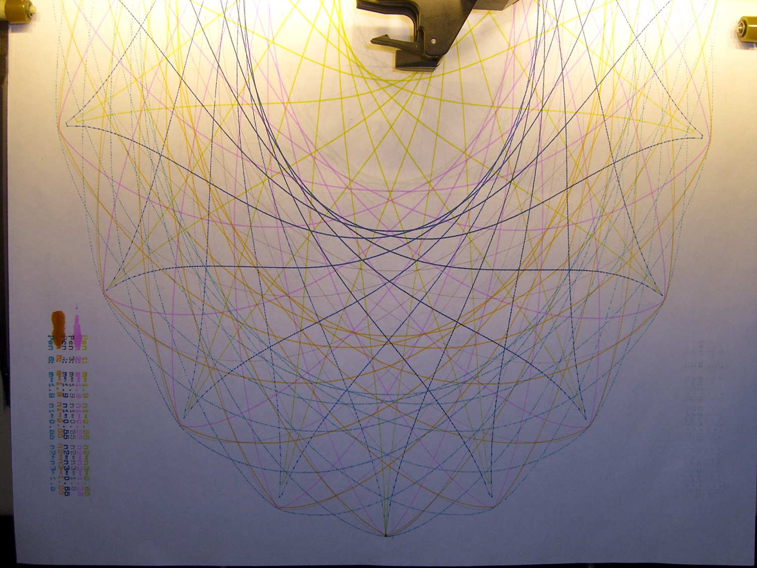
A gallery of SuperFormula plots, resized / contrast stretched / ruthlessly compressed (clicky for more dots):
SuperFormula Plot – 01
SuperFormula Plot – 02
SuperFormula Plot – 03
SuperFormula Plot – 04
SuperFormula Plot – 05
SuperFormula Plot – 06
SuperFormula Plot – 07
SuperFormula Plot – 08
SuperFormula Plot – 09
SuperFormula Plot – 10
SuperFormula Plot – 11
SuperFormula Plot – 12
SuperFormula Plot – 13
SuperFormula Plot – 14
SuperFormula Plot – 15
The gray one at the middle-bottom suffered from that specular reflection; the automagic contrast stretch couldn’t boost the paper with those burned pixels in the way.
Those sheets all have similar plots on the back, some plots used refilled pens that occasionally bled through the paper, others have obviouslybad / dry pens, and you’ll spot abrupt color changes where I swapped out a defunct pen on the fly, but they should give you an idea of the variations.
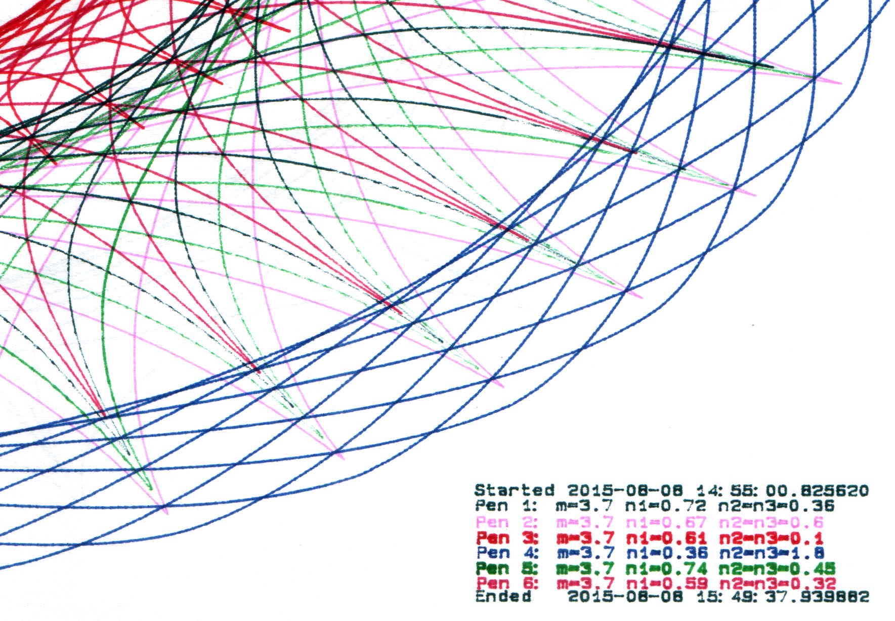
The more recent plots have a legend in the right bottom corner with coefficients and timestamps:
SuperFormula Plot – legend detail
Limiting the pen speed to 10 cm/s (down from the default 38.1 cm/s = 15.00 inch/s) affects only the outermost segments of the spikes; down near the dense center, the 9600 b/s serial data rate limits the plotting speed. Plotting slowly helps old pens with low flow rates draw reasonably dense lines.
Each plot takes an hour, which should suffice for most dog-and-pony events.
I fill a trio of Python lists with useful coefficient values, then choose random elements for each plot: a single value of m determines the number of points for all six traces, then six pairs of values set n1 and n2=n3. The lists are heavily weighted to produce spiky traces, rather than smooth ovals, so the “random” list selections aren’t uniformly distributed across the full numeric range of the values.
Because the coefficient lists contain fixed values, the program can produce only a finite number of different plots, but I’m not expecting to see any duplicates. You can work out the possibilities by yourself.
The modified Chiplotle demo code bears little resemblance to the original:
from chiplotle import *
from math import *
from datetime import *
import random

def superformula_polar(a, b, m, n1, n2, n3, phi):
   ''' Computes the position of the point on a
   superformula curve.
   Superformula has first been proposed by Johan Gielis
   and is a generalization of superellipse.
   see: http://en.wikipedia.org/wiki/Superformula
   Tweaked to return polar coordinates
   '''

   t1 = cos(m * phi / 4.0) / a
   t1 = abs(t1)
   t1 = pow(t1, n2)

   t2 = sin(m * phi / 4.0) / b
   t2 = abs(t2)
   t2 = pow(t2, n3)

   t3 = -1 / float(n1)
   r = pow(t1 + t2, t3)
   if abs(r) == 0:
      return (0,0)
   else:
 #     return (r * cos(phi), r * sin(phi))
     return (r,phi)


def supershape(width, height, m, n1, n2, n3,
   point_count=10*1000, percentage=1.0, a=1.0, b=1.0, travel=None):
   '''Supershape, generated using the superformula first proposed
   by Johan Gielis.

   - `points_count` is the total number of points to compute.
   - `travel` is the length of the outline drawn in radians.
      3.1416 * 2 is a complete cycle.
   '''
   travel = travel or (10*2*pi)

   ## compute points...
   phis = [i * travel / point_count
      for i in range(1 + int(point_count * percentage))]
   points = [superformula_polar(a, b, m, n1, n2, n3, x) for x in phis]

   ## scale and transpose...
   path = [ ]
   for r, a in points:
      x = width * r * cos(a)
      y = height * r * sin(a)
      path.append(Coordinate(x, y))

   return Path(path)


## RUN DEMO CODE

if __name__ == '__main__':
   paperx = 8000
   papery = 5000
   tscale = 0.45
   numpens = 6
   m_list = [n/10.0 for n in [11, 13, 17, 19, 23, 29, 31, 37, 41, 43, 47, 53, 59]];   # prime/10 = number of spikes
   n1_list = [n/100.0 for n in range(15,75,1) + range(80,120,5) + range(120,200,10)]  # ring-ness 0.1 to 2.0, higher is larger diameter
   n2_list = [n/100.0 for n in range(10,50,1) + range(55,100,5) + range(110,200,10)]  # spike-ness 0.1 to 2.0, lower means spiky points
   paramlist = [[n1,n2] for n1 in random.sample(n1_list,numpens) for n2 in random.sample(n2_list,numpens)]
   if  not False:
     plt=instantiate_plotters()[0]
     plt.write('IN;')
#     plt.write(chr(27) + '.H200:')   # set hardware handshake block size
     plt.set_origin_center()
     plt.write(hpgl.SI(tscale*0.285,tscale*0.375))    # scale based on B size characters
     plt.write(hpgl.VS(10))                           # slow speed for those abrupt spikes
     pen = 1
     plt.select_pen(pen)
     plt.write(hpgl.PA([(paperx - 3000,-(papery - 600))]))
     plt.write(hpgl.LB("Started " + str(datetime.today())))
     m = random.choice(m_list)
     for n1, n2 in zip(random.sample(n1_list,numpens),random.sample(n2_list,numpens)):
        n3 = n2
        print "m: ", m, " n1: ", n1, " n2=n3: ", n2
        plt.write(hpgl.PA([(paperx - 3000,-(papery - 500 + 100*(pen - 1)))]))
        plt.select_pen(pen)
        plt.write(hpgl.LB("Pen " + str(pen) + ": m=" + str(m) + " n1=" + str(n1) + " n2=n3=" + str(n2)))
        e = supershape(paperx, papery, m, n1, n2, n3)
        plt.write(e)
        if pen < numpens:
            pen += 1
        else:
            pen = 1
     pen = 1
     plt.select_pen(pen)
     plt.write(hpgl.PA([(paperx - 3000,-(papery - 500 + 100*numpens))]))
     plt.write(hpgl.LB("Ended   " + str(datetime.today())))
     plt.select_pen(0)
   else:
     e = supershape(paperx, papery, 1.9, 0.8, 3, 3)
     io.view(e)
The blotches on the legend in the lower left corner show that a refilled plotter pen can accumulate a droplet of ink around its nib, which should come as no surprise. I wiped off the excess immediately after refilling each pen, let the assortment sit for a few hours to (presumably) let the new ink reach the nib, and wiped them off before inserting them in the plotter’s pen carousel. All I can say is that I used up a bunch of paper towels in the process…
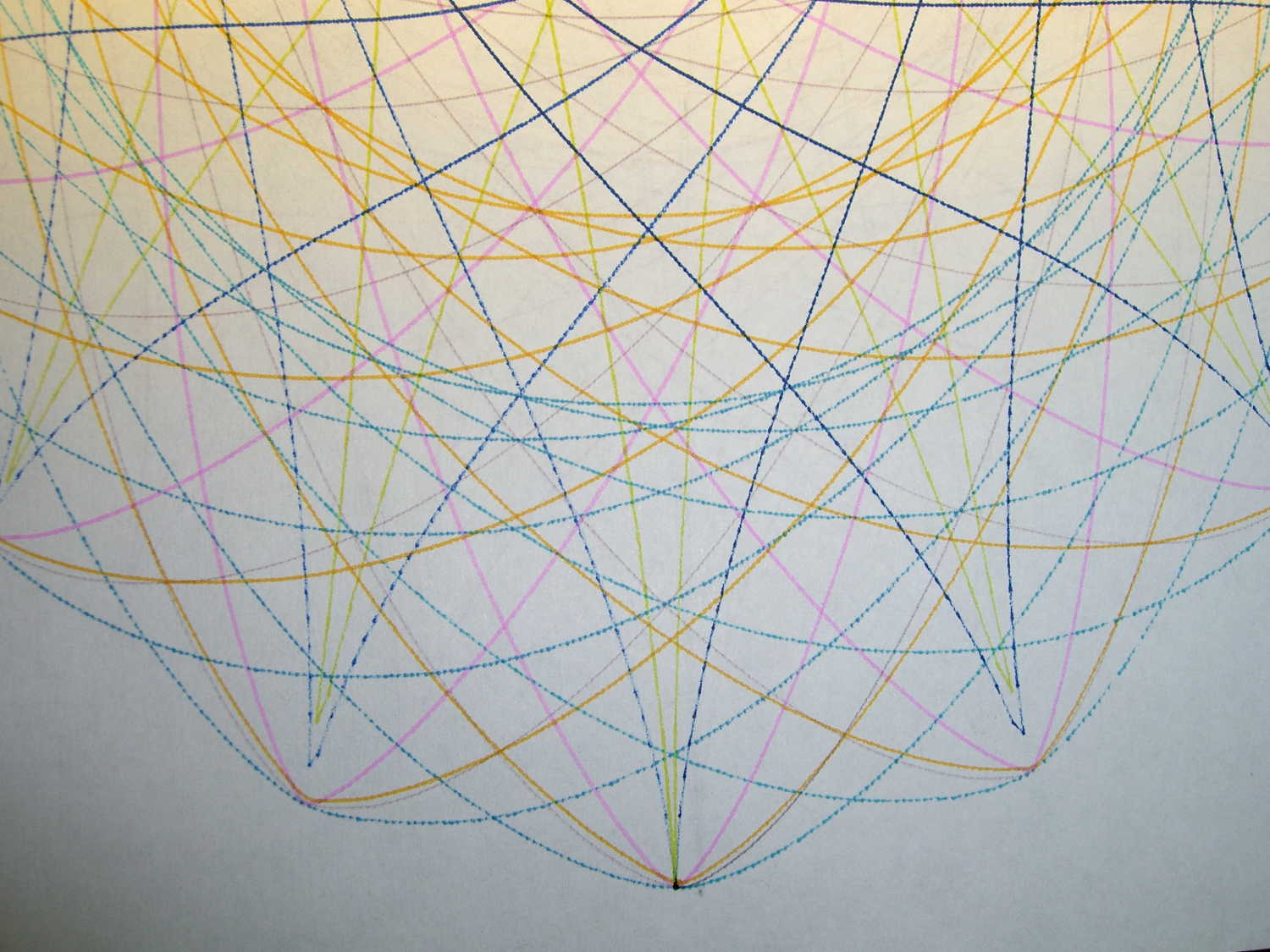
A closer look at the plot shows Pretty Good If You Ask Me results:
CMYK Refilled Pens – plot detail
The two blue-ish pens have less flow than the others, resulting in dotted lines that should be continuous. As nearly as I can tell, that’s a function of how much OEM ink has solidified in the fiber nib and, most likely, the fiber rod that draws ink from the sponge reservoir inside the body.
And, of course, the colors produced by adding CMY printer ink to the surviving OEM ink aren’t found in any catalog. I’m also blithely ignoring the difference between the inks inside plotter pens intended for paper and those for overhead transparencies; at this late date, that’s defined to Not Matter.
Mary flattens seam allowances and prepares appliqué pieces with a Clover MCI-900 Mini Iron. The stand resembles the wire gadgets that came with soldering irons, back in the day:
Clover MCI-900 Mini Iron – Clover holder
That stand may be suitable on a workbench, but it’s perilously unstable on an ironing board. After fiddling around for a while and becoming increasingly frustrated with it, she asked for a secure holder that wouldn’t fall over and perhaps had a heat shield around the hot end.
I ran off a quick prototype to verify my measurements and provide a basis for further discussion:
Clover MCI-900 Mini Iron – Level holder
I proposed screwing that holder to a rectangle of leftover countertop extending under the hot end, with a U-shaped heat shield extending upward to keep fingers and fabric away from the blade. She decided the countertop might be entirely too heavy and the heat shield might be too confining, so she suggested just angling the iron upward and adding a flat platform to stabilize it.
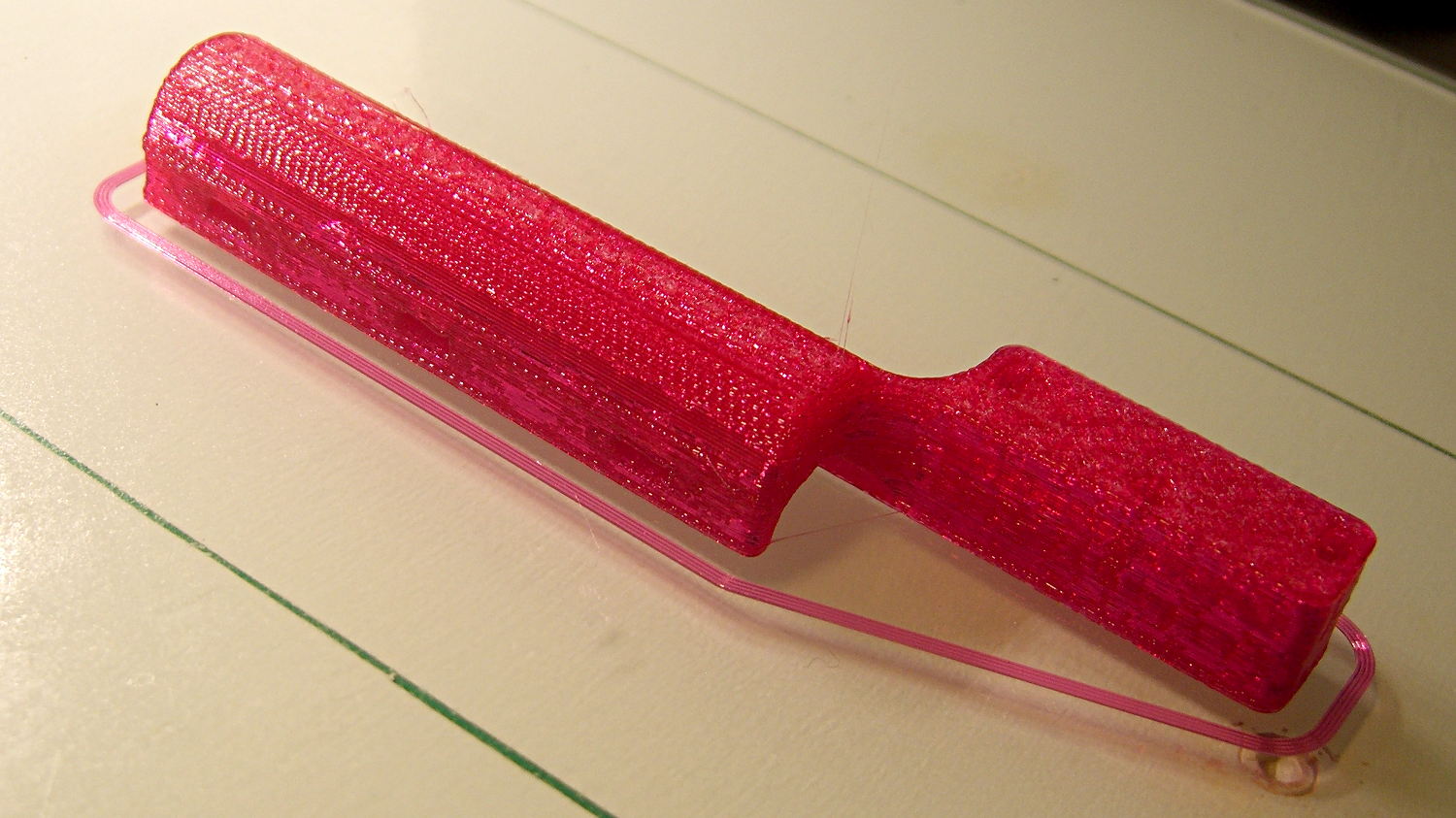
Her wish being my command:
Clover MCI-900 Mini Iron – Angled holder
I’m still not convinced that having the hot end up in the air is a Good Thing, but she thinks it’s worth trying as-is. A pair of 10-32 screw holes under each end will let it mount to a base board, should that becomes necessary.
I’ll stick a foam sheet under the platform so it doesn’t slide around. The cord normally dangles downward off the side of the ironing board or work table, so the iron won’t get up and walk away, but it might pull the whole affair toward the edge.
I should fill the letters with JB Weld epoxy darkened with laser printer toner (who knew?) to make them stand out. They’re more conspicuous in person than in the picture, so maybe it doesn’t matter.
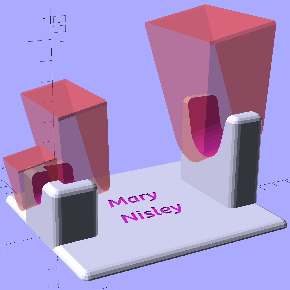
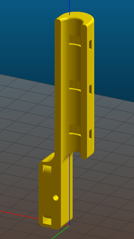
The slots holding the iron have a semicircular bottom and straight-wall sides, created by extruding hulled 2D shapes, arranging them along the iron’s central axis, and tilting the “iron” at the appropriate angle:
Clover Mini Iron Holder – solid model showing iron
That’s a 10° tilt, chosen because it looked right. The model recomputes itself around the key dimensions, so we can raise / lower the iron, change the angle, and so forth and so on, as needed.
Assuming that a hot end sticking out in mid-air isn’t too awful, this one looks like a keeper.
The OpenSCAD source code:
// Clover MCI-900 Mini Iron holder
// Ed Nisley KE4ZNU - August 2015

Layout = "Holder";					// Iron Holder

//- Extrusion parameters - must match reality!

ThreadThick = 0.25;
ThreadWidth = 0.40;

function IntegerMultiple(Size,Unit) = Unit * ceil(Size / Unit);

Protrusion = 0.1;

HoleWindage = 0.2;

inch = 25.4;

Tap10_32 = 0.159 * inch;
Clear10_32 = 0.190 * inch;
Head10_32 = 0.373 * inch;
Head10_32Thick = 0.110 * inch;
Nut10_32Dia = 0.433 * inch;
Nut10_32Thick = 0.130 * inch;
Washer10_32OD = 0.381 * inch;
Washer10_32ID = 0.204 * inch;

//------
// Dimensions

CornerRadius = 4.0;

CenterHeight = 25;							// center at cord inlet on body

BodyLength = 110;							// cord inlet to body curve at front flange

Incline = 10;								// central angle slope

FrontOD = 29;
FrontBlock = [20,1.5*FrontOD + 2*CornerRadius,FrontOD/2 + CenterHeight + BodyLength*sin(Incline)];

CordOD = 10;
CordLen = 10;

RearOD = 22;
RearBlock = [15 + CordLen,1.5*RearOD + 2*CornerRadius,RearOD/2 + CenterHeight];

PlateWidth = 2*FrontBlock[1];

TextDepth = 3*ThreadThick;

ScrewOC = BodyLength - FrontBlock[0]/2;
ScrewDepth = CenterHeight - FrontOD/2 - 5;

echo(str("Screw OC: ",ScrewOC));

BuildSize = [200,250,200];					// largest possible thing

module PolyCyl(Dia,Height,ForceSides=0) {			// based on nophead's polyholes

  Sides = (ForceSides != 0) ? ForceSides : (ceil(Dia) + 2);

  FixDia = Dia / cos(180/Sides);

  cylinder(r=(FixDia + HoleWindage)/2,
           h=Height,
	   $fn=Sides);
}

// Trim bottom from child object

module TrimBottom(BlockSize=BuildSize,Slice=CornerRadius) {

	intersection() {
		translate([0,0,BlockSize[2]/2])
			cube(BlockSize,center=true);
		translate([0,0,-Slice])
			children();
	}
}

// Build a rounded block-like thing

module RoundBlock(Size=[20,25,30],Radius=CornerRadius,Center=false) {

	HS = Size/2 - [Radius,Radius,Radius];
	translate([0,0,Center ? 0 : (HS[2] + Radius)])
	hull() {
		for (i=[-1,1], j=[-1,1], k=[-1,1]) {
			translate([i*HS[0],j*HS[1],k*HS[2]])
				sphere(r=Radius,$fn=4*4);
		}
	}
}

// Create a channel to hold something
// This will eventually be subtracted from a block
// The offsets are specialized for this application...

module Channel(Dia,Length) {

	rotate([0,90,0])
		linear_extrude(height=Length)
			rotate(90)
				hull() {
					for (i=[-1,1])
						translate([i*Dia,2*Dia])
							circle(d=Dia/8);
					circle(d=Dia,$fn=8*4);
				}
}

// Iron-shaped series of channels to be removed from blocks

module IronCutout() {

	union() {
		translate([-2*CordLen,0,0])
			Channel(CordOD,2*CordLen + Protrusion);
		Channel(RearOD,RearBlock[0] + Protrusion);
		translate([BodyLength - FrontBlock[0]/2 - FrontBlock[0],0,0])
			Channel(FrontOD,2*FrontBlock[0]);

	}

}

//- Build it

if (Layout == "Iron")
	IronCutout();

if (Layout == "Holder")
	difference() {
		union() {
			translate([(BodyLength + CordLen)/2 - CordLen,0,0])
				TrimBottom()
					RoundBlock(Size=[(CordLen + BodyLength),PlateWidth,CornerRadius]);

			translate([(RearBlock[0]/2 - CordLen),0,0])
				TrimBottom()
					RoundBlock(Size=RearBlock);

			translate([BodyLength - FrontBlock[0]/2,0,0]) {
				TrimBottom()
					RoundBlock(Size=FrontBlock);
			}
		}

		translate([0,0,CenterHeight])
			rotate([0,-Incline,0])
				IronCutout();

		translate([0,0,-Protrusion])
			PolyCyl(Tap10_32,ScrewDepth + Protrusion,6);

		translate([ScrewOC,0,-Protrusion])
			PolyCyl(Tap10_32,ScrewDepth + Protrusion,6);

		translate([(RearBlock[0] - CordLen) + BodyLength/2 - FrontBlock[0],0,CornerRadius - TextDepth]) {

			translate([0,10,0])
				linear_extrude(height=TextDepth + Protrusion,convexity=1)		// rendering glitches for convexity > 1
					text("Mary",font="Ubuntu:style=Bold Italic",halign="center",valign="center");

			translate([0,-10,0])
				linear_extrude(height=TextDepth + Protrusion,convexity=1)		// rendering glitches for convexity > 1
				text("Nisley",font="Ubuntu:style=Bold Italic",halign="center",valign="center");
		}

	}
The M2 buzzed away for four hours on that puppy, with the first 2½ hours devoted to building the platform. That’s the downside of applying Hilbert Curve infill to two big flat surfaces, but the texture looks really good.
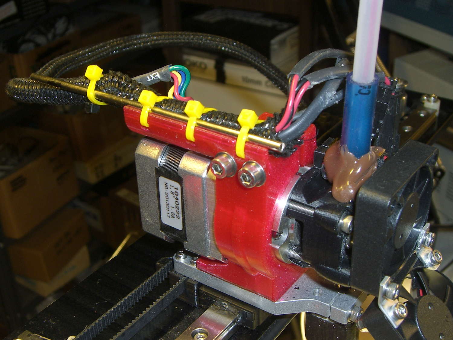
My Sony HDR-AS30V is an action camera, but requires an external case / frame to mount it on anything. Here’s the camera inside its AKA-SF1 Skeleton Frame atop my helmet:
Sony HDR-AS30V camera on bike helmet – inverted
Four 1 mm tall ramps on the inside of the black base (the part just above the yellow sled) snap into 2.6 mm square sockets in the skeleton frame surrounding the camera. For an unknown reason(s) that surely involves applying forces I don’t remember, an opposing pair of those ramps broke off, leaving the other pair to loosely hold one end of the camera in place.
In this picture, the left ramps (one visible) are missing, leaving a square-ish gray scar that’s nearly indistinguishable from the reflection on the intact ramp on the right:
Sony HDR-AS30V Skeleton Mount – broken latch ramps
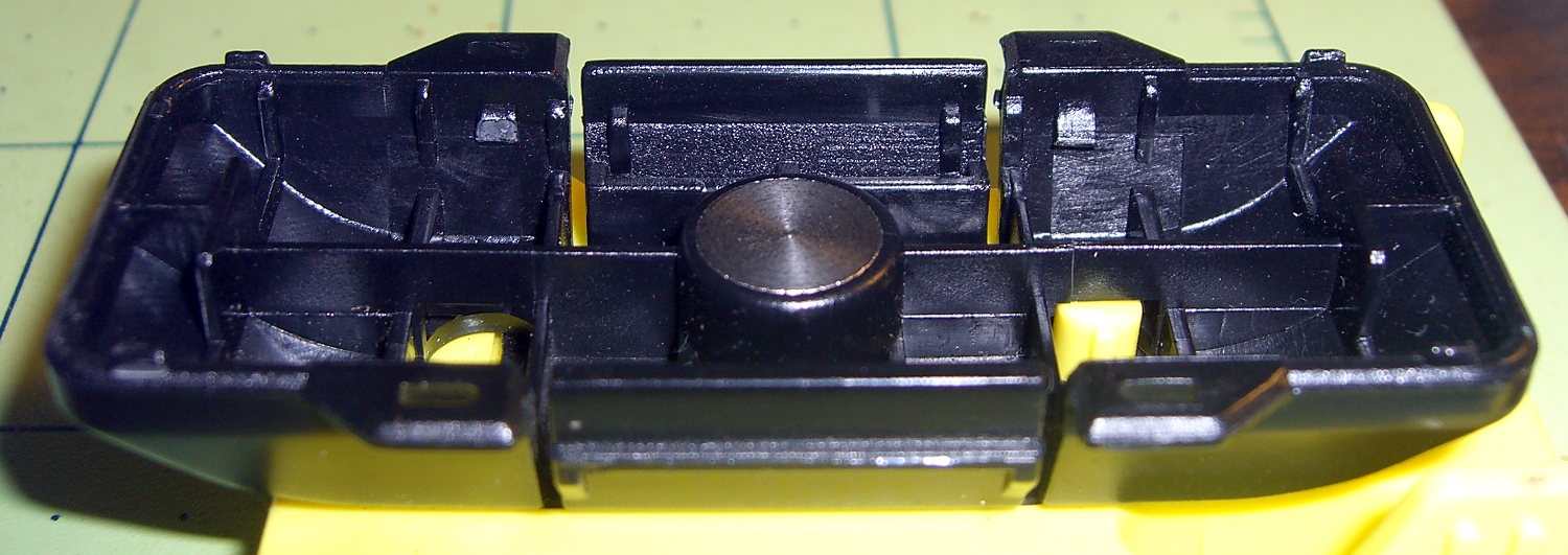
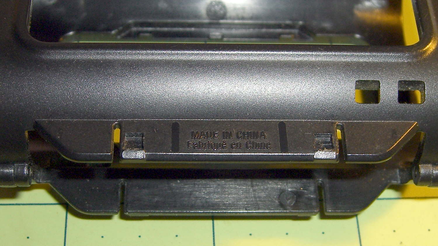
Surprisingly, the round head of a brass 0-80 machine screw fits neatly inside the square socket on the frame; they’re a bit more than 1 mm deep. The approach ramps visible below the sockets guide the latches on the base:
Sony HDR-AS30V Skeleton Mount – frame sockets
So I figured I could just shave off the remaining two latch ramps, drill four holes at the proper spots, and replace the plastic ramps with metal screws.
I clamped the skeleton frame to the Sherline’s tooling plate, aligned it parallel to the X axis, put the laser spot dead center in the square socket, then snapped the base onto the frame. The laser spot shows where the drill will hit:
Sony HDR-AS30V Skeleton Mount – laser hole alignment
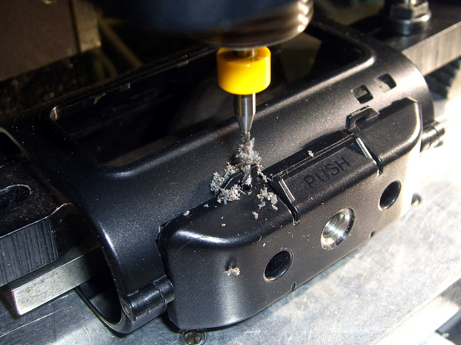
A carbide drill did the honors:
Sony HDR-AS30V Skeleton Mount – 0-80 hole drilling
That’s a #55 = 0.0520 hole for 50% thread, rather than the proper 3/64 = 0.0469 hole for 75% thread, because that’s the closest short carbide drill I had; an ordinary steel twist drill, even in the screw-machine length I use on the Sherline, would probably scamper away. The hole isn’t quite on the sloped bottom edge of the base, but it’s pretty close.
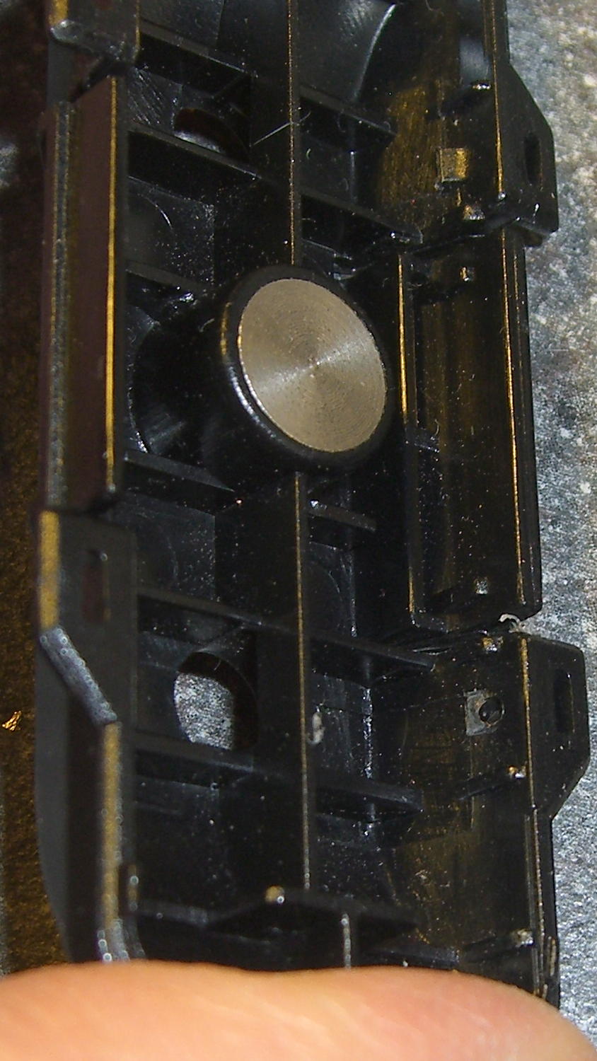
The first hole didn’t emerge quite in the center of its ramp scar:
Sony HDR-AS30V Skeleton Mount – hole position – interior
Which made sense after I thought about it: the ramp tapers to nothing in the direction of the offset, so the hole actually was in the middle of the matching socket.
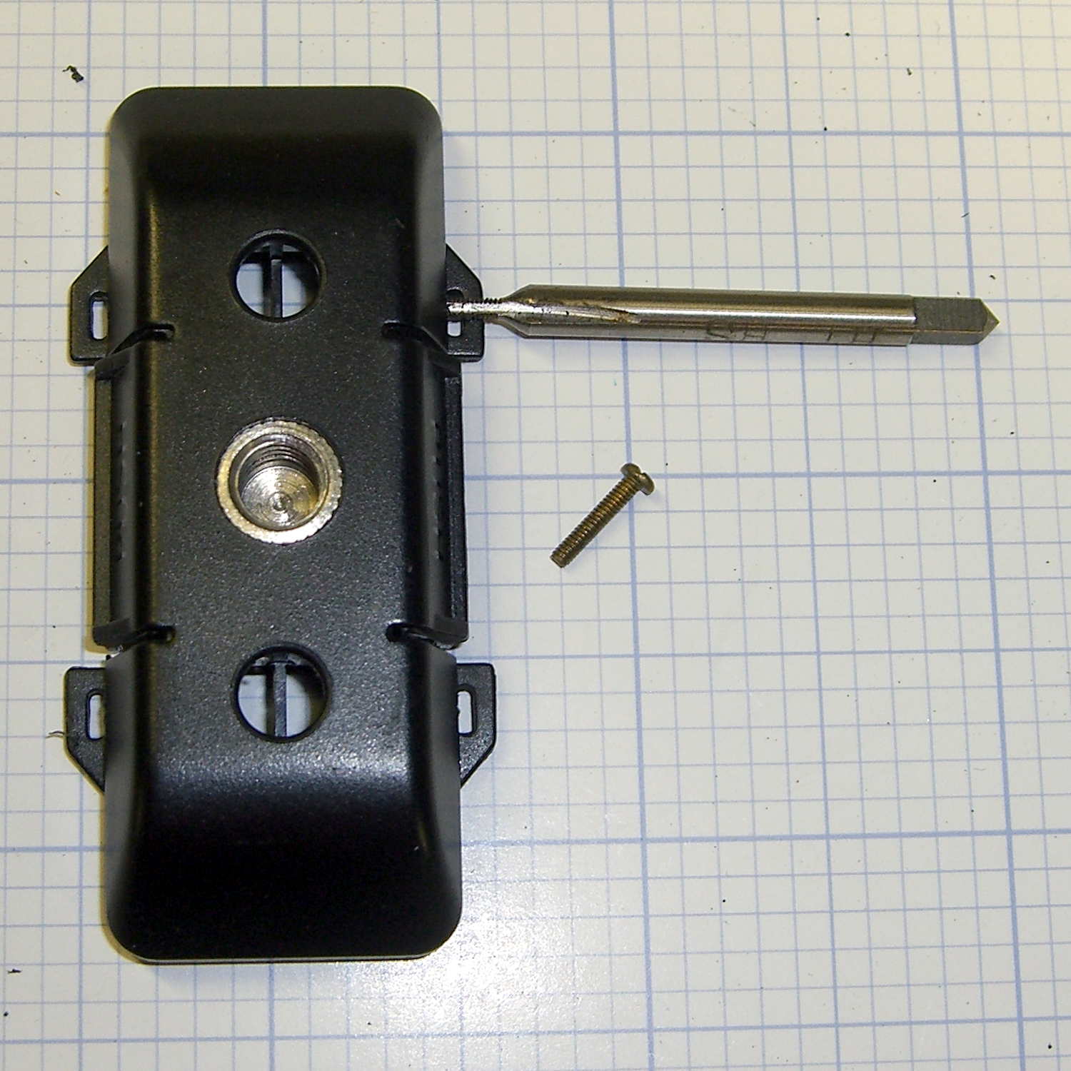
Threading the holes required nothing more than finger-spinning an 0-80 tap:
Sony HDR-AS30V Skeleton Mount – tapping 0-80
The feeble thread engagement didn’t matter, because those mysterious tabs-with-slots (possibly for tie-down strings?) just above the holes were a perfect fit for 0-80 brass nuts:
Sony HDR-AS30V Skeleton Mount – reassembled
The screw heads extend into the sockets, hold the frame solidly in the base, and make it impossible to pull out. Although the frame still slides / snaps into the base, that seems like it will wear out the sockets in fairly short order, so I’ll unlatch the frame (with the yellow slide latch on top), open it up, ease it into position, and then latch it in place. That was the only way to remove it from the original latches, so it’s not a big deal.
I should add a drop of epoxy to each of those nuts and perhaps fill the screw slots with epoxy to keep them from abrading the plastic inside the sockets. Maybe a dab of epoxy on the heads, followed by latching the frame in place, would form four square pegs to exactly fill the sockets.
This was a straightforward repair that should not have been necessary…