Ed Nisley's Blog: Shop notes, electronics, firmware, machinery, 3D printing, laser cuttery, and curiosities. Contents: 100% human thinking, 0% AI slop.
Tag: Improvements
Making the world a better place, one piece at a time
The big bag o’ new-old-stock Inmac ball-point plotter pens had five different colors, so I popped a black ceramic tip pen in Slot 0 and ran off Yet Another Superformula Demo Plot:
HP 7475A – Inmac ball pens – weak blue
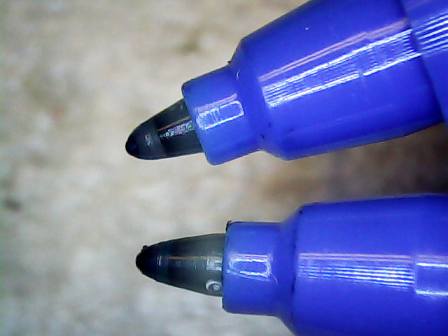
All the ball pens produce spidery lines, but the blue pen seemed intermittent. Another blue pen from the bag behaved the same way, so I pulled the tip outward and tucked a wrap of fine copper wire underneath. You can see the wire peeking out at about 5 o’clock, with the end at 3-ish:
HP 7475A – Inmac ball pen – wire spacer
The wire holds the tip slightly further away from the locating flange and, presumably, makes it press slightly harder against the paper:
HP 7475A – Inmac ball pen – stock vs. extended
A bit more pressure helped, but not enough to make it dependable, particularly during startup on the legend characters:
HP 7475A – Inmac ball pens – extended blue
That black line comes from an ordinary fiber-tip pen that looks like a crayon on a paper towel by comparison with the hair-fine ball point lines.
Delicacy doesn’t count for much in these plots, so I’ll save the ball pens for special occasions. If, that is, I can think of any…
An undrilled double-sided circuit board with the edges bonded together doesn’t look like much:
Electrometer amp – undrilled shield planes
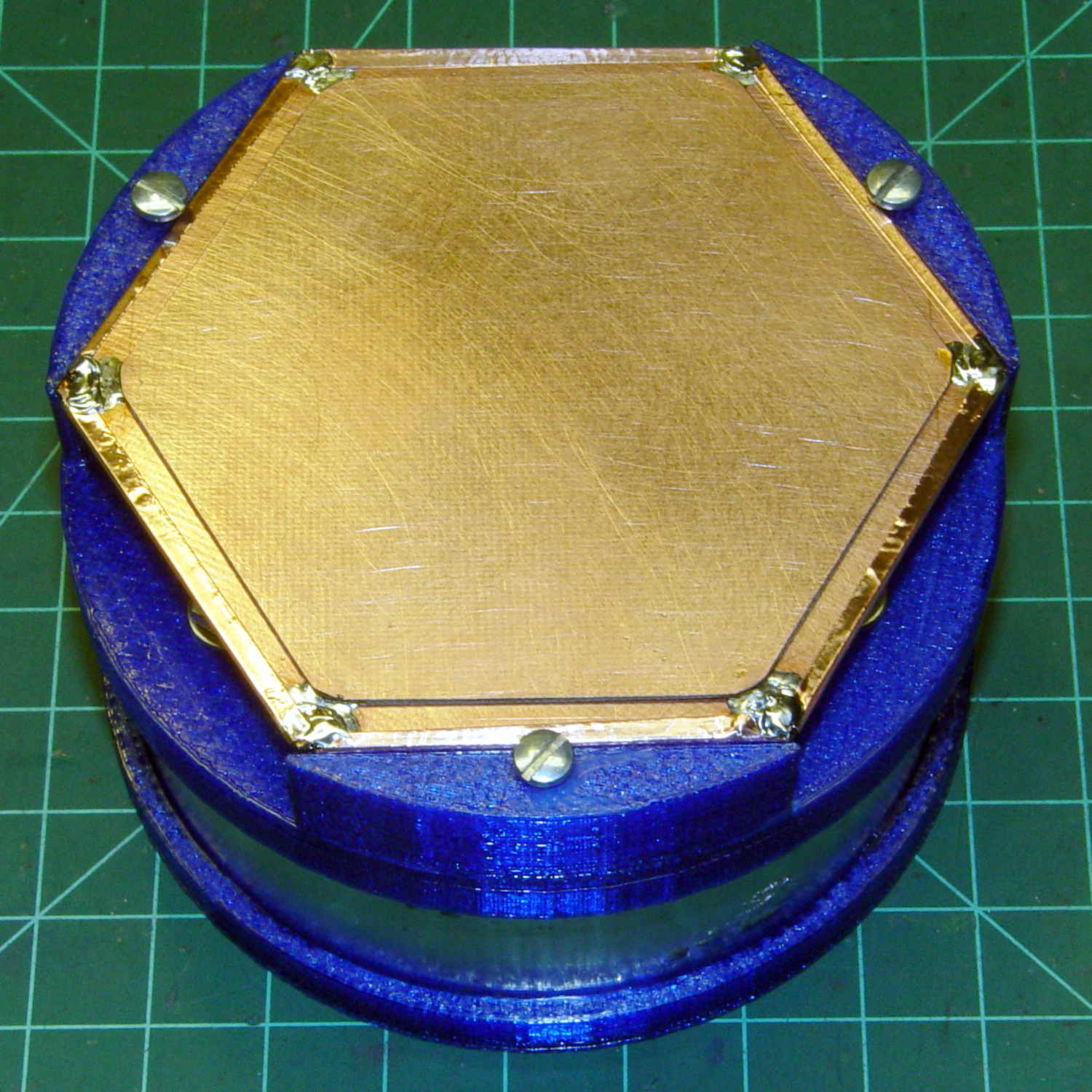
Soldering a smaller hex to the center of the bonded plate produces an isolated plane:
Electrometer amp – finished shield planes
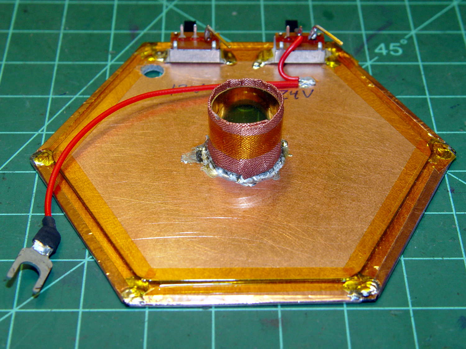
The copper fabric tape wrapped around a brass tube soldered to the isolated plane contacts the ionization chamber shell around the central contact and (should) provide complete shielding. Kapton tape around the edges reduces the likelihood of inadvertent shorts.
Working with a shield at +24 V gave me the shakes, so this one confines the chamber bias to the isolated hex and shell, with the larger hex at circuit common (a.k.a. ground). The isolated plane has about 275 pF to the ground plane, which isn’t a Bad Thing at all. In principle, the chamber bias doesn’t need a switch, because there’s no current drain, but I vastly prefer having cold circuitry before popping the lid.
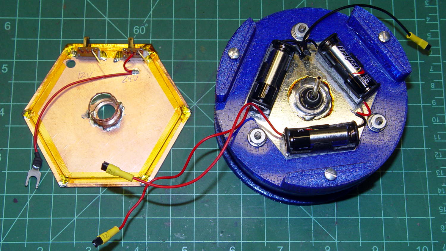
If I had a small DPST switch, I’d use it:
Electrometer amp – chamber – shield planes
As it stands, one switch controls the +24 V chamber bias and the other switches +12 V power to the electrometer amp front end, with simpleminded connectors so I can separate the pieces.
We’ll see how well all that works in practice.
An alert reader will notice the tiny difference between the blue PETG shapes in the two pictures. The bottom one comes from the revised code, of course.
It has a number of shortcomings (notice the padding taped to the corner of the useless drawers), but the most pressing problem was that it didn’t quite line up with the table top in the Basement Sewing Room. After some pondering, we decided to shorten the legs and install leveling screws.
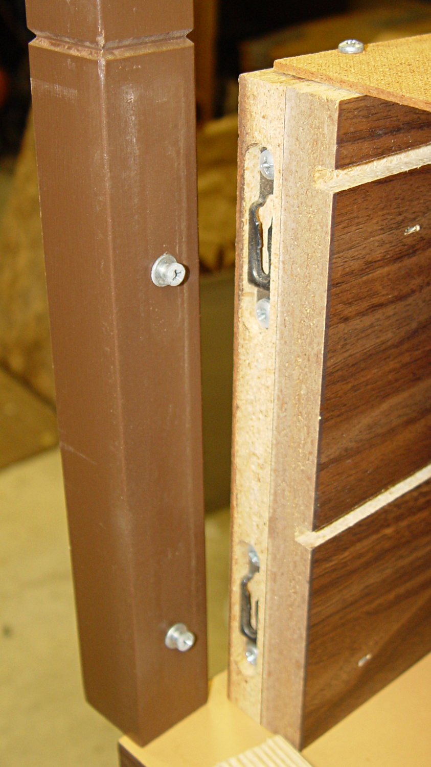
The first problem was figuring out how to dismantle the thing. It turns out the legs have completely hidden joint hardware:
Sears Sewing Table – leg joint hardware
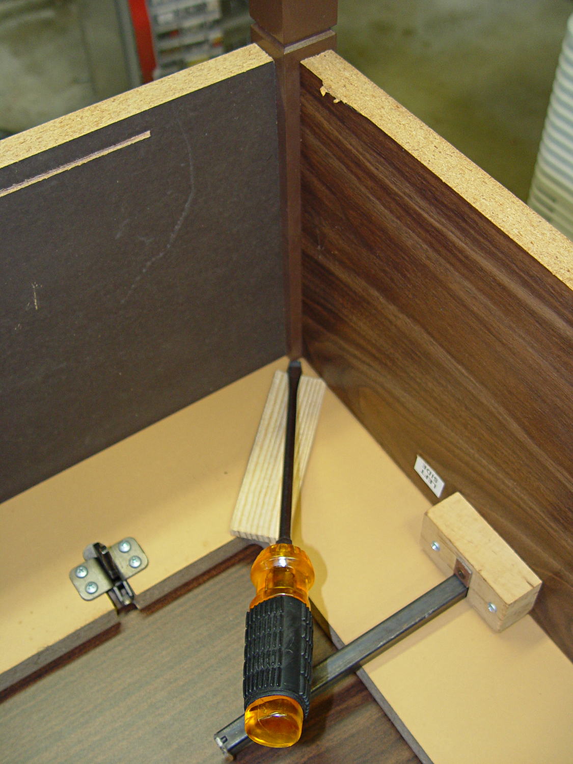
They’re obviously intended as assemble-only fittings, but prying from the inside of the corners will put the tool marks where they can’t be seen:
Sears Sewing Table – leg removal
The legs taper below the fittings and require shims to prevent horrible saw accidents:
Sears Sewing Table – leg shortening
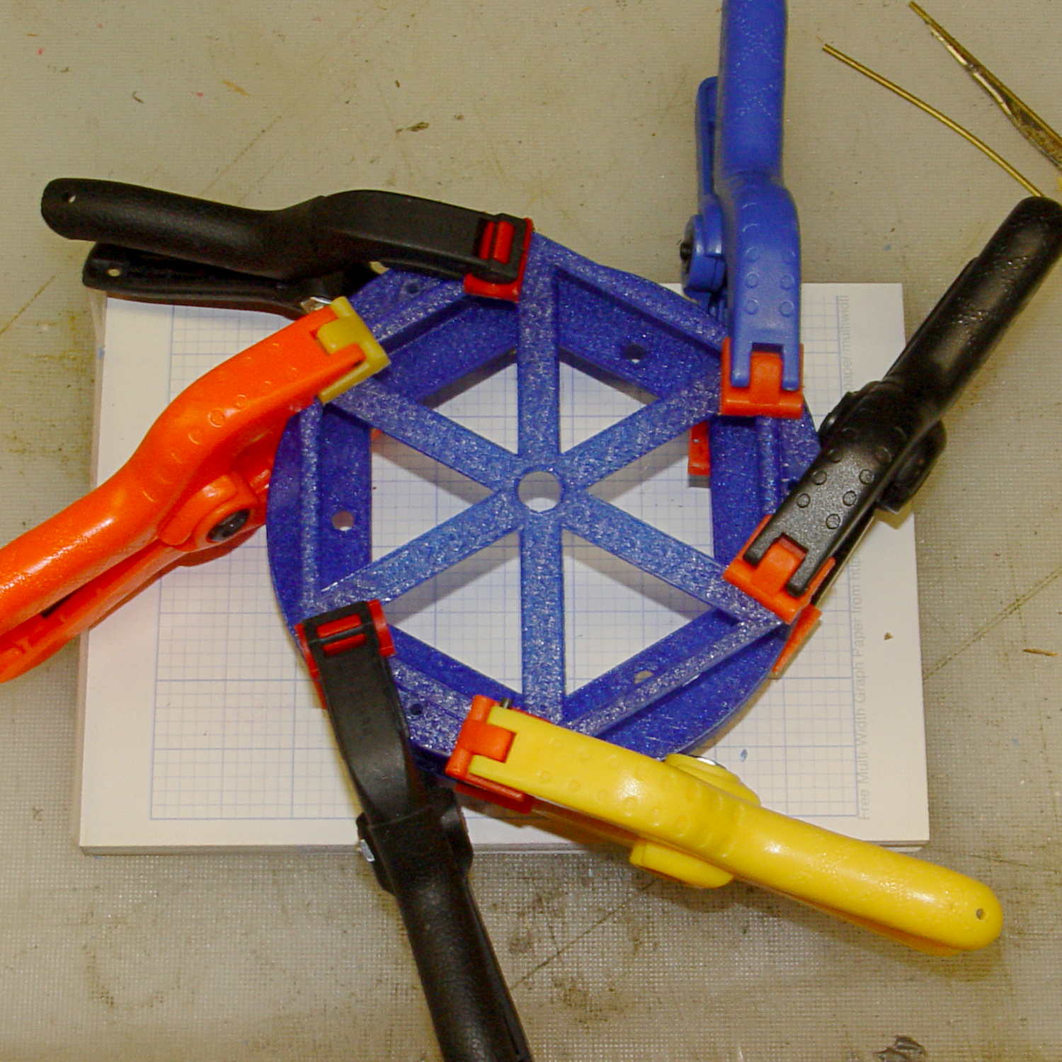
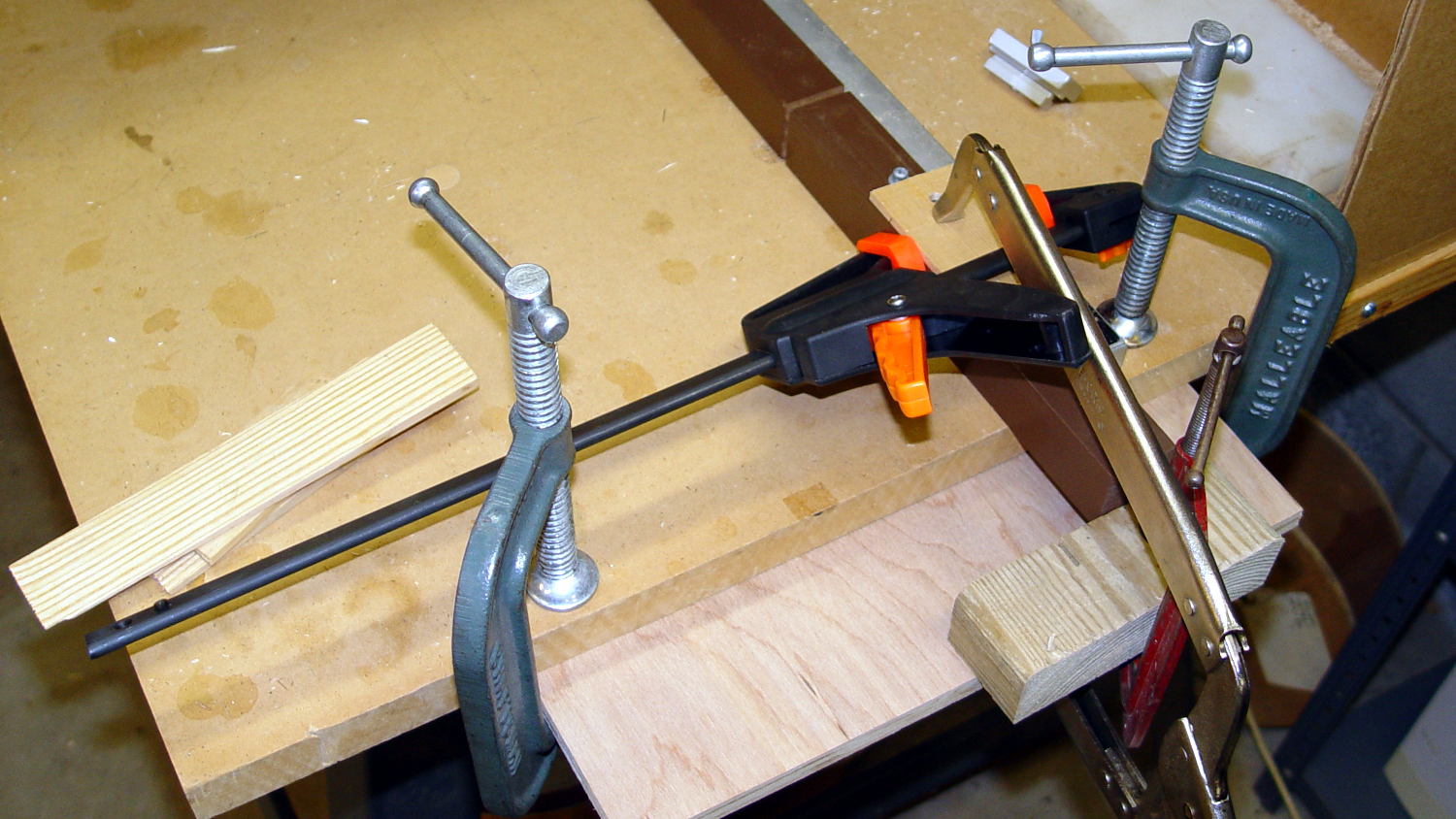
Another in my continuing series of Why You Can Never Have Too Many Clamps shows the square section of the leg aligned with the saw fence:
Sears Sewing Table – leg clamps
And when the cuttin’ were done, it turned out that the table had two different types of legs with (at least) two different lengths:
Sears Sewing Table – leg cutoffs
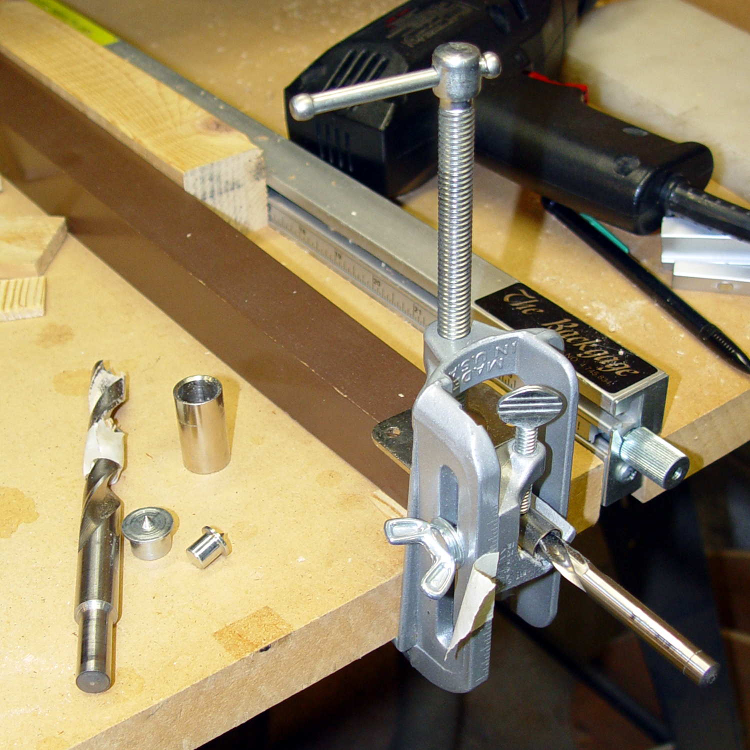
I have a bunch of 5/16 inch feet from some random industrial hardware, so I drilled a 5/16 inch hole into the legs, using a doweling jig and more shims:
Sears Sewing Table – leg drilling setup – overview
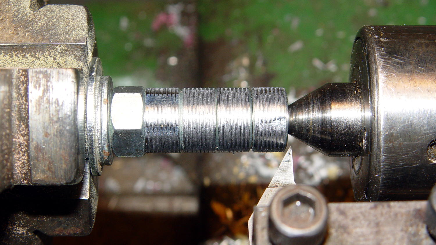
Normally, you’d bang a T-nut into each leg, but I thought those spikes would split the minimal wood remaining around the hole, so I turned the corners off a quartet of ordinary hex nuts and laid a coarse groove along their length:
Sears Sewing Table – preparing nut inserts
The modified nuts are 1/2 inch OD and you should drill that hole before the longer 5/16 inch clearance hole. I’ll eventually dab some epoxy in the holes, seat the nuts, and that’ll be a permanent installation with no risk of cracking the legs.
The snippet of tape on the doweling jig remembers the drill guide position, but the legs were sufficiently different that each one required different shims and some hand-tuning:
Sears Sewing Table – leg drilling setup – detail
I dry-assembled the table in anticipation of more modifications. Basically, you wiggle-jiggle the leg studs into their latches, then whack the end of the leg with a rubber mallet to seat it against the underside of the tabletop.
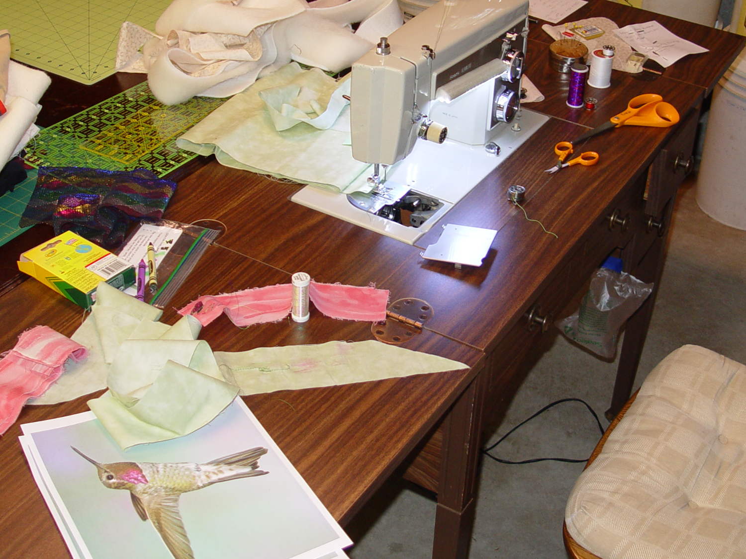
Slicing another half inch off the legs seems like a Good Idea that should better match the upstairs table. Mary also wants to round off the drawers and remove a bit of the front panel, which will require dismantling the entire table, but that can wait for a pause in the quilting.
The 12 in. ratchet bar clamp/spreader is a light duty tool that’s perfect for delicate woodwork or scale modeling.
Yeah, right. (*)
It’s an awkward, clunky, heavy steel bar with chunky plastic fittings, not at all suitable for “delicate woodwork”. In my case, I attempted to clamp a 4×4 block against a bonded pair of of 2×4 studs before drilling a pair of bolt holes, whereupon one of the clamps failed. I deployed a spare clamp (always have a backup) and completed the mission.
An autopsy showed the problem:
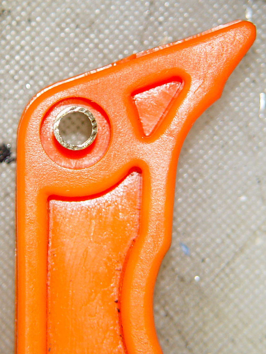
Harbor Freight Bar Clamp – failed handle pivot
The orange handle magnifies the applied force by the (more or less) 4:1 lever arm and applies it against two hollow plastic bosses on the side plates. The one just below the handle broke free, which is exactly what you’d expect to happen.
The through hole looks like it should pass a pivot, but that’s not the case:
Harbor Freight Bar Clamp – handle detail 1
I drilled out the hole just slightly to fit a snippet of brass tubing:
Harbor Freight Bar Clamp – brass bushing
If the tubing looks slightly off-center, that’s because it is. The two halves of the injection mold weren’t aligned, as you can see along the top edge of the picture, putting the hole off-center. The broken boss took most of the reaction force from the handle: a poor bad design compounded by crappy production QC.
I filled the empty spaces with epoxy, topped it off with a pair of washers, match-drilled holes in the side plates, and ran a stainless 8-32 screw through the brass tubing:
Harbor Freight Bar Clamp – reinforced pivot
The end-on view shows the misaligned handle halves:
Harbor Freight Bar Clamp – repaired – edge view
It’s not nearly as stylish, but the handle pivot won’t fail again. I should preemptively repair the other clamps, but …
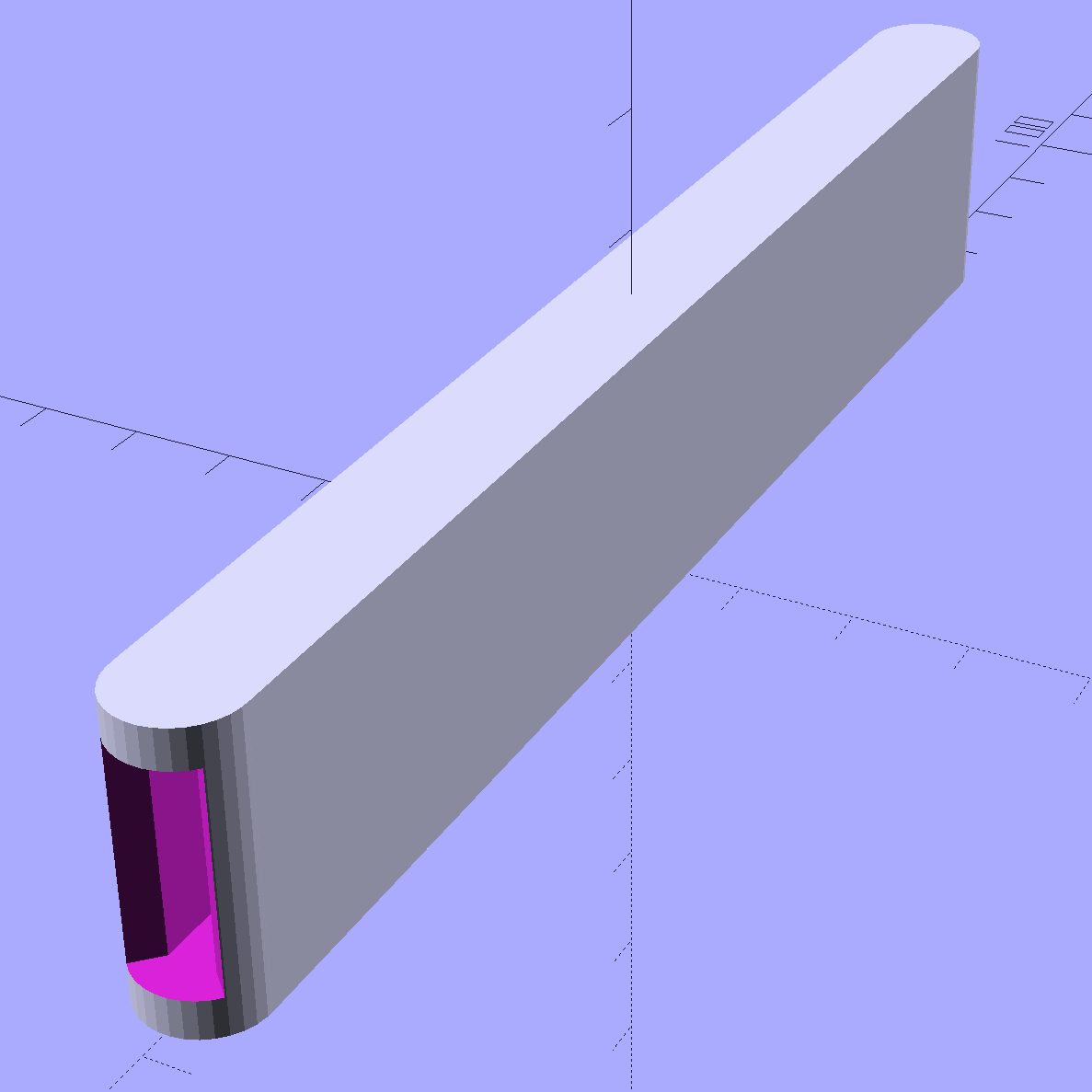
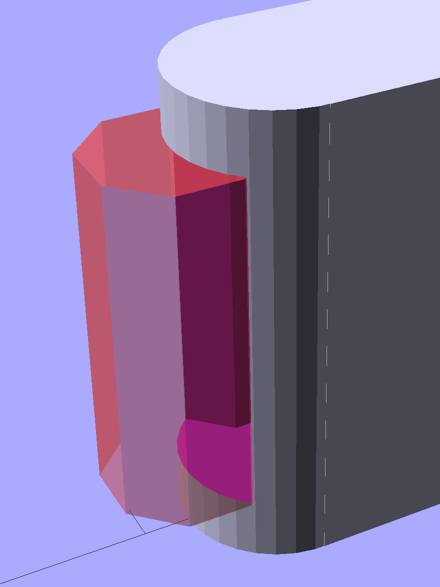
The ends have nice chamfered entrances made from octagons:
Garden Knife Sheath – entrances – solid model
The thing went away so fast I didn’t get a chance to photograph it, but magenta PETG filament should make it much harder to mislay, out there among the greenery…
The OpenSCAD source code:
// Garden Knife Scabbard
// Ed Nisley KE4ZNU - August 2015

//- Extrusion parameters - must match reality!

ThreadThick = 0.25;
ThreadWidth = 0.40;

function IntegerMultiple(Size,Unit) = Unit * ceil(Size / Unit);

Protrusion = 0.1;

HoleWindage = 0.2;

//------
// Dimensions

WallThick = IntegerMultiple(3.0,ThreadWidth);

Blade = [115,1.8,16.0];

Clearance = [10.0,2.0,2.0];

Slot = Blade + Clearance;

Sheath = Slot + [0,2*WallThick,2*WallThick];

//- Build it


translate([0,0,Sheath[2]/2])
    difference() {
        union() {
            for (i=[-1,1])
                translate([i*Sheath[0]/2,0,-Sheath[2]/2])
                    rotate(180/32)
                        cylinder(d=Sheath[1],h=Sheath[2],$fn=32);
            cube(Sheath,center=true);
        }
        cube(Slot + [Slot[0],0,0],center=true);
        for (i=[-1,1])
            translate([i*(Sheath[0]/2 + Sheath[1]/2),0,-Slot[2]/2])
                rotate(180/8)
                    cylinder(d=Sheath[1] - 4*ThreadWidth,h=Slot[2],$fn=8);
    }
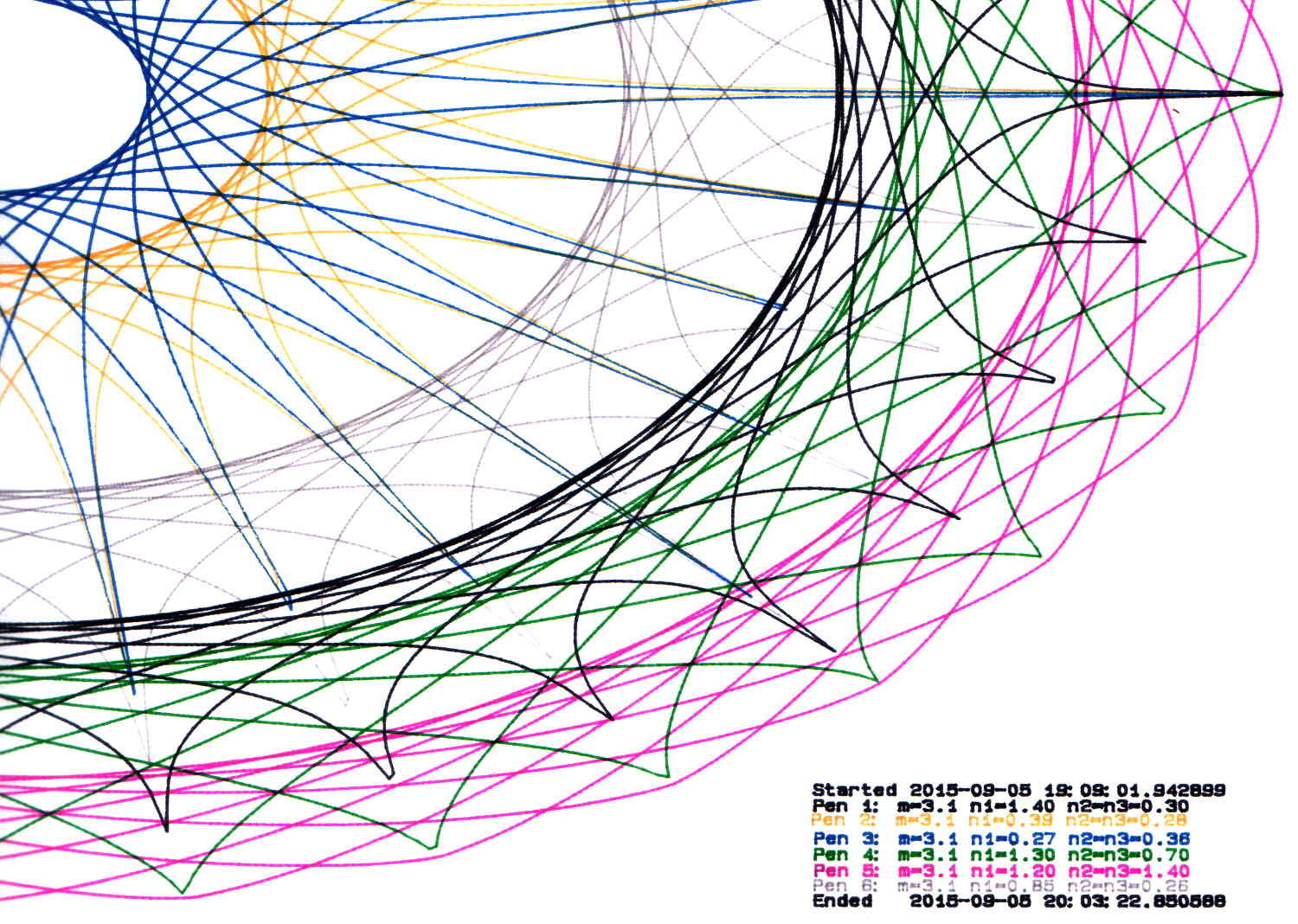
During this plot, an Inmac purple pen (in the Pen 5 slot) pretty much ran out of ink:
HP 7475A – Pen 5 before refill
It printed the legend perfectly and started the trace solidly enough, proceeding upward from the far right, but after ten circuits around the center it returned dragging a very faint line behind it.