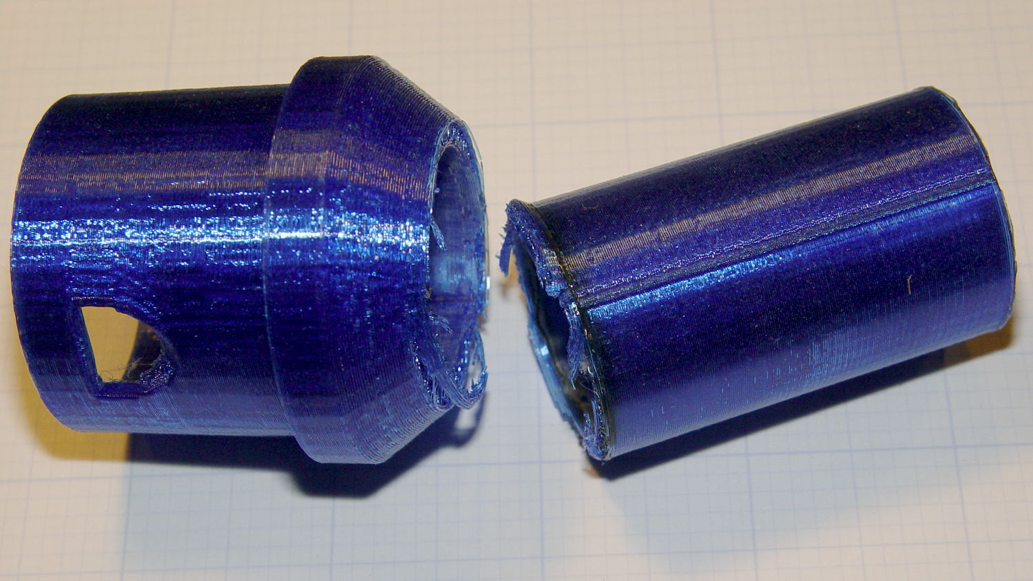
Pretty much as expected, the dust brush nozzle failed again, adjacent to the epoxy repair:
A bit of rummaging turned up some ¾ inch Schedule 40 PVC pipe which, despite the fact that no plumbing measurement corresponds to any physical attribute, had about the right OD to fit inside the adapter’s ID:
The enlarged bore leaves just barely enough space for a few threads around the circumference. Fortunately, the pipe OD is a controlled dimension, because it must fit inside all the molded PVC elbows / tees / caps / whatever.
The pipe ID isn’t a controlled dimension and, given that the walls seemed far too thick for this purpose, I deployed the boring bar:

That’s probably too much sticking out of the chuck, but sissy cuts saved the day. The carriage stop keeps the boring bar 1 mm away from the whirling chuck.
Bandsaw it to length and face the ends:

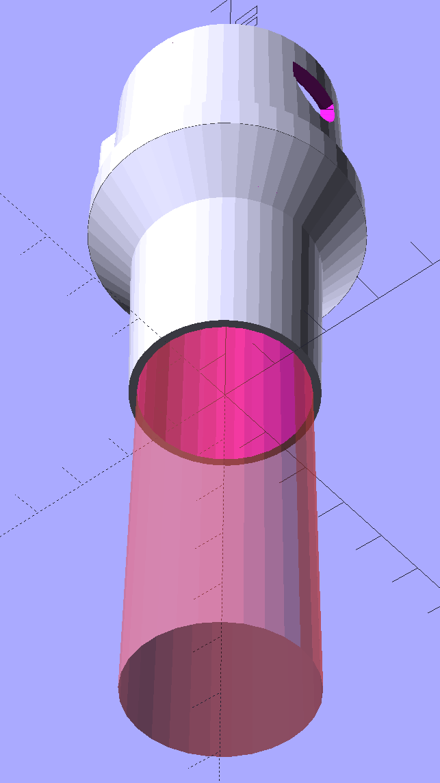
The PVC tube extends from about halfway along the steep taper from the handle fitting out to the end, with the section closest to the handle making the most difference.
Ram it flush with the end:
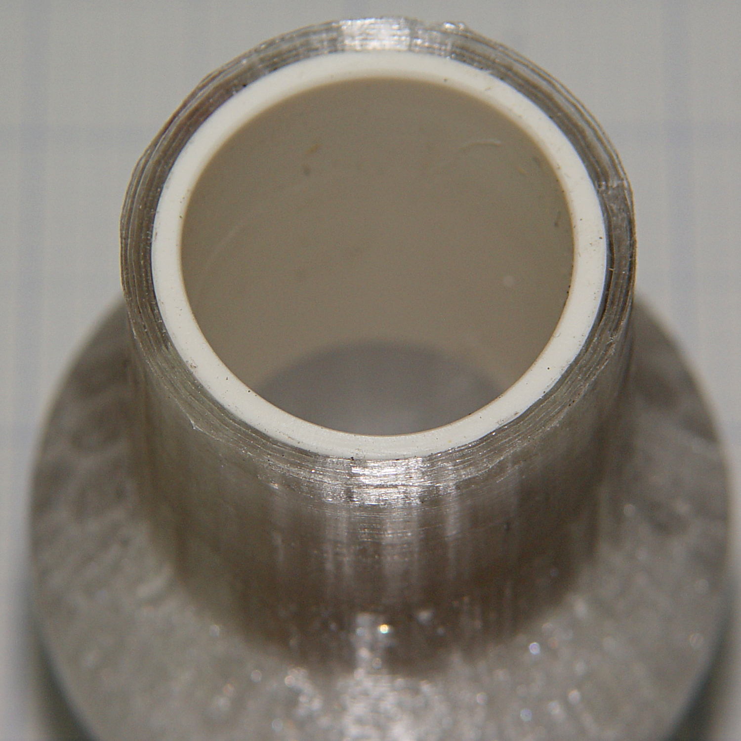
I thought about gluing it in place, but it’s a sufficiently snug press fit that I’m sure it won’t go anywhere.
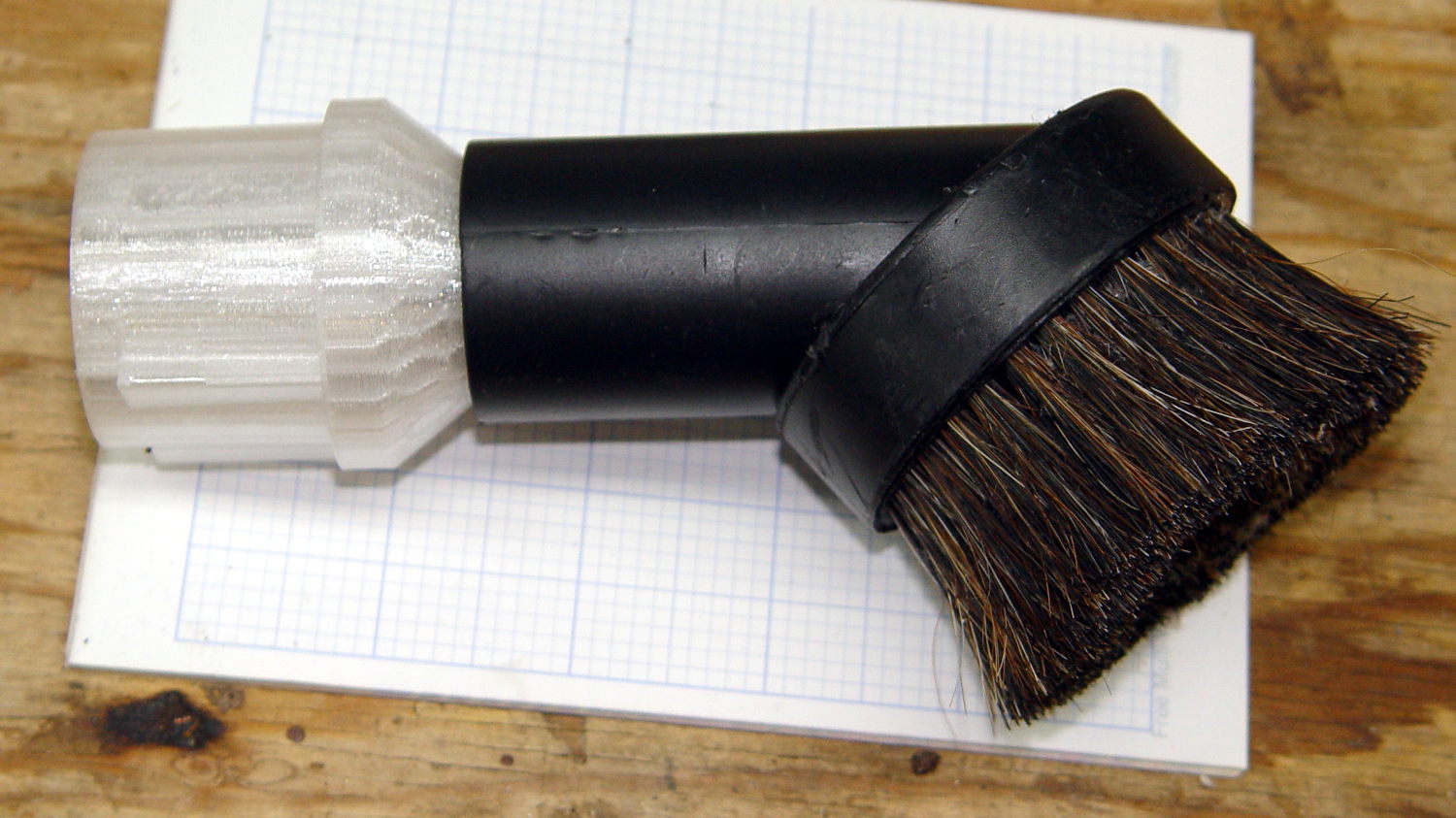
Natural PETG probably isn’t the right color:
Now, let’s see how long that repair lasts …
The OpenSCAD source code as a GitHub Gist:
| //——————- | |
| // eBay horsehair dusting brush | |
| // Hacked for 3/4" Schedule 40 PVC stiffening tube | |
| module DustBrush() { | |
| union() { | |
| translate([0,0,40.0]) | |
| rotate([180,0,0]) | |
| difference() { | |
| union() { | |
| cylinder(d1=EndStop[OD1],d2=31.8,h=10.0); | |
| translate([0,0,10.0 – Protrusion]) | |
| cylinder(d1=32.0,d2=30.0,h=30.0 + Protrusion); | |
| } | |
| translate([0,0,-Protrusion]) | |
| cylinder(d1=26.0,d2=24.0,h=100); | |
| translate([0,0,-Protrusion]) // 3/4 inch Sch 40 PVC | |
| PolyCyl(27.0,100); | |
| } | |
| translate([0,0,40.0 – Protrusion]) | |
| MaleFitting(); | |
| } | |
| } |