The old Atom running LinuxCNC for the Sherline finally stopped booting, so I popped the Optiplex 760 off the stack and did a live-USB trial run. The latency / jitter worked out around 25 µs, slightly worse than before, but still Good Enough, and the StepConf utility coerced the motors into working OK.
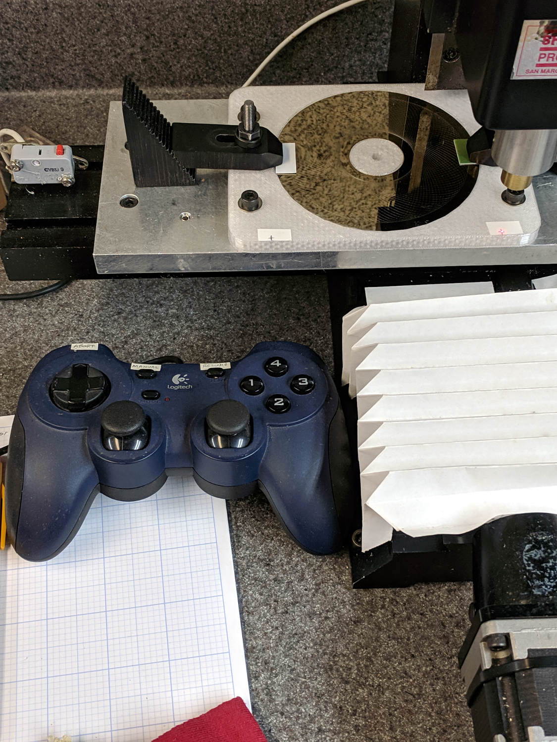
What didn’t work was the old Eagle-to-HAL code defining the Logitch Gamepad as a Joggy Thing to allow smooth joystick jog control. Well, stuff changes over the course of eight years, but, in this case, the fix turned out to be a one-liner: the probe_parport module isn’t needed nowadays.
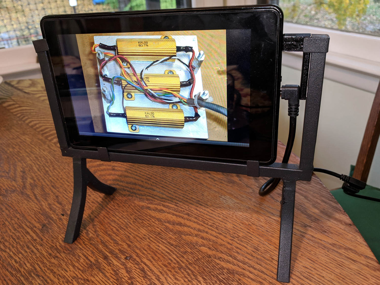
With that out of the way, it runs fine:
The INI and HAL files defining the Sherline configuration as a GitHub Gist:
This file contains hidden or bidirectional Unicode text that may be interpreted or compiled differently than what appears below. To review, open the file in an editor that reveals hidden Unicode characters.
Learn more about bidirectional Unicode characters
| # HAL config file automatically generated by Eagle-CAD ULP: | |
| # [/mnt/bulkdata/Project Files/eagle/ulp/hal-write-2.5.ulp] | |
| # (C) Martin Schoeneck.de 2008 | |
| # Charalampos Alexopoulos 2011 | |
| # Mods Ed Nisley KE4ZNU 2010 2013 | |
| # Path [/mnt/bulkdata/Project Files/eagle/projects/LinuxCNC for M2/] | |
| # ProjectName [LinuxCNC Sherline Configuration] | |
| # File name [/mnt/bulkdata/Project Files/eagle/projects/LinuxCNC for M2/LinuxCNC Sherline Configuration.hal] | |
| # Created [11:17:21 17-Feb-2013] | |
| #################################################### | |
| # Load realtime and userspace modules | |
| loadrt trivkins | |
| loadrt [EMCMOT]EMCMOT key=[EMCMOT]SHMEM_KEY num_joints=[TRAJ]AXES base_period_nsec=[EMCMOT]BASE_PERIOD servo_period_nsec=[EMCMOT]SERVO_PERIOD traj_period_nsec=[EMCMOT]SERVO_PERIOD | |
| # not needed in 2.7 | |
| # loadrt probe_parport | |
| loadrt hal_parport cfg="[PARPORT]ADDRESS out" | |
| loadrt stepgen step_type=0,0,0,0 | |
| loadrt pwmgen output_type=0 | |
| loadusr -W hal_manualtoolchange | |
| loadusr -W hal_input -KA Dual | |
| loadrt logic count=1 personality=0x104 | |
| loadrt constant count=13 | |
| loadrt and2 count=17 | |
| loadrt conv_float_s32 count=1 | |
| loadrt flipflop count=4 | |
| loadrt mux2 count=5 | |
| loadrt mux4 count=1 | |
| loadrt not count=8 | |
| loadrt or2 count=14 | |
| loadrt scale count=7 | |
| loadrt timedelay count=1 | |
| loadrt toggle count=1 | |
| #################################################### | |
| # Hook functions into threads | |
| addf stepgen.make-pulses base-thread | |
| addf pwmgen.make-pulses base-thread | |
| addf parport.0.read base-thread | |
| addf parport.0.write base-thread | |
| addf parport.0.reset base-thread | |
| addf logic.0 base-thread | |
| addf motion-command-handler servo-thread | |
| addf motion-controller servo-thread | |
| addf stepgen.update-freq servo-thread | |
| addf stepgen.capture-position servo-thread | |
| addf pwmgen.update servo-thread | |
| addf constant.0 servo-thread | |
| addf constant.1 servo-thread | |
| addf constant.2 servo-thread | |
| addf constant.3 servo-thread | |
| addf constant.4 servo-thread | |
| addf constant.5 servo-thread | |
| addf constant.6 servo-thread | |
| addf constant.7 servo-thread | |
| addf constant.8 servo-thread | |
| addf constant.9 servo-thread | |
| addf constant.10 servo-thread | |
| addf constant.11 servo-thread | |
| addf constant.12 servo-thread | |
| addf and2.0 servo-thread | |
| addf and2.1 servo-thread | |
| addf and2.2 servo-thread | |
| addf and2.3 servo-thread | |
| addf and2.4 servo-thread | |
| addf and2.5 servo-thread | |
| addf and2.6 servo-thread | |
| addf and2.7 servo-thread | |
| addf and2.8 servo-thread | |
| addf and2.9 servo-thread | |
| addf and2.10 servo-thread | |
| addf and2.11 servo-thread | |
| addf and2.12 servo-thread | |
| addf and2.13 servo-thread | |
| addf and2.14 servo-thread | |
| addf and2.15 servo-thread | |
| addf and2.16 servo-thread | |
| addf conv-float-s32.0 servo-thread | |
| addf toggle.0 servo-thread | |
| addf flipflop.0 servo-thread | |
| addf flipflop.1 servo-thread | |
| addf flipflop.2 servo-thread | |
| addf flipflop.3 servo-thread | |
| addf timedelay.0 servo-thread | |
| addf or2.0 servo-thread | |
| addf or2.1 servo-thread | |
| addf or2.2 servo-thread | |
| addf or2.3 servo-thread | |
| addf or2.4 servo-thread | |
| addf or2.5 servo-thread | |
| addf or2.6 servo-thread | |
| addf or2.7 servo-thread | |
| addf or2.8 servo-thread | |
| addf or2.9 servo-thread | |
| addf or2.10 servo-thread | |
| addf or2.11 servo-thread | |
| addf or2.12 servo-thread | |
| addf or2.13 servo-thread | |
| addf not.0 servo-thread | |
| addf not.1 servo-thread | |
| addf not.2 servo-thread | |
| addf not.3 servo-thread | |
| addf not.4 servo-thread | |
| addf not.5 servo-thread | |
| addf not.6 servo-thread | |
| addf not.7 servo-thread | |
| addf scale.0 servo-thread | |
| addf scale.1 servo-thread | |
| addf scale.2 servo-thread | |
| addf scale.3 servo-thread | |
| addf scale.4 servo-thread | |
| addf scale.5 servo-thread | |
| addf scale.6 servo-thread | |
| addf mux2.0 servo-thread | |
| addf mux4.0 servo-thread | |
| addf mux2.1 servo-thread | |
| addf mux2.2 servo-thread | |
| addf mux2.3 servo-thread | |
| addf mux2.4 servo-thread | |
| #################################################### | |
| # Set parameters | |
| setp parport.0.reset-time [PARPORT]RESET_TIME | |
| setp stepgen.0.maxaccel [AXIS_0]STEPGEN_MAXACCEL | |
| setp stepgen.0.maxvel [AXIS_0]MAX_VELOCITY | |
| setp stepgen.0.dirhold [PARPORT]DIRHOLD | |
| setp stepgen.0.dirsetup [PARPORT]DIRSETUP | |
| setp stepgen.0.steplen [PARPORT]STEPLEN | |
| setp stepgen.0.stepspace [PARPORT]STEPSPACE | |
| setp stepgen.0.position-scale [AXIS_0]SCALE | |
| setp parport.0.pin-03-out-reset FALSE | |
| setp parport.0.pin-05-out-reset FALSE | |
| setp parport.0.pin-07-out-reset FALSE | |
| setp parport.0.pin-09-out-reset FALSE | |
| setp parport.0.pin-17-out-reset FALSE | |
| setp stepgen.1.maxaccel [AXIS_1]STEPGEN_MAXACCEL | |
| setp stepgen.1.maxvel [AXIS_1]MAX_VELOCITY | |
| setp stepgen.1.dirhold [PARPORT]DIRHOLD | |
| setp stepgen.1.dirsetup [PARPORT]DIRSETUP | |
| setp stepgen.1.steplen [PARPORT]STEPLEN | |
| setp stepgen.1.stepspace [PARPORT]STEPSPACE | |
| setp stepgen.1.position-scale [AXIS_1]SCALE | |
| setp stepgen.2.maxaccel [AXIS_2]STEPGEN_MAXACCEL | |
| setp stepgen.2.maxvel [AXIS_2]MAX_VELOCITY | |
| setp stepgen.2.dirhold [PARPORT]DIRHOLD | |
| setp stepgen.2.dirsetup [PARPORT]DIRSETUP | |
| setp stepgen.2.steplen [PARPORT]STEPLEN | |
| setp stepgen.2.stepspace [PARPORT]STEPSPACE | |
| setp stepgen.2.position-scale [AXIS_2]SCALE | |
| setp stepgen.3.maxaccel [AXIS_3]STEPGEN_MAXACCEL | |
| setp stepgen.3.maxvel [AXIS_3]MAX_VELOCITY | |
| setp stepgen.3.dirhold [PARPORT]DIRHOLD | |
| setp stepgen.3.dirsetup [PARPORT]DIRSETUP | |
| setp stepgen.3.steplen [PARPORT]STEPLEN | |
| setp stepgen.3.stepspace [PARPORT]STEPSPACE | |
| setp stepgen.3.position-scale [AXIS_3]SCALE | |
| setp parport.0.pin-04-out-invert TRUE | |
| setp parport.0.pin-06-out-invert TRUE | |
| #################################################### | |
| # Set constants | |
| setp constant.0.value 0.1 | |
| setp constant.1.value 20 | |
| setp constant.2.value [TRAJ]MAX_LINEAR_VELOCITY | |
| setp constant.3.value [TRAJ]MAX_ANGULAR_VELOCITY | |
| setp constant.4.value 60 | |
| setp constant.5.value 0.50 | |
| setp constant.6.value 1.00 | |
| setp constant.7.value 0.10 | |
| setp constant.8.value 0.10 | |
| setp constant.9.value 0.0 | |
| setp constant.10.value -1.0 | |
| setp constant.11.value 0.020 | |
| setp constant.12.value 0.000 | |
| #################################################### | |
| # Connect Modules with nets | |
| net a-amp-enable logic.0.in-03 axis.3.amp-enable-out stepgen.3.enable | |
| net a-analog halui.jog.3.analog mux2.4.out | |
| net a-button-minus or2.0.in0 input.0.btn-joystick and2.7.in0 | |
| net a-button-plus or2.0.in1 input.0.btn-thumb2 and2.8.in0 | |
| net a-buttons-active or2.0.out or2.1.in0 or2.11.in1 | |
| net a-direction parport.0.pin-08-out stepgen.3.dir | |
| net a-disable not.7.out and2.13.in1 | |
| net a-enable or2.11.in0 flipflop.3.out not.7.in mux2.4.sel | |
| net a-jog input.0.abs-z-position mux2.4.in1 | |
| net a-knob-active or2.9.out not.2.in and2.15.in1 | |
| net a-knob-inactive not.2.out and2.14.in1 | |
| net a-select and2.16.in0 and2.15.out | |
| net a-set flipflop.3.set and2.16.out | |
| net a-step parport.0.pin-09-out stepgen.3.step | |
| net all-amps-enabled logic.0.and parport.0.pin-17-out | |
| net angular_motion or2.11.out mux2.0.sel | |
| net any-buttons-active mux4.0.sel0 or2.12.out | |
| net axis-disabled-value constant.9.out mux2.1.in0 mux2.2.in0 mux2.3.in0 mux2.4.in0 | |
| net az-buttons-active or2.1.out or2.12.in1 or2.13.in0 | |
| net az-reset flipflop.2.reset and2.14.out flipflop.3.reset | |
| net button-crawl scale.4.out mux4.0.in3 | |
| net button-fast scale.2.out mux4.0.in1 scale.4.in | |
| net estop-a and2.0.in0 input.0.btn-top2 | |
| net estop-b and2.0.in1 input.0.btn-base | |
| net estop-out parport.0.pin-01-out iocontrol.0.emc-enable-in iocontrol.0.user-enable-out | |
| net homeswitches parport.0.pin-10-in-not axis.0.home-sw-in axis.1.home-sw-in axis.2.home-sw-in axis.3.home-sw-in | |
| net jog-crawl toggle.0.out mux4.0.sel1 | |
| net jog-speed halui.jog-speed mux4.0.out | |
| net knob-crawl mux4.0.in2 scale.3.out | |
| net knob-fast mux4.0.in0 scale.1.out scale.3.in | |
| net manual-mode halui.mode.manual input.0.btn-base3 | |
| net n_9 axis.0.motor-pos-cmd stepgen.0.position-cmd | |
| net n_11 axis.0.motor-pos-fb stepgen.0.position-fb | |
| net n_13 and2.0.out halui.estop.activate | |
| net n_14 or2.3.in0 input.0.btn-base5 | |
| net n_15 or2.3.in1 input.0.btn-base6 | |
| net n_16 toggle.0.in or2.3.out | |
| net n_17 conv-float-s32.0.out input.0.abs-x-flat input.0.abs-y-flat input.0.abs-z-flat input.0.abs-rz-flat | |
| net n_18 constant.1.out conv-float-s32.0.in | |
| net n_19 constant.4.out scale.0.gain | |
| net n_20 constant.5.out scale.1.gain | |
| net n_21 constant.6.out scale.2.gain | |
| net n_22 constant.7.out scale.3.gain | |
| net n_23 scale.4.gain constant.8.out | |
| net n_24 constant.0.out halui.jog-deadband | |
| net n_25 constant.2.out mux2.0.in0 | |
| net n_26 mux2.0.in1 constant.3.out | |
| net n_34 axis.1.motor-pos-cmd stepgen.1.position-cmd | |
| net n_36 axis.1.motor-pos-fb stepgen.1.position-fb | |
| net n_42 or2.7.in0 input.0.abs-x-is-pos | |
| net n_43 or2.7.in1 input.0.abs-x-is-neg | |
| net n_44 or2.8.in0 input.0.abs-y-is-pos | |
| net n_45 or2.8.in1 input.0.abs-y-is-neg | |
| net n_46 or2.9.in0 input.0.abs-z-is-pos | |
| net n_47 or2.9.in1 input.0.abs-z-is-neg | |
| net n_48 or2.10.in0 input.0.abs-rz-is-pos | |
| net n_49 or2.10.in1 input.0.abs-rz-is-neg | |
| net n_51 constant.10.out scale.5.gain scale.6.gain | |
| net n_54 constant.11.out timedelay.0.on-delay | |
| net n_55 constant.12.out timedelay.0.off-delay | |
| net n_56 timedelay.0.out and2.1.in1 and2.2.in1 and2.4.in1 and2.3.in1 and2.5.in1 and2.6.in1 and2.8.in1 and2.7.in1 | |
| net n_57 and2.1.out halui.jog.0.minus | |
| net n_58 and2.2.out halui.jog.0.plus | |
| net n_59 and2.3.out halui.jog.1.minus | |
| net n_60 halui.jog.1.plus and2.4.out | |
| net n_61 and2.5.out halui.jog.2.minus | |
| net n_62 and2.6.out halui.jog.2.plus | |
| net n_63 and2.7.out halui.jog.3.minus | |
| net n_64 and2.8.out halui.jog.3.plus | |
| net n_67 axis.2.motor-pos-cmd stepgen.2.position-cmd | |
| net n_69 axis.2.motor-pos-fb stepgen.2.position-fb | |
| net n_77 axis.3.motor-pos-cmd stepgen.3.position-cmd | |
| net n_79 axis.3.motor-pos-fb stepgen.3.position-fb | |
| net probe-in parport.0.pin-15-in-not motion.probe-input | |
| net program-resume halui.program.resume input.0.btn-base4 | |
| net reset-estop input.0.btn-base2 halui.estop.reset | |
| net tool-change iocontrol.0.tool-change hal_manualtoolchange.change | |
| net tool-changed hal_manualtoolchange.changed iocontrol.0.tool-changed | |
| net tool-number iocontrol.0.tool-prep-number hal_manualtoolchange.number | |
| net tool-prepare-loopback iocontrol.0.tool-prepare iocontrol.0.tool-prepared | |
| net vel-per-minute scale.0.out scale.1.in scale.2.in | |
| net vel-per-second mux2.0.out scale.0.in | |
| net x-amp-enable logic.0.in-00 axis.0.amp-enable-out stepgen.0.enable | |
| net x-analog mux2.1.out halui.jog.0.analog | |
| net x-buttons-active or2.5.in0 or2.4.out | |
| net x-direction parport.0.pin-02-out stepgen.0.dir | |
| net x-disable not.4.out and2.12.in1 | |
| net x-enable not.4.in flipflop.0.out mux2.1.sel | |
| net x-hat-minus or2.4.in1 input.0.abs-hat0x-is-neg and2.1.in0 | |
| net x-hat-plus or2.4.in0 input.0.abs-hat0x-is-pos and2.2.in0 | |
| net x-jog input.0.abs-x-position mux2.1.in1 | |
| net x-knob-active or2.7.out not.0.in and2.9.in0 | |
| net x-knob-inactive not.0.out and2.10.in0 and2.11.in0 | |
| net x-set and2.9.out flipflop.0.set | |
| net x-step parport.0.pin-03-out stepgen.0.step | |
| net xy-buttons-active or2.5.out or2.12.in0 or2.13.in1 | |
| net xy-reset flipflop.0.reset and2.10.out flipflop.1.reset | |
| net xyza-buttons-active or2.13.out timedelay.0.in | |
| net y-amp-enable logic.0.in-01 axis.1.amp-enable-out stepgen.1.enable | |
| net y-analog halui.jog.1.analog mux2.2.out | |
| net y-buttons-active or2.6.out or2.5.in1 | |
| net y-direction parport.0.pin-04-out stepgen.1.dir | |
| net y-disable not.5.out and2.9.in1 | |
| net y-enable flipflop.1.out not.5.in mux2.2.sel | |
| net y-hat-minus or2.6.in1 input.0.abs-hat0y-is-neg and2.4.in0 | |
| net y-hat-plus or2.6.in0 input.0.abs-hat0y-is-pos and2.3.in0 | |
| net y-jog input.0.abs-y-position scale.5.in | |
| net y-jog-reversed mux2.2.in1 scale.5.out | |
| net y-knob-active not.1.in or2.8.out and2.11.in1 | |
| net y-knob-inactive not.1.out and2.10.in1 | |
| net y-select and2.12.in0 and2.11.out | |
| net y-set flipflop.1.set and2.12.out | |
| net y-step parport.0.pin-05-out stepgen.1.step | |
| net z-amp-enable logic.0.in-02 axis.2.amp-enable-out stepgen.2.enable | |
| net z-analog mux2.3.out halui.jog.2.analog | |
| net z-button-minus or2.2.in0 input.0.btn-thumb and2.5.in0 | |
| net z-button-plus or2.2.in1 input.0.btn-top and2.6.in0 | |
| net z-buttons-active or2.2.out or2.1.in1 | |
| net z-direction parport.0.pin-06-out stepgen.2.dir | |
| net z-disable not.6.out and2.16.in1 | |
| net z-enable not.6.in flipflop.2.out mux2.3.sel | |
| net z-jog input.0.abs-rz-position scale.6.in | |
| net z-jog-reversed scale.6.out mux2.3.in1 | |
| net z-knob-active not.3.in or2.10.out and2.13.in0 | |
| net z-knob-inactive not.3.out and2.15.in0 and2.14.in0 | |
| net z-set and2.13.out flipflop.2.set | |
| net z-step parport.0.pin-07-out stepgen.2.step |
This file contains hidden or bidirectional Unicode text that may be interpreted or compiled differently than what appears below. To review, open the file in an editor that reveals hidden Unicode characters.
Learn more about bidirectional Unicode characters
| # Ed Nisley – KE4ZNU | |
| # Just do not run stepconf ever again… | |
| [EMC] | |
| MACHINE = Sherline-XYZA | |
| DEBUG = 0 | |
| RS274NGC_STARTUP_CODE = G21 G40 G49 G54 G80 G90 G92.1 G94 G97 G98 | |
| [DISPLAY] | |
| DISPLAY = axis | |
| EDITOR = gedit | |
| GEOMETRY = AXYZ | |
| POSITION_OFFSET = RELATIVE | |
| POSITION_FEEDBACK = ACTUAL | |
| MAX_FEED_OVERRIDE = 3.0 | |
| INTRO_GRAPHIC = /home/ed/linuxcnc/configs/Sherline-XYZA/Sherline.gif | |
| INTRO_TIME = 3 | |
| PROGRAM_PREFIX = /mnt/bulkdata/ | |
| #PROGRAM_PREFIX = /home/ed/linuxcnc/nc_files/ | |
| #INCREMENTS = .1in .05in .01in .005in .001in .0005in .0001in | |
| INCREMENTS = 10 mm, 1 mm, 0.1 mm, 90 deg, 45 deg, 10 deg | |
| [FILTER] | |
| PROGRAM_EXTENSION = .py Python Script | |
| py = python | |
| [TASK] | |
| TASK = milltask | |
| CYCLE_TIME = 0.010 | |
| [RS274NGC] | |
| PARAMETER_FILE = emc.var | |
| [EMCMOT] | |
| EMCMOT = motmod | |
| SHMEM_KEY = 111 | |
| COMM_TIMEOUT = 1.0 | |
| COMM_WAIT = 0.010 | |
| BASE_PERIOD = 50000 | |
| SERVO_PERIOD = 1000000 | |
| [PARPORT] | |
| ADDRESS = 0x378 | |
| RESET_TIME = 10000 | |
| STEPLEN = 25000 | |
| STEPSPACE = 25000 | |
| DIRSETUP = 50000 | |
| DIRHOLD = 50000 | |
| [HAL] | |
| HALUI = halui | |
| HALFILE = Sherline.hal | |
| HALFILE = custom.hal | |
| POSTGUI_HALFILE = custom_postgui.hal | |
| [TRAJ] | |
| AXES = 4 | |
| COORDINATES = X Y Z A | |
| MAX_ANGULAR_VELOCITY = 45.00 | |
| DEFAULT_ANGULAR_VELOCITY = 36.0 | |
| LINEAR_UNITS = inch | |
| ANGULAR_UNITS = degree | |
| CYCLE_TIME = 0.010 | |
| DEFAULT_VELOCITY = 0.400 | |
| MAX_LINEAR_VELOCITY = 0.400 | |
| POSITION_FILE = lastposition.txt | |
| NO_FORCE_HOMING = 1 | |
| [EMCIO] | |
| EMCIO = io | |
| CYCLE_TIME = 0.100 | |
| TOOL_TABLE = Sherline.tbl | |
| TOOL_CHANGE_AT_G30 = 1 | |
| [AXIS_0] | |
| TYPE = LINEAR | |
| MAX_VELOCITY = 0.400 | |
| MAX_ACCELERATION = 5.0 | |
| STEPGEN_MAXACCEL = 10.0 | |
| SCALE = 16000.0 | |
| FERROR = 0.05 | |
| MIN_FERROR = 0.01 | |
| MIN_LIMIT = -1.0 | |
| MAX_LIMIT = 9.5 | |
| BACKLASH = 0.003 | |
| HOME_IS_SHARED = 1 | |
| HOME_SEQUENCE = 1 | |
| HOME_SEARCH_VEL = 0.3 | |
| HOME_LATCH_VEL = 0.03 | |
| HOME_FINAL_VEL = 0.4 | |
| HOME_OFFSET = 9.1 | |
| HOME = 5.25 | |
| [AXIS_1] | |
| TYPE = LINEAR | |
| MAX_VELOCITY = 0.400 | |
| MAX_ACCELERATION = 5.0 | |
| STEPGEN_MAXACCEL = 10.0 | |
| SCALE = 16000.0 | |
| FERROR = 0.05 | |
| MIN_FERROR = 0.01 | |
| MIN_LIMIT = 0.00 | |
| MAX_LIMIT = 5.10 | |
| BACKLASH = 0.003 | |
| HOME_IS_SHARED = 1 | |
| HOME_SEQUENCE = 2 | |
| HOME_SEARCH_VEL = 0.3 | |
| HOME_LATCH_VEL = 0.03 | |
| HOME_FINAL_VEL = 0.4 | |
| HOME_OFFSET = 5.1 | |
| HOME = 4.5 | |
| [AXIS_2] | |
| TYPE = LINEAR | |
| MAX_VELOCITY = 0.333 | |
| MAX_ACCELERATION = 3.0 | |
| STEPGEN_MAXACCEL = 6.0 | |
| SCALE = 16000.0 | |
| FERROR = 0.05 | |
| MIN_FERROR = 0.01 | |
| MIN_LIMIT = 0.0 | |
| MAX_LIMIT = 6.680 | |
| BACKLASH = 0.005 | |
| HOME_IS_SHARED = 1 | |
| HOME_SEQUENCE = 0 | |
| HOME_SEARCH_VEL = 0.150 | |
| HOME_LATCH_VEL = 0.015 | |
| HOME_FINAL_VEL = 0.33 | |
| HOME_OFFSET = 6.680 | |
| HOME = 6.500 | |
| [AXIS_3] | |
| TYPE = ANGULAR | |
| ###WRAPPED_ROTARY = 1 | |
| MAX_VELOCITY = 40.0 | |
| MAX_ACCELERATION = 250.0 | |
| STEPGEN_MAXACCEL = 275.0 | |
| SCALE = 160.0 | |
| FERROR = 1 | |
| MIN_FERROR = .25 | |
| MIN_LIMIT = -999999999.9 | |
| MAX_LIMIT = 999999999.9 | |
| HOME_SEARCH_VEL = 0 | |
| HOME_LATCH_VEL = 0 | |
| HOME = 0.0 | |