Ed Nisley's Blog: Shop notes, electronics, firmware, machinery, 3D printing, laser cuttery, and curiosities. Contents: 100% human thinking, 0% AI slop.
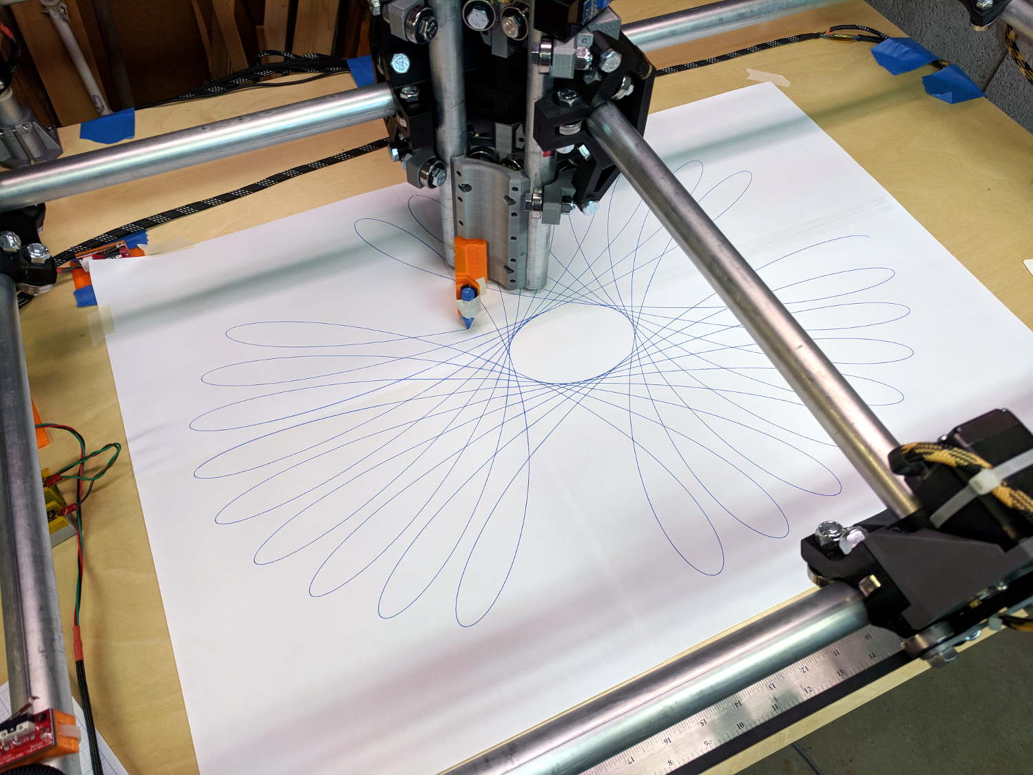
The MPCNC instructions recommend running it for a while, taking it apart, then putting it back together, so all the parts have a chance to relax and get used to working together. To that end, I figured doing some full platform plots would run the rollers over the entire length of the rails:
MPCNC – Full-platform Spirograph – first pass
I taped three B-size sheets together, with an A-size sheet in the far right corner, into a 29×19 inch sheet to put borders around the MPCNC’s 28×18 inch work area. The tape is on the top surface to prevent embarrassing accidents where the pen snags on an edge, at the cost of blurry lines where the ink doesn’t stick quite right.
The far left corner of the paper washes up on the tool length probe’s base, but the pen position turns out to be so repeatable (it should be!) you can swap them with gleeful abandon and get good results:
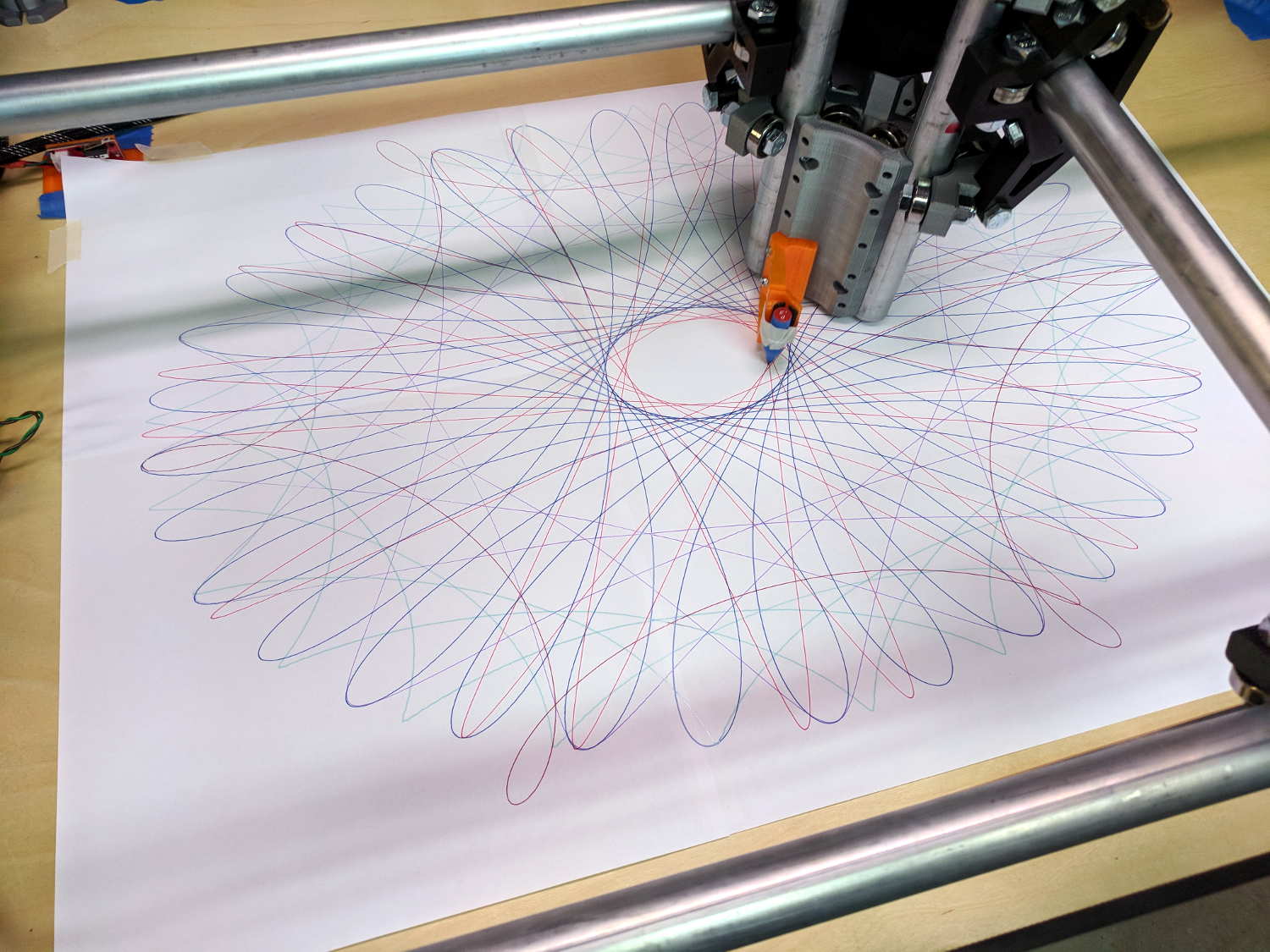
MPCNC – Full-platform Spirograph – multicolor
The pen rumbles along at 12000 mm/min = 200 mm/s = 7.8 inch/s with no hint of wobblulation. Most likely, those big loops aren’t particularly challenging, although watching the big central assembly whip around a tight curve can be startling.
I modified the pen holder for 3-point support, as the recess for the pen flange isn’t quite deep enough:
MPCNC – Pen holder – 3 point grip
Good old masking tape holds the pens securely enough for now.
The glass plate I’d been using for B-size plots doesn’t cover the full area, but I’d set the Z axis limit switch to trip just before the bottom of the rails whacked into the glass. Extending the travel by 5 mm required a snippet of black tape:
MPCNC – Z axis switch – table limit
The patterns come from a scratch-built Spirograph generator, because I wanted to review what’s new in GCMC. More on the software tomorrow …
GCMC includes cycloids.gcmc, a test program producing a fixed set of hypotrochoids and epitrochoids, more commonly known as Spirograph patterns:
GGMC Cycloids test patterns
I’m using them to get familiar with bCNC’s Workspace Coordinate System settings and to exercise the MPCNC hardware; ya gotta plot before you can cut.
Most came out fine, but some showed distinct wobbles:
MPCNC – Cycloid wobble – star
Tight curves and higher speeds produce more wobbles:
MPCNC – Cycloid wobble – loops
You’d probably never feed a wood router over 6000 mm/min = 240 inch/min, so this isn’t as much of a problem as it might appear. Also, I expect a few pounds of router will have fewer wobbulations than a weightless pen hung on a thin plastic mount:
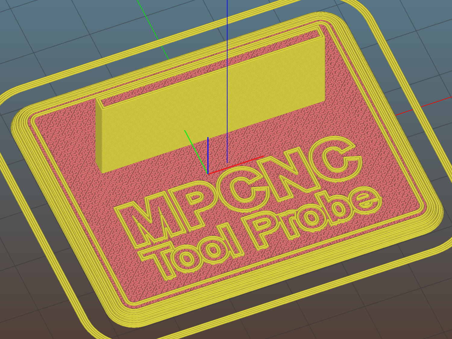
The flange offset puts the switch actuator on the midline of the base, not that that matters, and the base features rounded corners and a suitable legend, because I can.
I clipped the PCB’s through-hold leads nearly flush and stuck it to the flange with 3M permanent foam tape, which seems to work much better than screws & inserts for simple things that need never come apart.
The Protoneer CNC Shield includes a Probe input on the GRBL-compliant A5, although it took me a while to find the legend on the SCL pin in the I2C header. I moved the endstop power jumper to another header, then conjured a quick-and-dirty connector:
Protoneer CNC Shield – Tool Probe Wiring
When I embed the endstop switch PCB in epoxy, I’ll add a drop to the connector while engaging in Magical Thinking. The whole Arduino + CNC Shield must go into an enclosure after I finish measuring the motor currents.
To forestall discussions about switch repeatability and accuracy, suffice it to say the MPCNC doesn’t claim to be much more than a woodworking router, so those switches seem Good Enough.
This file contains hidden or bidirectional Unicode text that may be interpreted or compiled differently than what appears below. To review, open the file in an editor that reveals hidden Unicode characters.
Learn more about bidirectional Unicode characters
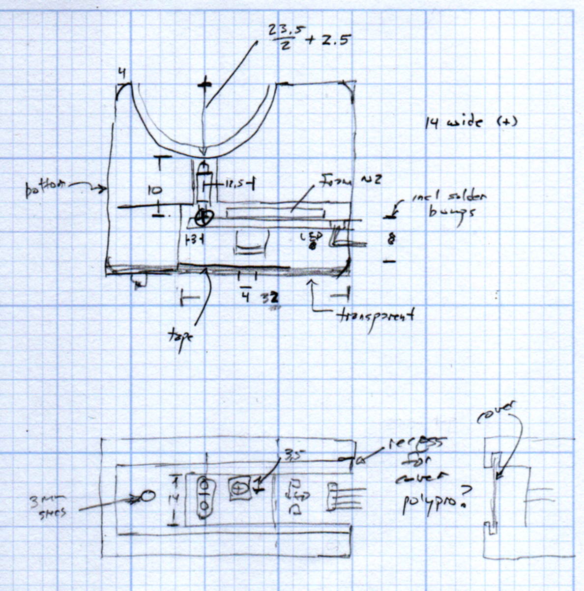
The original doodles show a severely over-complexicated solution desperately searching for an actual problem:
MPCNC Tool Length Probe – doodles
Putting a large flat pan at the end of a relatively long lever arm, with the pivot arranged to put the pan level at the switch actuation point, made sense at the time. Give the relatively small tools I expect to use, directly ramming them into the switch lever should work just as well.
Putting all that complexity in harm’s way seemed like a Bad Idea when I sat down and looked at it in cold blood.
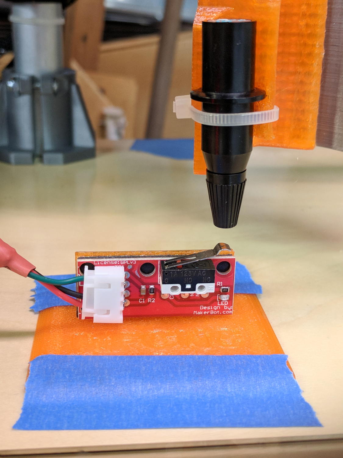
Homing the MPCNC’s Z axis at the bottom end of its travel made no sense, but the Z stage lacks a convenient spot to mount / trigger a switch at the top of its travel, so this sufficed for initial tests & fiddling:
MPCNC – Z min endstop
The EMT rail carrying the switch moves downward, tripping the lever when it hits the MPCNC’s central assembly.
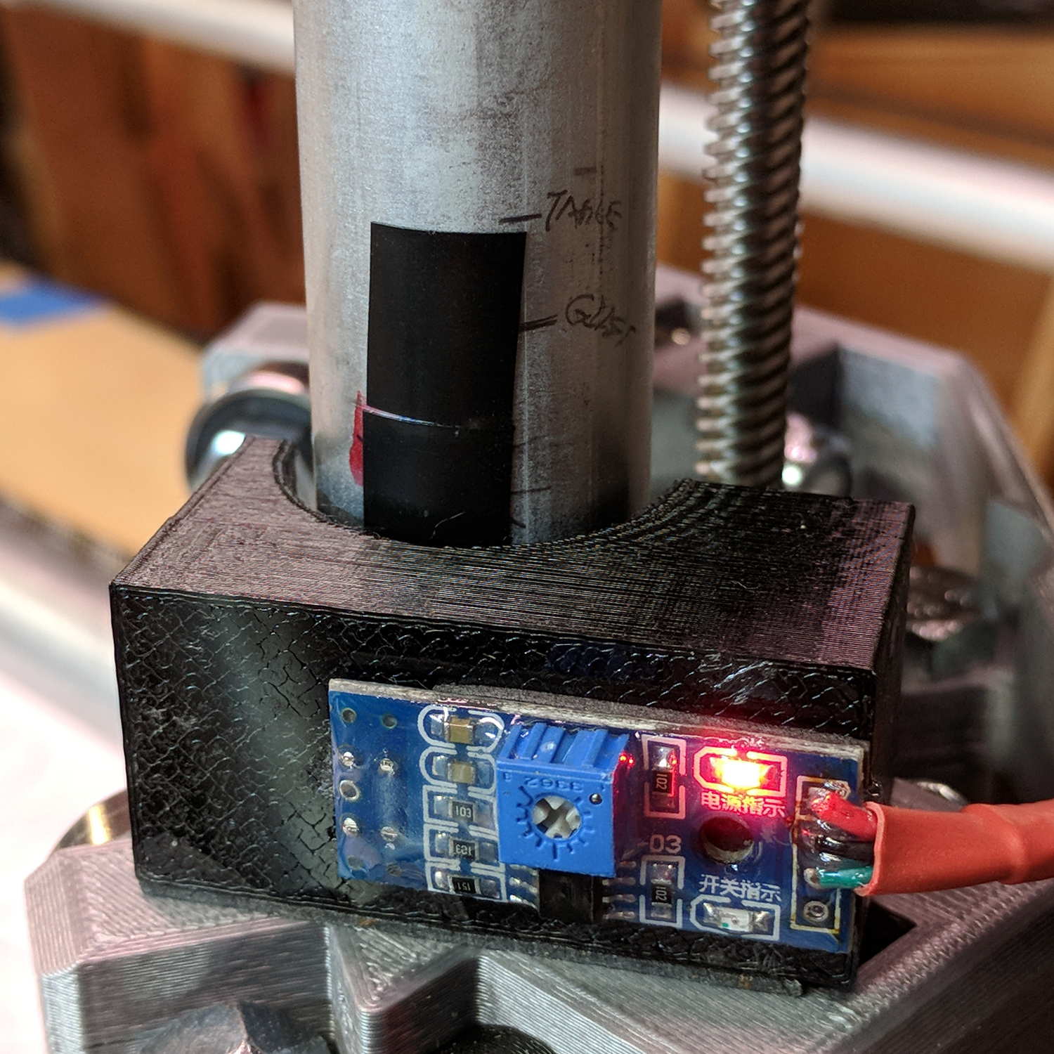
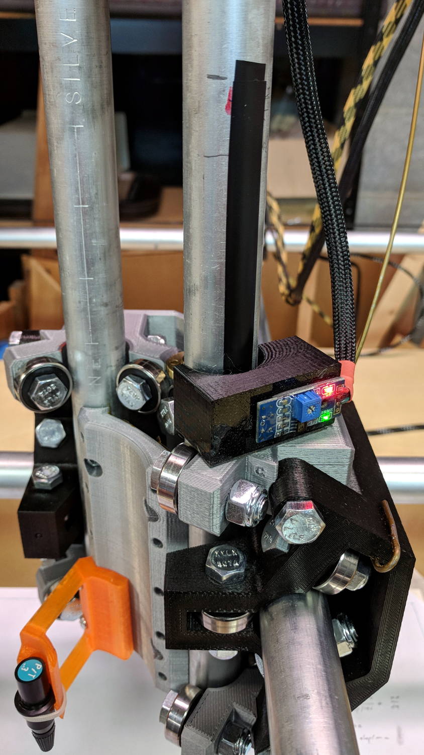
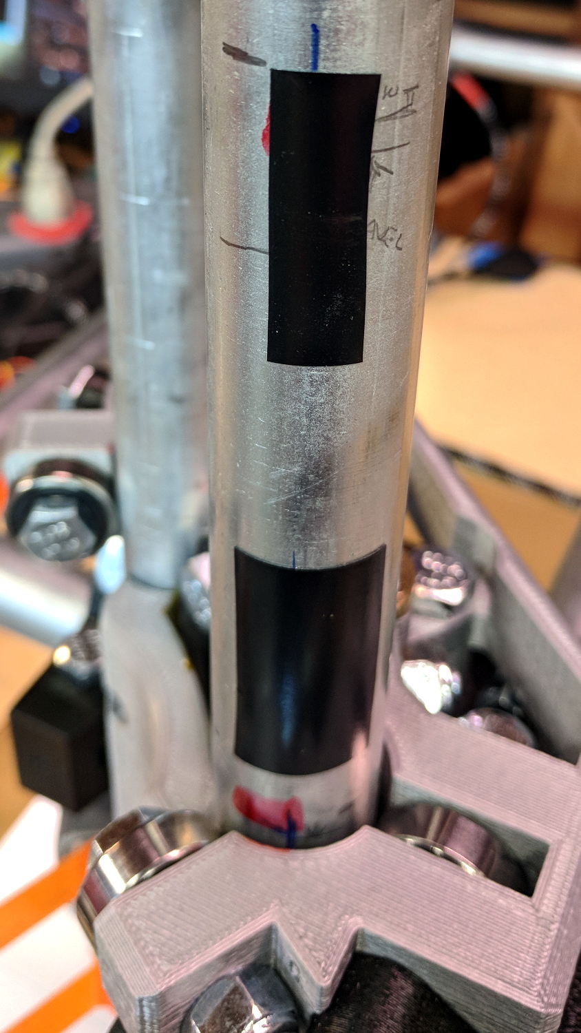
Somewhat to my surprise, a TRCT5000-based optical proximity sensor (harvested from the Kenmore 158 Crash Test Dummy’s corpse) and a strip of black electrical tape work perfectly:
I soldered the wires (harvested from the previous endstop) directly to the PCB, because the pinout isn’t the same and fewer connectors should be better.
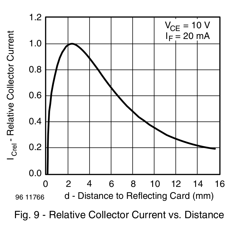
The mount uses black PETG, rather than translucent orange, in hope of IR opacity, and wraps around the EMT rail at (roughly) the 2 mm standoff producing the peak response:
IR Reflective Sensor module – TCRT5000 – response vs distance
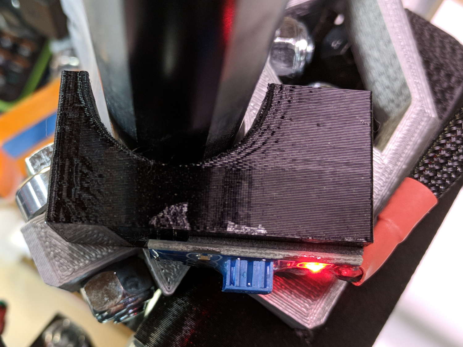
In truth, I set the gap by eyeballometric guesstimation to make the entire mount arc sit equidistant from the EMT:
MPCNC – Z Opto Prox Endstop – top view
The mount includes the 2 mm spacing around the EMT OD and puts the sensor tip flush with the arc OD, so it should be pretty close:
TCRT5000 Z Axis Endstop Mount – solid model
A strip of 3M permanent tape, cut to clear the 608 bearings, affixes the mount to the MPCNC’s central assembly. The solid model now includes a midline reference notch, with a height rounded up to the next-highest multiple of 2.0 mm. It needs a loop to anchor the cable.
The blue twiddlepot sets the comparator threshold midway between the response over black tape (incorrectly on = too low) and bare EMT (incorrectly off = too high), in the hope of noise immunity. The range spanned nearly half of the pot rotation, so I think it’s all good.
The sensor doesn’t trip when the edge of the tape exactly meets its midline, which meant I had to trim a strip of tape to suit. As part of setting the twiddlepot, I shut off the Z axis motor and laid some test strips on the EMT:
MPCNC – Z Axis Opto Prox Endstop – Test Tape
I spun the leadscrew with one hand, held the sensor with the other, twiddled the trimpot, trimmed the upper and lower ends of the tape, and generally had a fine time. The sensor responds equally well to a half-wide strip of tape (in the upper picture), with the distinct advantage of not encroaching on the 608 bearing tracks.
The GRBL setup now homes Y and Z toward the positive end of their travel, with X still toward the negative end while a set of extension cables remains in transit around the planet.
This file contains hidden or bidirectional Unicode text that may be interpreted or compiled differently than what appears below. To review, open the file in an editor that reveals hidden Unicode characters.
Learn more about bidirectional Unicode characters
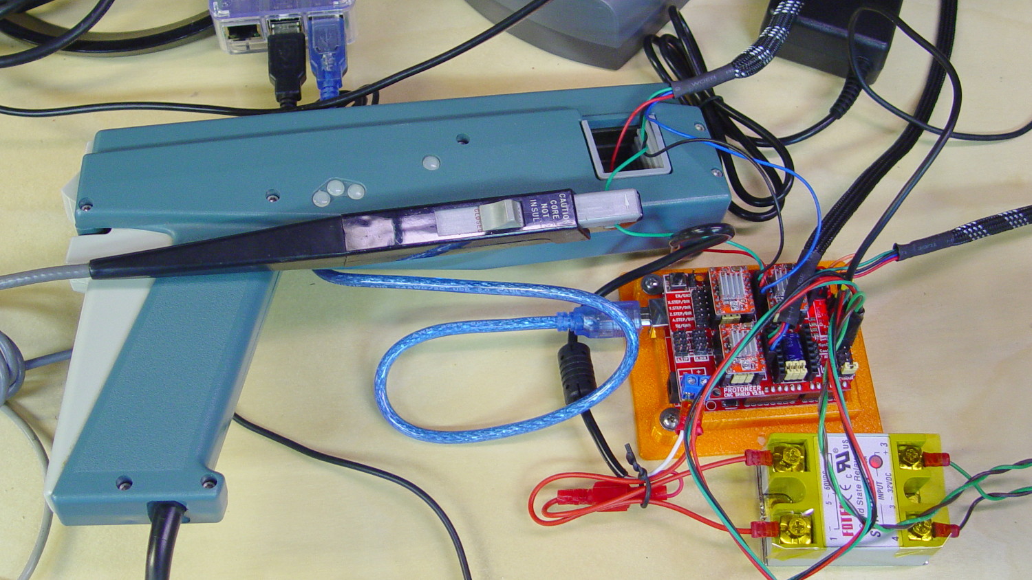
I measured stepper motor winding current with a pair of Tek Hall effect probes for future reference.
MPCNC – X Axis current measurement setup – overview
The pistol-shaped A6303 measures up to 100 A, so it’s grossly overqualified for the job. The much smaller A6302 goes to 20 A and is definitely the right hammer. The single-trace pix show 200 mA/div.
I’m using the default 12 V6 A MPCNC stepper power supply, with A4988 stepper driver boards on the Protoneer CNC Shield atop a knockoff Arduino UNO running GRBL firmware. The blue USB cable goes off to a Raspberry Pi running minicom for manual control.
All the pix use the same G-Code command: G1 X2.4 F180. Running at 180 mm/min = 3 mm/s eliminates pretty nearly all visible acceleration.
Each picture requires:
m9 to disable stepper power
Remove X axis A4988 driver board
Set jumpers to select new microstep mode
Reinstall driver board
Change GRBL $100 step/mm setting to match jumpers
Ctrl-X = reset GRBL
$x = unlock
m8 = enable power
Enable scope trigger (single-trigger mode)
g1x2.4f180 motion for next image
x0 = return to origin
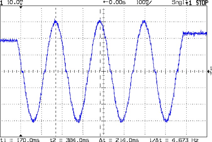
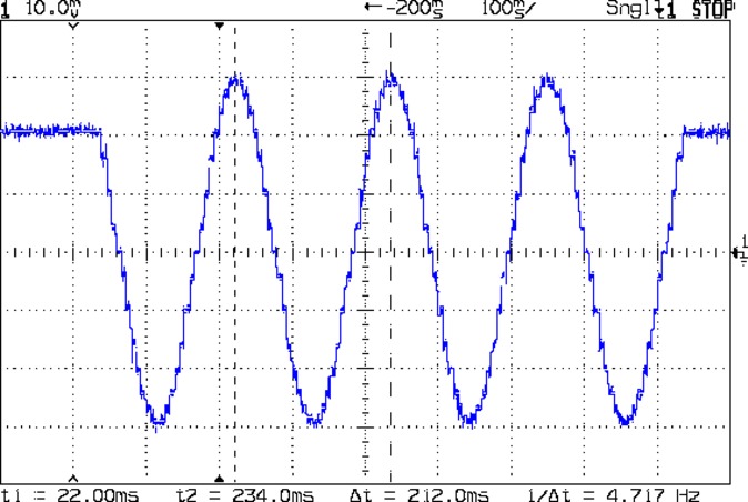
With the A4988 stepper driver in 16:1 microstep mode:
MPCNC g1x2.4f180 – 16 ustep – 200 mA-div
Notice how some of the microsteps aren’t particularly crisp, notably around the zero crossings. I think the relatively low 12 V supply doesn’t give the A4988 enough control authority to boss the current around, resulting in difficulty holding the current setpoint, even at low speed:
MPCNC X 10mm 60mm-s 500mA-div
More on that problem in a while.
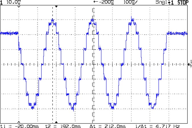
In 8:1 microstep mode:
MPCNC g1x2.4f180 – 8 ustep – 200 mA-div
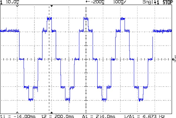
In 4:1 microstep mode:
MPCNC g1x2.4f180 – 4 ustep – 200 mA-div
In 2:1 microstep mode:
MPCNC g1x2.4f180 – 2 ustep – 200 mA-div
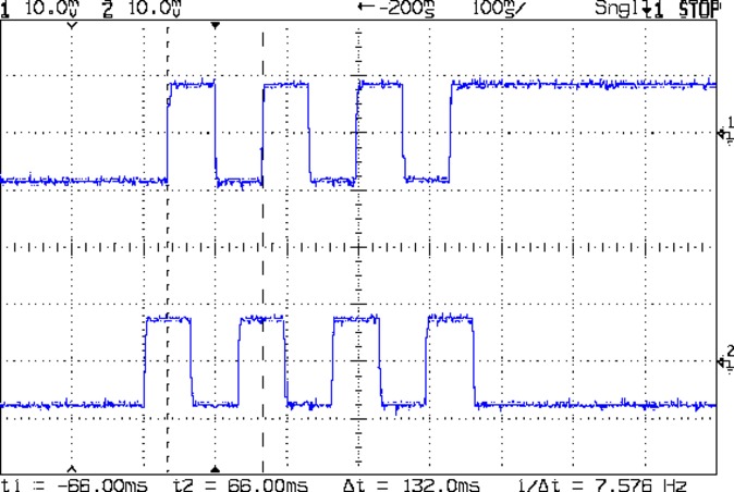
And, a rarity in modern times, both windingsat 500 mA/div in full step mode:
MPCNC g1x2.4f180 – 1 ustep – dual 500 mA-div
The A4988 driver reduces the peak current to 1/√2 of the stepped sine wave peak to maintain the same average power dissipation and torque. For reasons I cannot explain, the full-step move takes far less time than the others; it must have something to do with how GRBL computes the average speed. It sounds like a robotic woodpecker hammering on the MPCNC’s frame, so I flipped back to 16:1 microstep mode after taking that picture.
GRBL responds to critical errors by disabling its outputs, which seems like a useful feature for a big-enough-to-hurt CNC machine like the MPCNC. Unlike the RAMPS 1.4 board, there’s no dedicated power-control pin, so I connected the Coolant output to the same DC-DC SSR I tried out with the RAMPS board:
MPCNC – CNC Shield – Power SSR
With homing enabled, GRBL emerges from power-on resets and error conditions with the spindle and coolant turned off and the G-Code interpreter in a locked state requiring manual intervention, so turning the stepper power on fits right in:
$x – Unlock the controls
m8 – Coolant output on = enable stepper power
$h – Home all axes
The steppers go clunk as the power supply turns on, providing an audible confirmation. The dim red LED on the SSR isn’t particularly conspicuous.
Turning the stepper power off:
m9 – Coolant output off = disable stepper power
I think the A4988 drivers maintain their microstep position with the stepper power supply off, because their logic power remains on. In any event, you probably wouldn’t want to restart after an emergency stop without clearing the fault and re-homing the axes.
The board has Cycle Start, Feed Hold, and Abort inputs just crying out for big colorful pushbutton switches.
Unlike the RAMPS board, the Prontoneer CNC Shield does not feed stepper power to the underlying Arduino UNO, leaving it safely powered by USB or the coax jack.