I measured stepper motor winding current with a pair of Tek Hall effect probes for future reference.
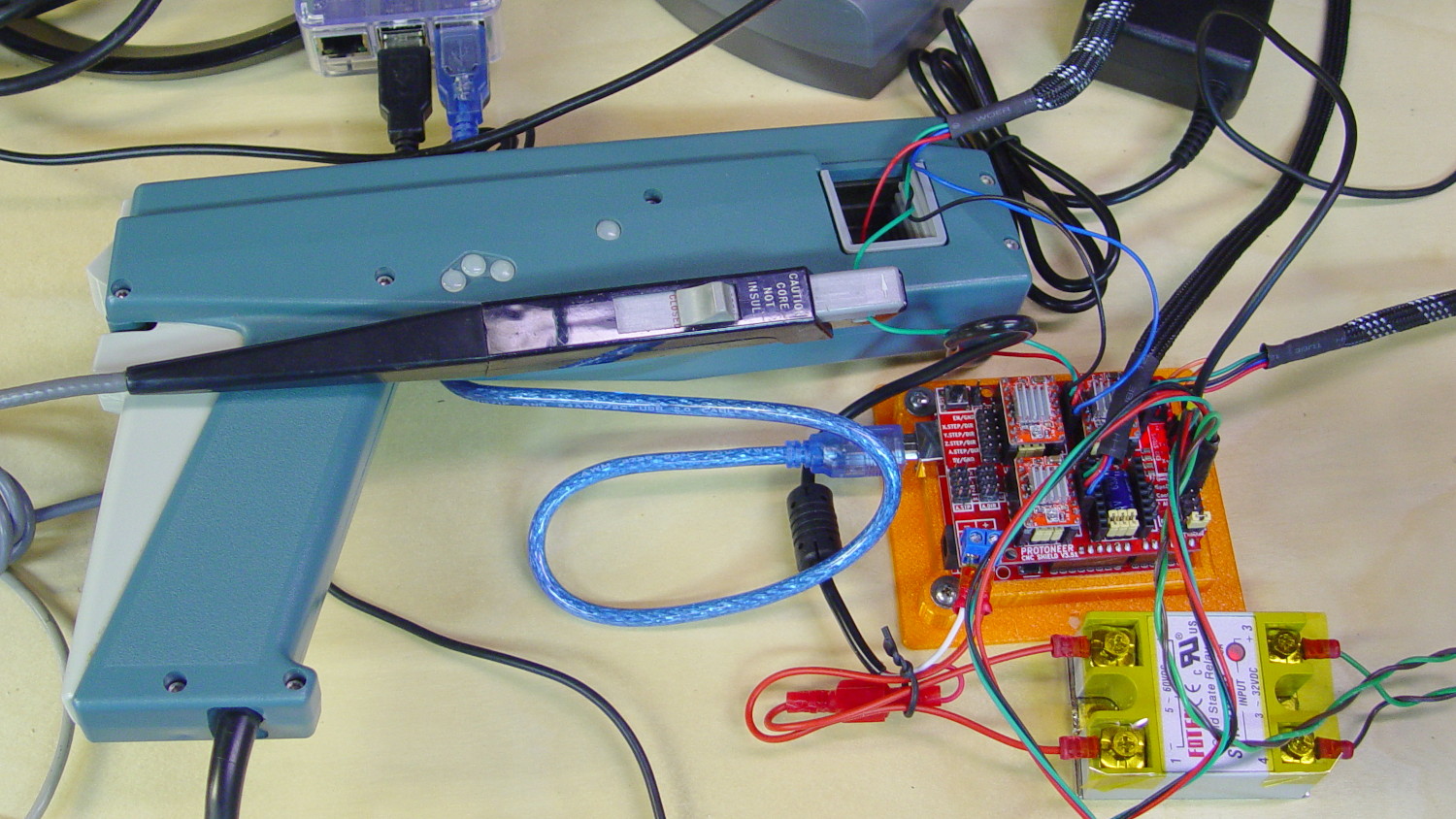
The pistol-shaped A6303 measures up to 100 A, so it’s grossly overqualified for the job. The much smaller A6302 goes to 20 A and is definitely the right hammer. The single-trace pix show 200 mA/div.
I’m using the default 12 V6 A MPCNC stepper power supply, with A4988 stepper driver boards on the Protoneer CNC Shield atop a knockoff Arduino UNO running GRBL firmware. The blue USB cable goes off to a Raspberry Pi running minicom for manual control.
All the pix use the same G-Code command: G1 X2.4 F180. Running at 180 mm/min = 3 mm/s eliminates pretty nearly all visible acceleration.
Each picture requires:
m9to disable stepper power- Remove X axis A4988 driver board
- Set jumpers to select new microstep mode
- Reinstall driver board
- Change GRBL $100 step/mm setting to match jumpers
Ctrl-X= reset GRBL$x= unlockm8= enable power- Enable scope trigger (single-trigger mode)
g1x2.4f180motion for next imagex0= return to origin
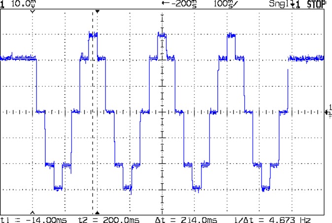
With the A4988 stepper driver in 16:1 microstep mode:
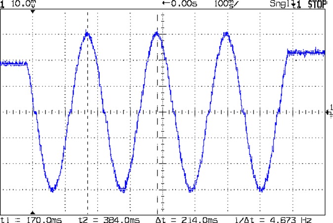
Notice how some of the microsteps aren’t particularly crisp, notably around the zero crossings. I think the relatively low 12 V supply doesn’t give the A4988 enough control authority to boss the current around, resulting in difficulty holding the current setpoint, even at low speed:

More on that problem in a while.
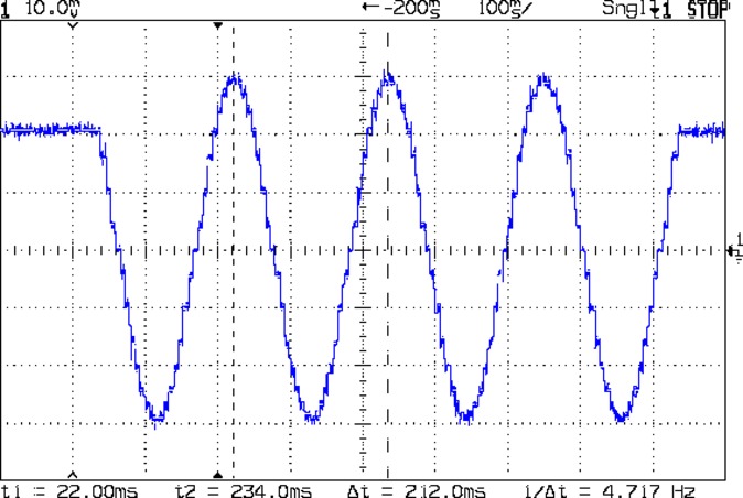
In 8:1 microstep mode:
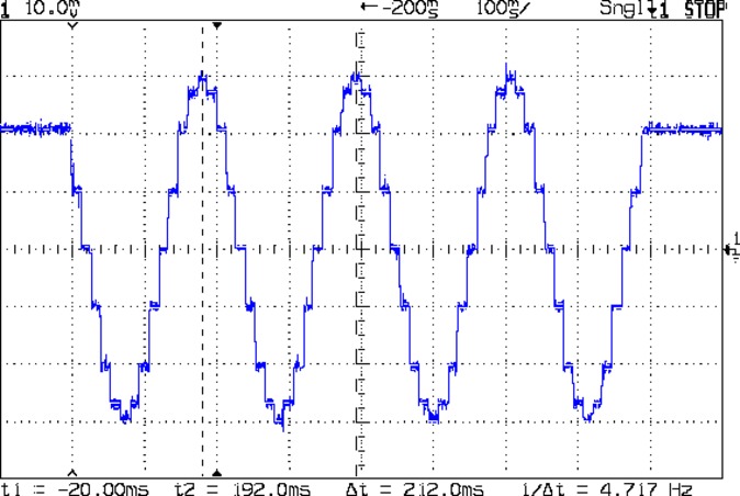
In 4:1 microstep mode:
In 2:1 microstep mode:
And, a rarity in modern times, both windings at 500 mA/div in full step mode:
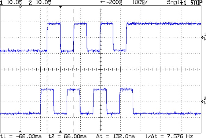
The A4988 driver reduces the peak current to 1/√2 of the stepped sine wave peak to maintain the same average power dissipation and torque. For reasons I cannot explain, the full-step move takes far less time than the others; it must have something to do with how GRBL computes the average speed. It sounds like a robotic woodpecker hammering on the MPCNC’s frame, so I flipped back to 16:1 microstep mode after taking that picture.
Now I can refer to these from elsewhere …
