The Smell of Molten Projects in the Morning

Ed Nisley's Blog: Shop notes, electronics, firmware, machinery, 3D printing, laser cuttery, and curiosities. Contents: 100% human thinking, 0% AI slop.

Tag: CNC

Making parts with mathematics

  • MPCNC: Z Height Probe

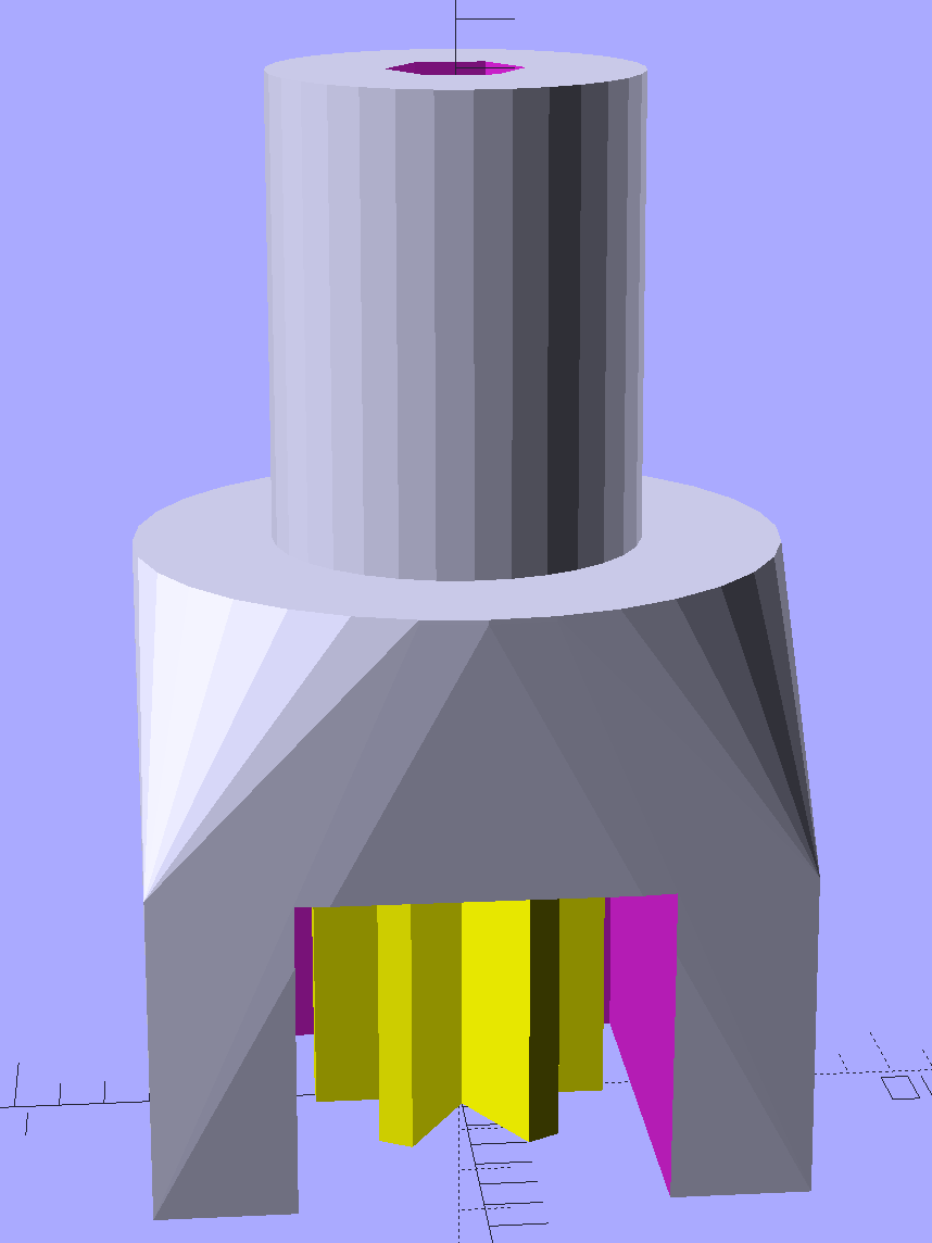
    A little support pillar makes a printable holder for a small tactile pushbutton:

    Z Axis Height Probe - solid model
    Z Axis Height Probe – solid model

    A(n) 0-80 brass washer epoxied atop the butt end of a P100-B1 pogo pin keeps the pin from falling out and provides a flat button pusher:

    MPCNC - Simple Z probe - push plate
    MPCNC – Simple Z probe – push plate

    With the epoxy mostly cured, ease the pin off the tape, flip the whole affair over, shove the switch into position, realign vertically with point down, then let the epoxy finish curing with the washer held in place against the switch to ensure good alignment:

    MPCNC - Simple Z probe - epoxy curing
    MPCNC – Simple Z probe – epoxy curing

    The brass tube ID is a sloppy fit around the pogo pin, but it’s also many pin diameters long and the position error isn’t worth worrying about.

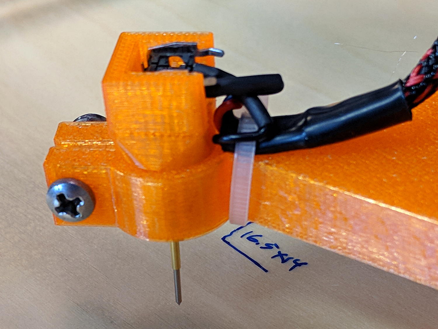
    Solder a cable, clamp it in the pen holder, attach to tool holder:

    MPCNC - Simple Z probe - installed
    MPCNC – Simple Z probe – installed

    The pogo pin provides half a dozen millimeters of compliance,  letting the initial probe speed be much higher than the tactile pushbutton’s overshoot could survive, after which a low-speed probe produces a consistent result.

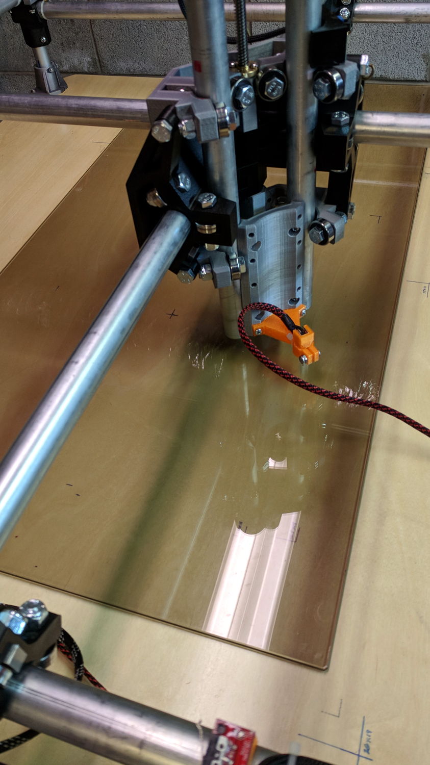
    Unleashing bCNC’s Autolevel probe cycle:

    MPCNC - Z-probing glass plate
    MPCNC – Z-probing glass plate

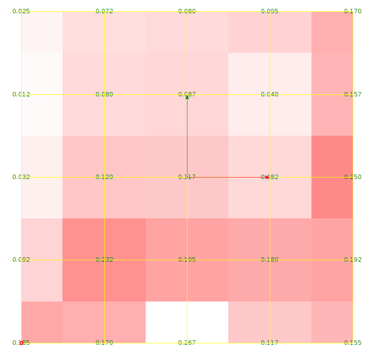
    Although the picture shows the MPCNC probing a glass plate, here’s the first height map taken from the bare workbench top with 100 mm grid spacing:

    ProbeArray-100-2018-01-04
    ProbeArray-100-2018-01-04

    The ridge along the right side comes from a visible irregularity in the wood grain, so the numbers actually represent a physical reality.

    Doing it with a 50 mm grid after re-probing the Z=0 level:

    ProbeArray-50-2018-01-04
    ProbeArray-50-2018-01-04

    Eyeballometrically, the second plot is 0.2 mm higher than the first, but this requires a bit more study.

    All in all, not bad for a first pass.


  • MPCNC: Pen Holder Crunch

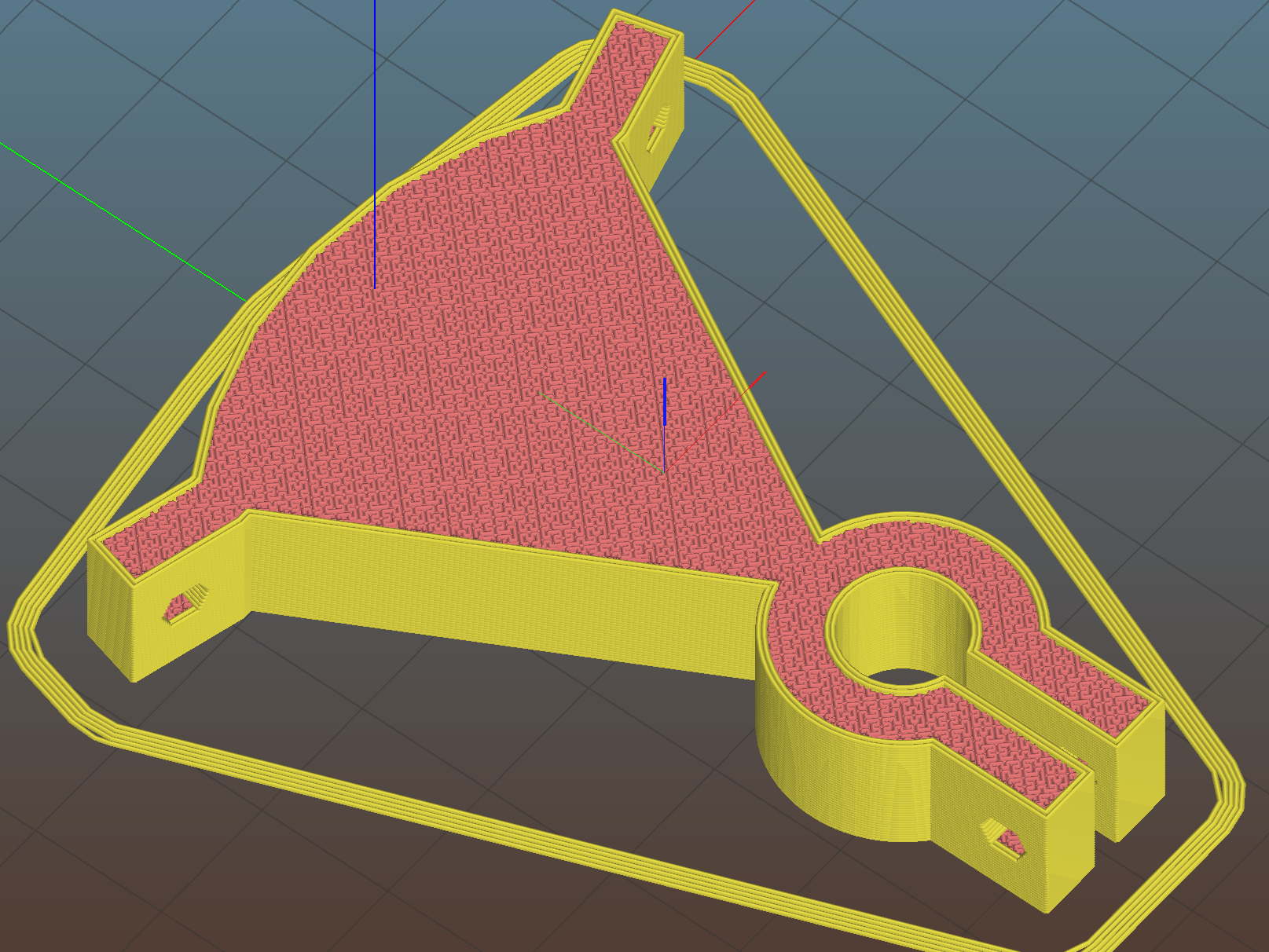
    A few tweaks to the Customizable MPCNC Mount for Round Tools produces a Sakura Micron pen holder:

    MPCNC - Sakura Pen Holder - Slic3r preview
    MPCNC – Sakura Pen Holder – Slic3r preview

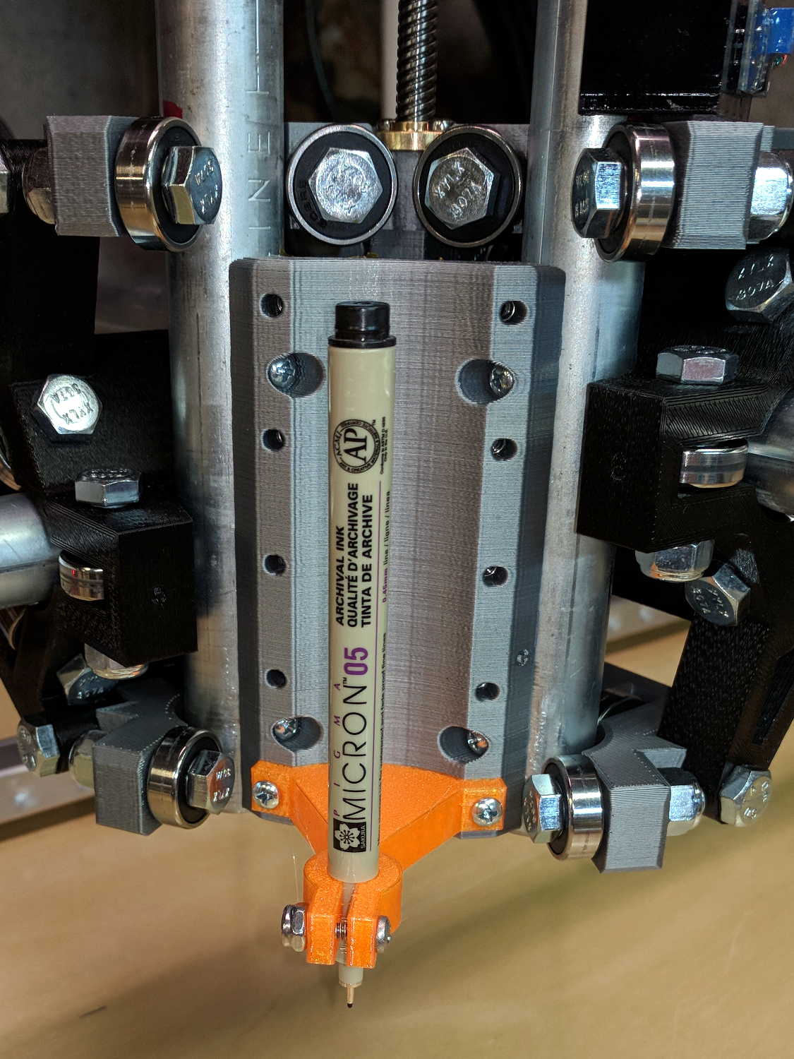
    The pen body seats atop the holder, with its narrower snout inside the clamp, giving positive control of the point position:

    MPCNC - Sakura in pen adapter
    MPCNC – Sakura in pen adapter

    Unfortunately, should one forget to zero the pen tip to the paper surface before starting a plot, Bad Things happen to good tips:

    MPCNC - Sakura pen - crushed tip
    MPCNC – Sakura pen – crushed tip

    The holder really needs at least a few millimeters of compliance, as a fiber-tip pen makes a fairly delicate tool not intended for applying much force at all to anything.

    But the holder might make a Z axis probe …

  • MPCNC: Rail Height Measurements and Plot Effects

    After once again figuring out how to read a vernier height gage, I measured the height of each end of the MPCNC rails:

    Brown and Sharpe 585 Height Gage
    Brown and Sharpe 585 Height Gage

    The process:

    • Position the gage near the end of the gantry’s travel
    • Twiddle the knurled ring to lower the probe (a.k.a. lathe bit) until …
    • It firmly captures the paper slip, then …
    • Twiddle the ring the other way until …
    • The paper barely moves
    • Read the vernier and take a picture

    So the numbers come out one paper thickness higher than the actual rail height; subtract 0.1 mm = 4 mil to get the true height:

    MPCNC Rail Height - 2017-12-23
    MPCNC Rail Height – 2017-12-23

    In round numbers, the difference is under 0.3 mm along each rail.

    The outer numbers on the lower sketch show the difference between each reading and the lowest value along that axis: the left rear corner is (roughly) 0.5 mm higher than the right front. The numbers inside the square give the additional height, rounded to sensible values, required to raise the low corners.

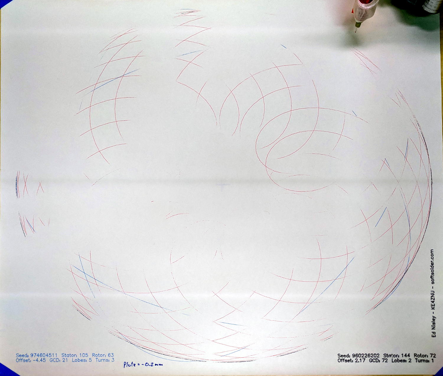
    Which means you can’t plot at, say, Z=-0.2 mm to reduce the pen loading, because the pen doesn’t uniformly touch the paper across the entire plot:

    MPCNC - Unlevel Z -0.2 plot
    MPCNC – Unlevel Z -0.2 plot

    These images have been perspective & aspect ratio corrected, then ruthlessly contrast-stretched to make the traces visible; the lighting isn’t that awful in person!

    With the plot at Z=-0.2, the legends toward the front came out OK, but they’re missing along the far edge. The Spirograph traces go completely missing toward the left rear as the pen rises away from the paper, although I think we’re also seeing some ripples in the paper sheet.

    Although such a small error probably makes no difference to a wood router, let’s see what we can do.

    Manually editing the G-Code to put successive traces at 0.1 mm increments from Z=-0.3 to Z=-0.6 mm, then replotting on the same piece of paper, shows the problem a bit better:

    MPCNC - Unlevel plot - multiple Z
    MPCNC – Unlevel plot – multiple Z

    All of the legends remain at Z=-0.2, because I wasn’t up for editing every pen-down command.

    Even at Z=-0.6 mm, the pen doesn’t quite touch in the left rear corner. Previously, I’d been plotting at a nice, round Z=-1.0 mm, which worked fine. I didn’t run any tests below Z=-0.6, but I think Z=-0.8 would draw a complete plot.

    That agrees reasonably well with the height gage measurements.

    It’s obviously impossible to re-level the rails by dinking around with the corner post lengths, because I can’t move the EMT in precise increments and it’d never stay in that position anyway. Instead, I should slide shims under the three lowest corner feet to raise them enough to match the left rear corner.

  • MPCNC: Emergency Stop / Feed Hold / Resume Pendant

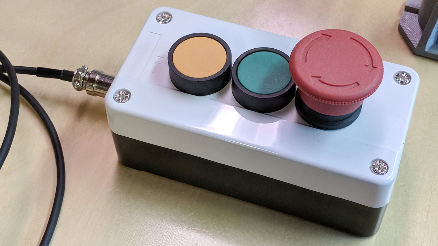
    The Protoneer CNC Shield has pin headers for GRBL’s Feed Hold and Resume inputs, so it seemed appropriate to put big buttons on the far end of the cable:

    MPCNC - E-stop Hold Resume switch box
    MPCNC – E-stop Hold Resume switch box

    The Emergency Stop Push Button Switch Station arrived for ten bucks delivered halfway around the planet.

    There’s not much to the wiring inside the box:

    MPCNC - E-Stop switch box - interior
    MPCNC – E-Stop switch box – interior

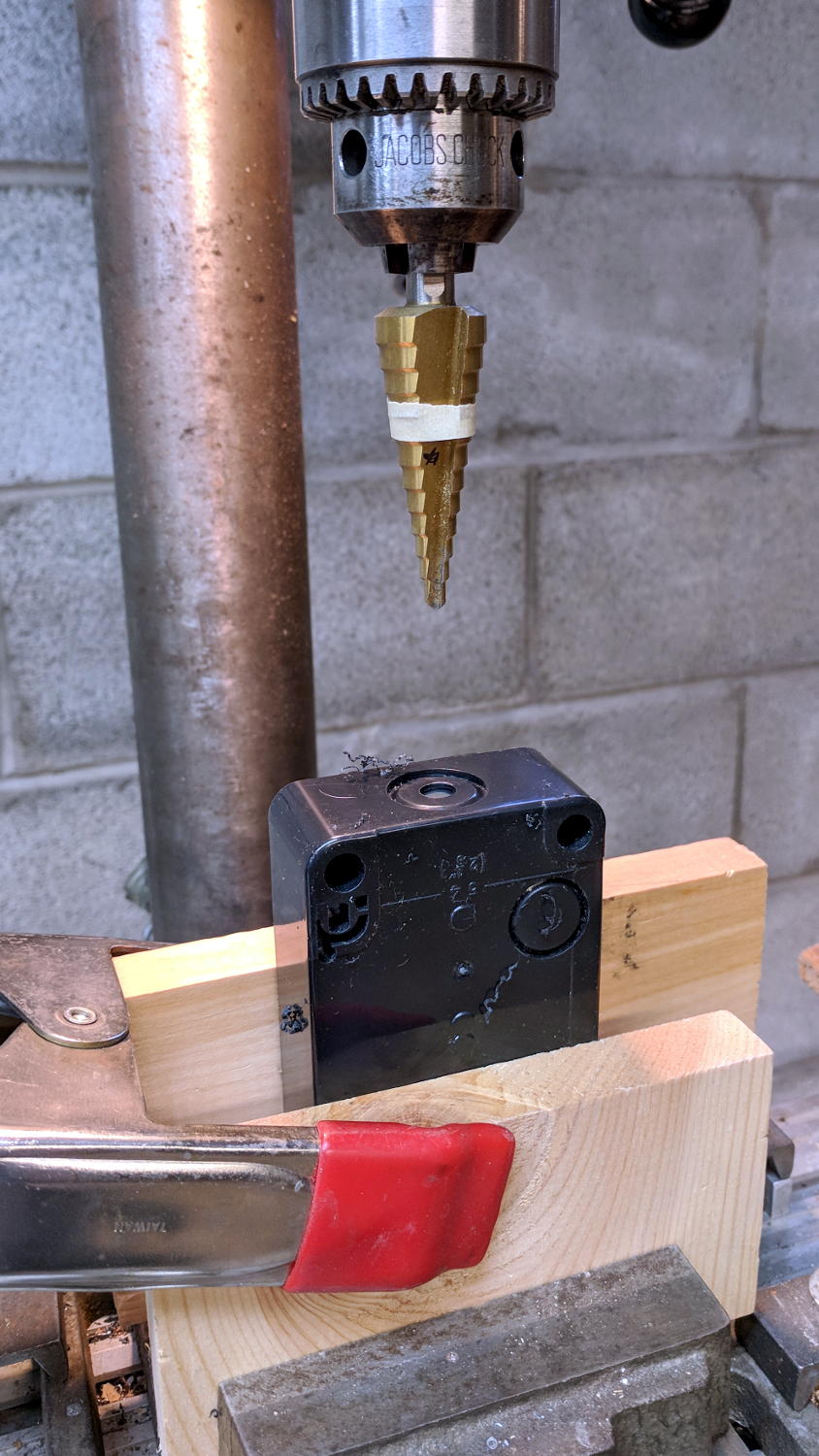
    I drilled a hole to fit the 6 pin Aviation Wire Connectors  I got for this very purpose:

    MPCNC - E-stop switch box - drilling
    MPCNC – E-stop switch box – drilling

    You could CNC machine a precise D-hole, but let’s stay realistic about the application. Applying a deburring tool enlarged the 9/16 inch hole enough to force the 16 mm threads into it, with the drill press holding the connector perpendicular to the box while I hand-turned the chuck to screw it in.

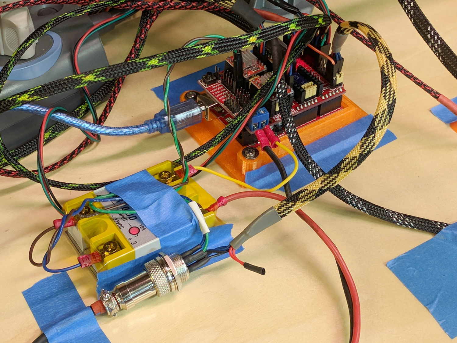
    Although I like the Protoneer CNC Shield, I really really dislike using header pins as connectors:

    MPCNC - Protoneer Wiring - SSR
    MPCNC – Protoneer Wiring – SSR

    Those pins are much too delicate.

    The DC-DC solid state relay input connects to the Arduino’s +5 V power supply through the red mushroom disconnect switch. The mushroom is normally closed to turn on the SSR and connect the power brick’s +24 V supply to the motors; it opens when slapped. GRBL will continue about its business, but without any power to the steppers the MPCNC will stop dead in its tracks. Turn the mushroom cap clockwise to unlatch and reset.

    The disconnect switch should also kill AC power to the router, when I get around to adding one to the mix, probably through a DC-AC SSR.

    AFAICT, the cable should come out of the box on the end with the mushroom switch, putting the “normal” pushbuttons closer to me. I did it the other way around, because I want the panic button to be the most easily reached thing on the benchtop. If I have time to think about it, I can reach around the mushroom to the Hold switch.

  • Spirograph Random Numbers: What Are The Odds?

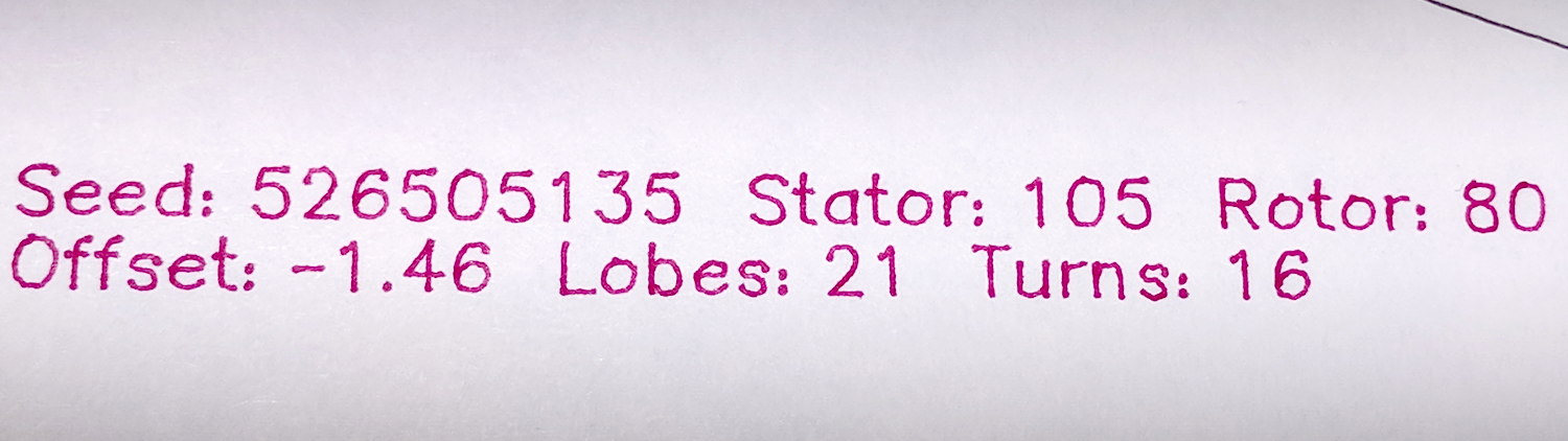
    The GCMC Spirograph Generator program chooses parameters using pseudo-random numbers based on a seed fed in from the Bash script, so I was surprised to see two plots overlap exactly:

    Overlaid pattern - G-Code simulator
    Overlaid pattern – G-Code simulator

    The two overlapping traces are the 15 inward-pointing wedges around the central rosette.

    The first one:

    (PRNG seed: 38140045)
    (Paper size: [16.50in,14in])
    (PlotSize: [15.50in,13.00in])
    (Stator 3: 150)
    (Rotor  4: 40)
    (GCD: 10)
    (Offset: -0.94)
    (Dia ratio: -0.27)
    (Lobes: 15)
    (Turns: 4)
    (Plot scale: [5.11in,4.29in])
    (Tool change: 1)
    T1
    M6
    

    The second one:

    (PRNG seed: 74359295)
    (Paper size: [16.50in,14in])
    (PlotSize: [15.50in,13.00in])
    (Stator 3: 150)
    (Rotor  4: 40)
    (GCD: 10)
    (Offset: -0.93)
    (Dia ratio: -0.27)
    (Lobes: 15)
    (Turns: 4)
    (Plot scale: [5.12in,4.30in])
    (Tool change: 3)
    T3
    M6
    

    The Offset isn’t quite the same, but the pen width covers up the difference.

    With only four Stators and 17 Rotors, the probability of picking the same pair works out to 0.25 × 0.059 = 1.4%. You can sometimes get the same number of Lobes and Turns from several different Stator + Rotor combinations, but these were exact matchs with the same indices.

    The Pen Offset within the Rotor comes from a fraction computed with ten bit resolution, so each Offset value represents slightly under 0.1% of the choices. If any four adjacent values look about the same, then it’s only eight bits of resolution and each represents 0.4%.

    The Rotor and Stator set the Diameter ratio, but the sign comes from what’s basically a coin flip based on the sign of a fraction drawn from 256 possibilities; call it 50%.

    Overall, you’re looking at a probability of 28 ppm = 0.0028%, so I (uh, probably) won’t see another overlay for a while …

    I don’t know how to factor the PRNG sequence into those numbers, although it surely affects the probability. In this case, two different seeds produced nearly the same sequence of output values, within the resolution of my hack-job calculations.

    Whatever. It’s good enough for my simple purposes!

  • MPCNC: Spirograph Generator with Tool Changes

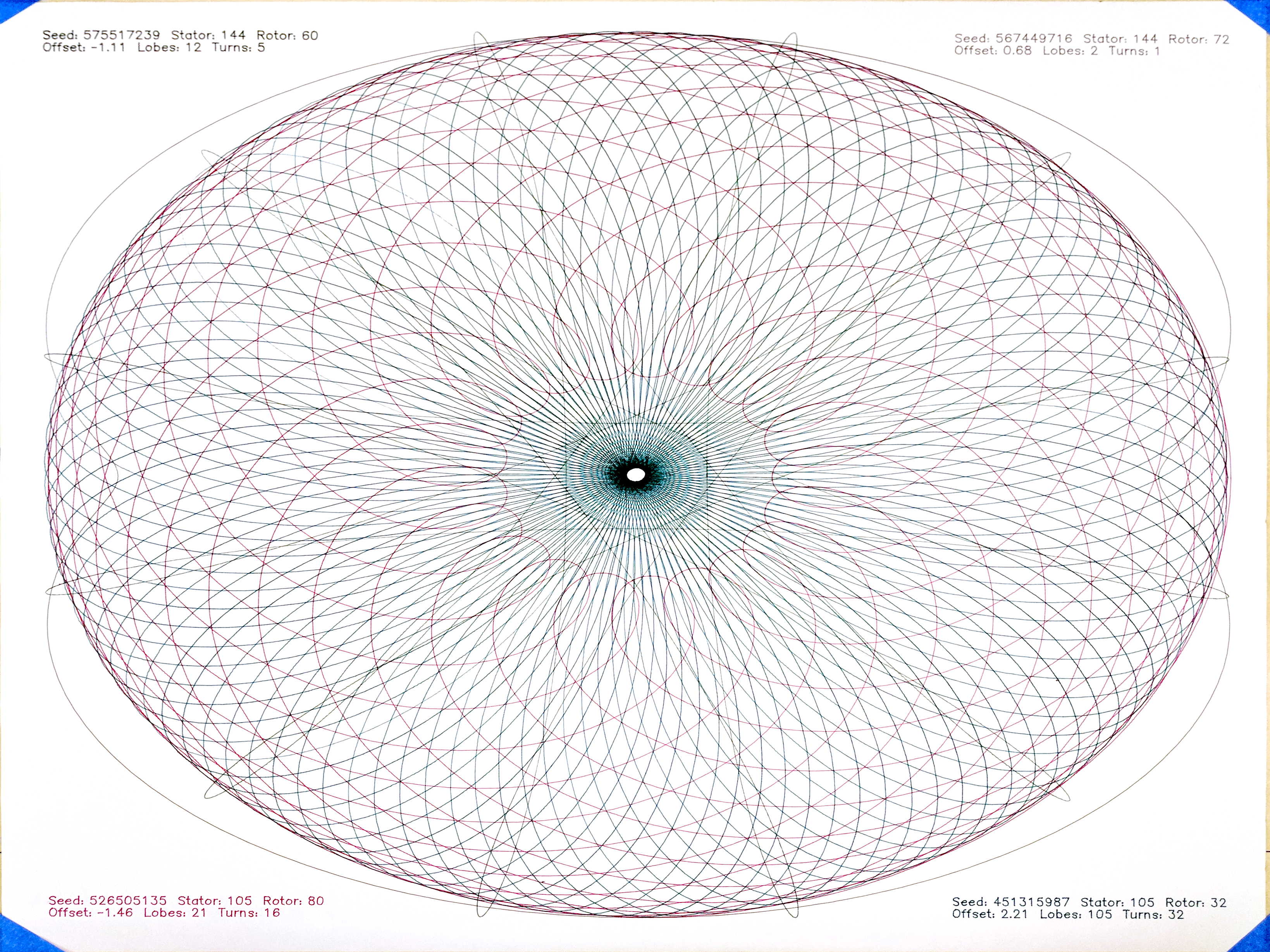
    An improved version of my GCMC Spirograph pattern generator, now with better annotation and tool changes:

    Spirograph pattern - overview
    Spirograph pattern – overview

    The GCMC code sets the stator and rotor gear tooth counts, the rotor diameter, and the pen offset using a pseudo-random number generator. This requires randomizing the PRNG seed, which I do in the calling script with the nanosecond of the current second: rnd=$(date +%N).

    The G-Code file name also comes from the timestamp:

    ts=$(date +%Y%m%d-%H%M%S)
    fn='Spiro_'${ts}'.ngc'
    # blank line to make the underscore visible
    

    Which means you must call the Bash script slowly to generate a pile o’ plots:

    for i in {1..60} ; do sh /mnt/bulkdata/Project\ Files/Mostly\ Printed\ CNC/Patterns/spiro.sh ; sleep 1 ; done
    

    Sift through the heap with drag-n-drop action using an online G-Code previewer. There seems no clean way to convert G-Code to a bitmap on the command line, although you can do it manually, of course.

    The GCMC program spits out the G-code for one plot at a time, so the Bash script calls it four times to fill a sheet of paper with random patterns:

    for p in $(seq 4)
    do
      rnd=$(date +%N)
      gcmc -D Pen=$p -D $Paper -D PRNG_Seed=$rnd $Flags $LibPath -q "$Spirograph" >> $fn
    done
    

    The -q parameter tells GCMC to not include the prolog and epilog files, because the calling script glues those onto the lump of G-Code for all four plots.

    The -D Pen=$p parameter tells the GCMC program which “tool” to select with a Tn M6 tool change command before starting the plot. Although plotter pens have a well-defined position in the holder and a pretty nearly constant length, you must have a tool length probe installed and configured:

    MPCNC Tool Length Probe - Plotter Pen
    MPCNC Tool Length Probe – Plotter Pen

    Set the overall sheet size in inches or millimeters to get a plot centered in the middle of the page with half-inch margins all around:

    Paper='PaperSize=[16.5in,14in]
    

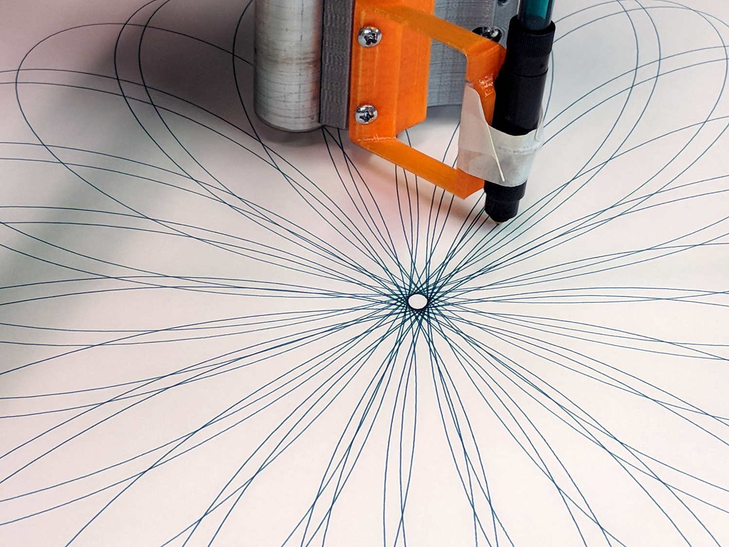
    With all that in hand, those good old black ceramic-tip pens give impeccable results:

    Spirograph pattern - black ceramic pen - detail
    Spirograph pattern – black ceramic pen – detail

    The surviving ones, anyhow. I must apply my collection of Sakura Micron pens to this task.

    The other three colors come from fiber pens with reasonably good tips:

    Spirograph pattern - central details
    Spirograph pattern – central details

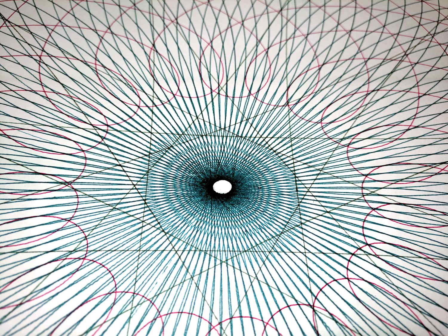
    They’re a lot like diatoms: all different and all alike.

    The GCMC and Bash source code as a GitHub Gist:

    # Spirograph G-Code Generator
    # Ed Nisley KE4ZNU – December 2017
    Paper='PaperSize=[16.5in,14in]'
    Flags="-P 2"
    LibPath="-I /opt/gcmc/library"
    Spirograph='/mnt/bulkdata/Project Files/Mostly Printed CNC/Patterns/Spirograph.gcmc'
    Prolog="/home/ed/.config/gcmc/prolog.gcmc"
    Epilog="/home/ed/.config/gcmc/epilog.gcmc"
    ts=$(date +%Y%m%d-%H%M%S)
    fn='Spiro_'${ts}'.ngc'
    echo Output: $fn
    rm -f $fn
    echo "(File: "$fn")" > $fn
    cat $Prolog >> $fn
    for p in $(seq 4)
    do
    rnd=$(date +%N)
    gcmc -D Pen=$p -D $Paper -D PRNG_Seed=$rnd $Flags $LibPath -q "$Spirograph" >> $fn
    done
    cat $Epilog >> $fn
    view raw spiro.sh hosted with ❤ by GitHub
    // Spirograph simulator for MPCNC used as plotter
    // Ed Nisley KE4ZNU – 2017-12-23
    // Spirograph equations:
    // https://en.wikipedia.org/wiki/Spirograph
    // Loosely based on GCMC cycloids.gcmc demo:
    // https://gitlab.com/gcmc/gcmc/tree/master/example/cycloids.gcmc
    // Required command line parameters:
    // -D Pen=n pen selection for tool change and legend position
    // -D PaperSize=[x,y] overall sheet size: [17in,11in]
    // -D PRNG_Seed=i non-zero random number seed
    include("tracepath.inc.gcmc");
    include("engrave.inc.gcmc");
    //—–
    // Greatest Common Divisor
    // https://en.wikipedia.org/wiki/Greatest_common_divisor#Using_Euclid's_algorithm
    // Inputs = integers without units
    function gcd(a,b) {
    local d=0;
    if (!isnone(a) || isfloat(a) || !isnone(b) || isfloat(b)) {
    warning("Values must be dimensionless integers");
    }
    while (!((a | b) & 1)) { // remove and tally common factors of two
    a >>= 1;
    b >>= 1;
    d++;
    }
    while (a != b) {
    if (!(a & 1)) {a >>= 1;} // discard non-common factor of 2
    elif (!(b & 1)) {b >>= 1;} // … likewise
    elif (a > b) {a = (a – b) >> 1;} // gcd(a,b) also divides a-b
    else {b = (b – a) >> 1;} // … likewise
    }
    local GCD = a*(1 << d); // form gcd
    // message("GCD: ",GCD);
    return GCD;
    }
    //—–
    // Max and min functions
    function max(x,y) {
    return (x > y) ? x : y;
    }
    function min(x,y) {
    return (x < y) ? x : y;
    }
    //—–
    // Pseudo-random number generator
    // Based on xorshift:
    // https://en.wikipedia.org/wiki/Xorshift
    // http://www.jstatsoft.org/v08/i14/paper
    // Requires initial state from calling script
    // -D "PRNG_Seed=$(date +%N)"
    function XORshift() {
    local x = PRNG_State;
    x ^= x << 13;
    x ^= x >> 17;
    x ^= x << 5;
    PRNG_State = x;
    return x;
    }
    //—–
    // Spirograph tooth counts mooched from:
    // http://nathanfriend.io/inspirograph/
    // Stators has both inside and outside counts, because we're not fussy
    Stators = [96, 105, 144, 150];
    Rotors = [24, 30, 32, 36, 40, 45, 48, 50, 52, 56, 60, 63, 64, 72, 75, 80, 84];
    //—–
    // Start drawing things
    // Set these variables from command line
    comment("PRNG seed: ",PRNG_Seed);
    PRNG_State = PRNG_Seed;
    // Define some useful constants
    AngleStep = 2.0deg;
    Margins = [0.5in,0.5in] * 2;
    comment("Paper size: ",PaperSize);
    PlotSize = PaperSize – Margins;
    comment("PlotSize: ",PlotSize);
    //—–
    // Set up gearing
    s = (XORshift() & 0xffff) % count(Stators);
    StatorTeeth = Stators[s];
    comment("Stator ",s,": ",StatorTeeth);
    r = (XORshift() & 0xffff) % count(Rotors);
    RotorTeeth = Rotors[r];
    comment("Rotor ",r,": ",RotorTeeth);
    GCD = gcd(StatorTeeth,RotorTeeth); // reduce teeth to ratio of least integers
    comment("GCD: ",GCD);
    StatorN = StatorTeeth / GCD;
    RotorM = RotorTeeth / GCD;
    L = to_float((XORshift() & 0x3ff) – 512) / 100.0; // normalized pen offset in rotor
    comment("Offset: ", L);
    sgn = sign((XORshift() & 0xff) – 128);
    K = sgn*to_float(RotorM) / to_float(StatorN); // normalized rotor dia
    comment("Dia ratio: ",K);
    Lobes = StatorN; // having removed all common factors
    Turns = RotorM;
    comment("Lobes: ", Lobes);
    comment("Turns: ", Turns);
    //—–
    // Crank out a list of points in normalized coordinates
    Path = {};
    Xmax = 0.0;
    Xmin = 0.0;
    Ymax = 0.0;
    Ymin = 0.0;
    for (a=0.0deg ; a <= Turns*360deg ; a += AngleStep) {
    x = (1 – K)*cos(a) + L*K*cos(a*(1 – K)/K);
    if (x > Xmax) {Xmax = x;}
    elif (x < Xmin) {Xmin = x;}
    y = (1 – K)*sin(a) – L*K*sin(a*(1 – K)/K);
    if (y > Ymax) {Ymax = y;}
    elif (y < Ymin) {Ymin = y;}
    Path += {[x,y]};
    }
    //message("Max X: ", Xmax, " Y: ", Ymax);
    //message("Min X: ", Xmin, " Y: ", Ymin); // min will always be negative
    Xmax = max(Xmax,-Xmin); // odd lobes can cause min != max
    Ymax = max(Ymax,-Ymin); // … need really truly absolute maximum
    //—–
    // Scale points to actual plot size
    PlotScale = [PlotSize.x / (2*Xmax), PlotSize.y / (2*Ymax)];
    comment("Plot scale: ", PlotScale);
    Points = scale(Path,PlotScale); // fill page, origin at center
    //—–
    // Set up pen
    if (Pen > 0) {
    comment("Tool change: ",Pen);
    toolchange(Pen);
    }
    //—–
    // Plot the curve
    feedrate(3000.0mm);
    safe_z = 1.0mm;
    plot_z = -1.0mm;
    tracepath(Points, plot_z);
    //—–
    // Put legend in proper location
    feedrate(500mm);
    TextSize = [3.0mm,3.0mm];
    TextLeading = 1.5; // line spacing as multiple of nominal text height
    MaxPen = 4;
    line1 = typeset("Seed: " + PRNG_Seed + " Stator: " + StatorTeeth + " Rotor: " + RotorTeeth,FONT_HSANS_1);
    line2 = typeset("Offset: " + L + " GCD: " + GCD + " Lobes: " + Lobes + " Turns: " + Turns,FONT_HSANS_1);
    maxlength = TextSize.x * max(line1[-1].x,line2[-1].x);
    textpath = line1 + (line2 – [-, TextLeading, -]); // undef – n -> undef to preserve coordinates
    if (Pen == 1 || Pen > MaxPen ) { // catch and fix obviously bogus pen selections
    textorg = [PlotSize.x/2 – maxlength,-(PlotSize.y/2 – TextLeading*TextSize.y)];
    }
    elif (Pen == 2) {
    textorg = [-PlotSize.x/2,-(PlotSize.y/2 – TextLeading*TextSize.y)];
    }
    elif (Pen == 3) {
    textorg = [PlotSize.x/2 – maxlength, PlotSize.y/2 – TextSize.y];
    }
    elif (Pen == 4) {
    textorg = [-PlotSize.x/2, PlotSize.y/2 – TextSize.y];
    }
    else {
    Pen = 0; // squelch truly bogus pens
    textorg = [0mm,0mm]; // just to define it
    }
    if (Pen) { // Pen = 0 suppresses legend
    placepath = scale(textpath,TextSize) + textorg;
    comment("Legend begins");
    engrave(placepath,safe_z,plot_z);
    }
    if (Pen == 1) { // add attribution along right margin
    attrpath = typeset("Ed Nisley – KE4ZNU – softsolder.com",FONT_HSANS_1);
    attrpath = rotate_xy(attrpath,90deg);
    attrorg = [PlotSize.x/2,5*TextLeading*TextSize.y – PlotSize.y/2];
    placepath = scale(attrpath,TextSize) + attrorg;
    comment("Attribution begins");
    engrave(placepath,safe_z,plot_z);
    }
    goto([-,-,25.0mm]);
    view raw Spirograph.gcmc hosted with ❤ by GitHub
  • A Spirograph for Christmas

    Gotta play with my new toy:

    Spirograph - liquid ink - ceramic tip
    Spirograph – liquid ink – ceramic tip

    That’s with a set of liquid ink and ceramic tip plotter pens. They’re unbelievably cranky, but produce wonderfully fine lines:

    Spirograph - liquid ink pen - detail
    Spirograph – liquid ink pen – detail

    Text comes out exactly the way vector lettering should look:

    Spirograph - liquid ink pen text - detail
    Spirograph – liquid ink pen text – detail

    There’s a slight shake visible at 500 mm/min = 8.3 mm/s, but it’s Good Enough.

    All the pen-and-ink traffic around the center produced a ring of damp green fuzz:

    Spirograph - liquid ink - ceramic tip - center detail
    Spirograph – liquid ink – ceramic tip – center detail

    The artsy part of the plot ran at 1800 mm/min = 30 mm/s, with little of the wobbulation at 6000 mm/min = 100 mm/s. None of that would matter with a router, of course.

    It’s a nice, Christmasy design in kinda-red and sorta-green.

    From the stack of plots accumulating near the MPCNC bench:

    This slideshow requires JavaScript.

    Plots 7 and 9 show the tape sutures required to produce a 26×18 inch sheet covering the MPCNC’s full work area. The squat plots fit on B-size sheets and the rest come from 17×14 inch artist’s sketchpad sheets.

    I used Google PhotoScan to capture and rectangularize paper sheets from the floor or atop the bench, then battered the contrast and crushed the file size with a one-liner:

    i=1 ; for f in 1* ; do printf -v dn "Spiro %02d.jpg" $(( i++ )) ; convert $f -level '10,80%' -density 300 -define jpeg:extent=300KB tweaked/"$dn" ; done
    

    The plots look great in person (modulo some incremental software improvements), but the slideshow images look awful because:

    • Google PhotoScan produces surprisingly low-res images
    • I’m overly compressing the results

    They’re not (yet) art and there’s no point in a high-quality workflow.

    Enjoy the day …