The Smell of Molten Projects in the Morning

Ed Nisley's Blog: Shop notes, electronics, firmware, machinery, 3D printing, laser cuttery, and curiosities. Contents: 100% human thinking, 0% AI slop.

Tag: CNC

Making parts with mathematics

  • Mostly Printed CNC: Endstop Mount

    Being a big fan of having a CNC machine know where it is, adding endstops (pronounded “home switches” in CNC parlance) to the Mostly Printed CNC axes seemed like a good idea:
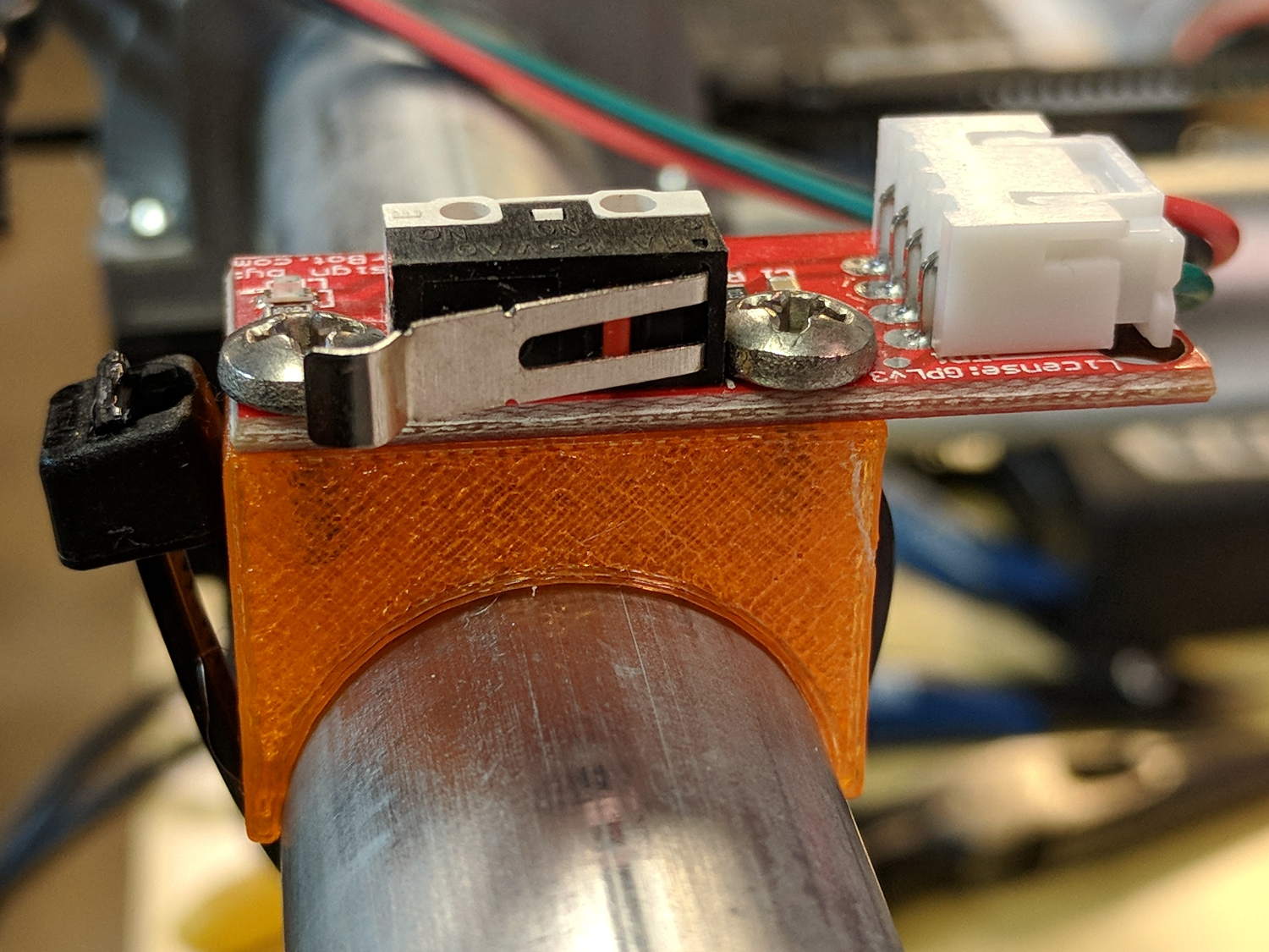
    MPCNC - X min endstop - actuator view
    MPCNC – X min endstop – actuator view

    All the mounts I could find fit bare microswitches of various sizes or seemed overly complex & bulky for what they accomplished. Rather than fiddle with screws and nut traps / inserts, a simple cable tie works just fine and makes the whole affair much smaller. Should you think cable ties aren’t secure enough, a strip of double stick tape will assuage your doubts.

    A snippet of aluminum sheet moves the switch trip point out beyond the roller’s ball bearing:
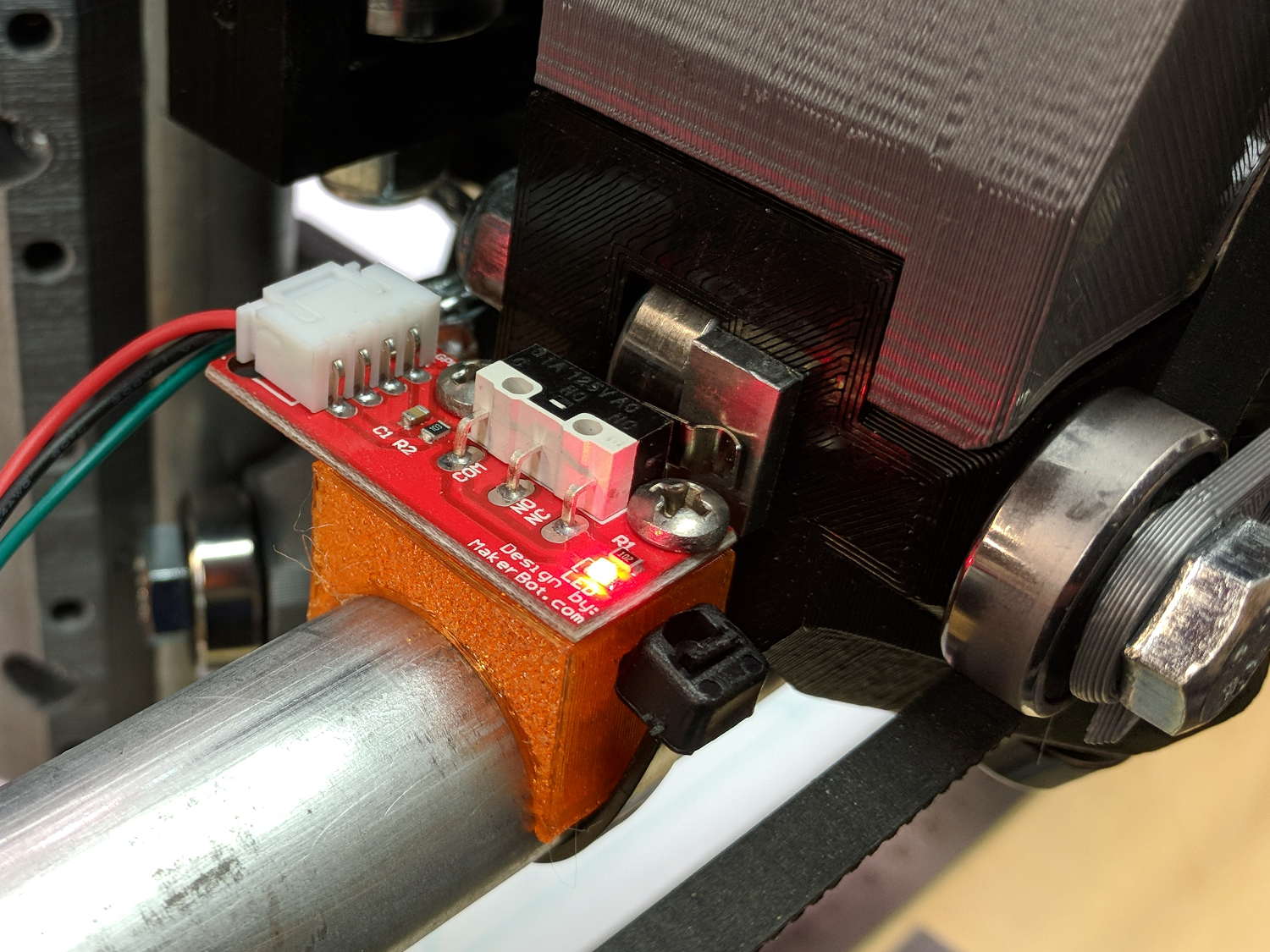
    MPCNC - X min endstop
    MPCNC – X min endstop

    I’m not convinced homing the Z axis at the bottom of its travel is the right thing to do, but it’s a start:

    MPCNC - Z min endstop
    MPCNC – Z min endstop

    Unlike the stationary X and Y axes, the MPCNC’s Z axis rails move vertically in the middle block assembly; the switch moves downward on the rail until the actuator hits the block.

    Perforce, the tooling mounted on the Z axis must stick out below the bottom of the tool carrier, which means the tool will hit the table before the switch hits the block. There should also be a probe input to support tool height setting.

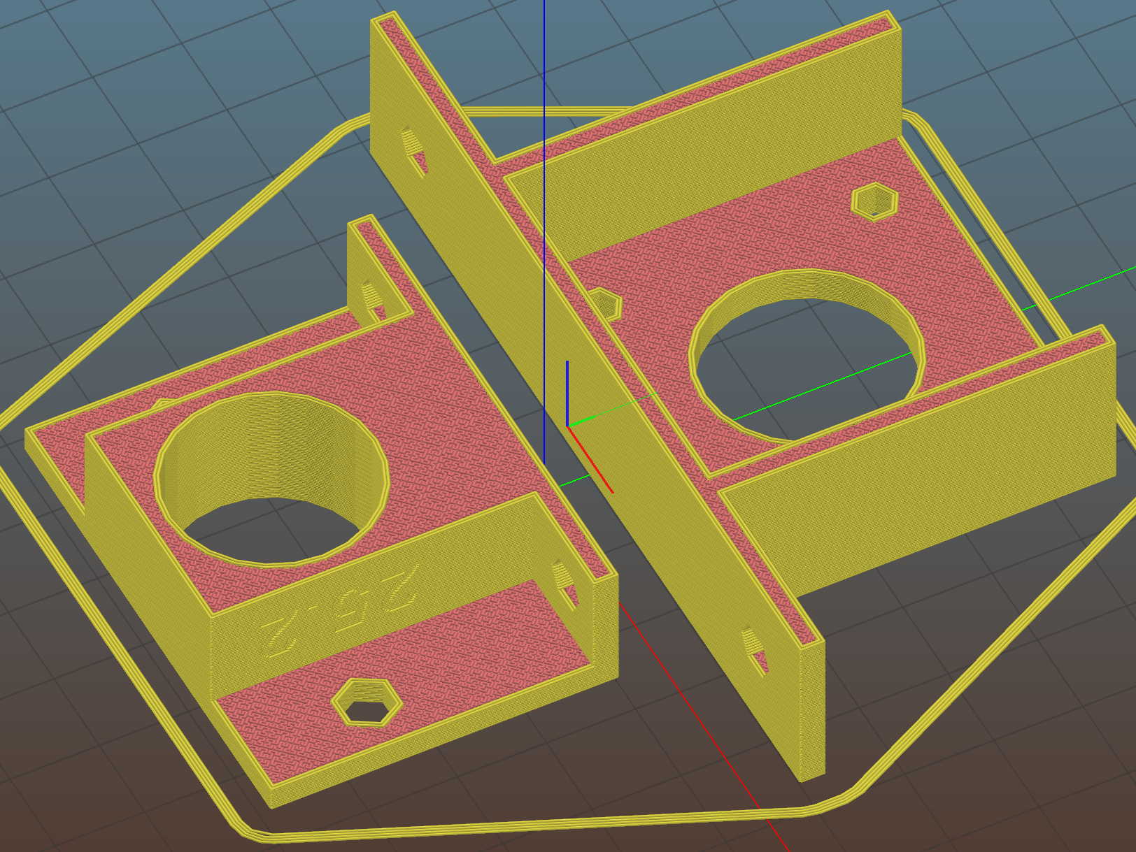
    The first mount fit perfectly, so I printed four more in one pass:
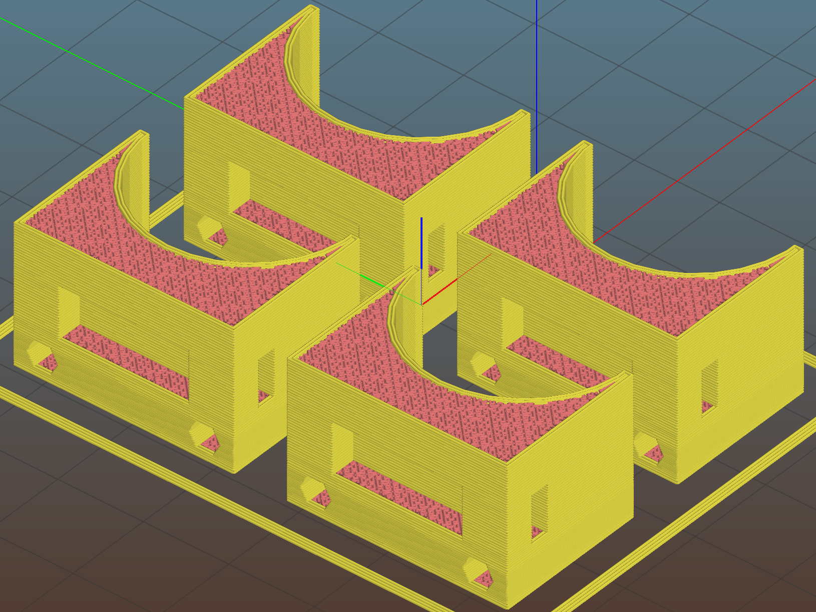
    MPCNC MB Endstop Mounts - Slic3r preview
    MPCNC MB Endstop Mounts – Slic3r preview

    All three endstops plug into the RAMPS board, leaving the maximum endstop connections vacant:

    MPCNC - RAMPS min endstop positions
    MPCNC – RAMPS min endstop positions

    Obviously, bare PCBs attached to the rails in mid-air aren’t compatible with milling metal, which I won’t be doing for quite a while. The electronic parts long to be inside enclosures with ventilation and maybe dust filtering, but …

    The switches operate in normally open mode, closing when tripped. That’s backwards, of course, and defined to be completely irrelevant in the current context.

    Seen from a high level, these switches set the absolute “machine coordinate system” origin, so the firmware travel limits can take effect. Marlin knows nothing about coordinate systems, but GRBL does: it can touch off to a fixture origin and generally do the right thing.

    The OpenSCAD source code as a GitHub Gist:

    // Tour Easy Fairing Endstop Mount for Makerbot PCB
    // Ed Nisley KE4ZNU – 2017-11-07
    /* [Build Options] */
    Layout = "Build"; // [Build, Show, Block]
    Section = false; // show internal details
    /* [Extrusion] */
    ThreadThick = 0.25; // [0.20, 0.25]
    ThreadWidth = 0.40; // [0.40]
    function IntegerMultiple(Size,Unit) = Unit * ceil(Size / Unit);
    /* [Hidden] */
    Protrusion = 0.01; // [0.01, 0.1]
    HoleWindage = 0.2;
    ID = 0;
    OD = 1;
    LENGTH = 2;
    /* [Sizes] */
    RailOD = 23.5;
    Screw = [3.4,6.8,8.0]; // thread dia, head OD, screw length
    HoleOffset = [2.5,19.0/2]; // PCB mounting holes from PCB edge, rail center
    SwitchClear = [6.0,15,3.0]; // clearance around switch pins
    SwitchOffset = [6.0,0]; // center of switch from holes
    Strap = [5.5,50,2.0]; // nylon strap securing block to rail
    Block = [16.4,26.0,RailOD/2 + SwitchClear[2] + Strap[2] + 6*ThreadThick]; // basic block shape
    //- Adjust hole diameter to make the size come out right
    module PolyCyl(Dia,Height,ForceSides=0) { // based on nophead's polyholes
    Sides = (ForceSides != 0) ? ForceSides : (ceil(Dia) + 2);
    FixDia = Dia / cos(180/Sides);
    cylinder(r=(FixDia + HoleWindage)/2,h=Height,$fn=Sides);
    }
    //- Shapes
    module PCBBlock() {
    difference() {
    cube(Block,center=true);
    translate([(SwitchOffset[0] + HoleOffset[0] – Block[0]/2),SwitchOffset[1],(Block[2] – SwitchClear[2] + Protrusion)/2])
    cube(SwitchClear + [0,0,Protrusion],center=true);
    for (j=[-1,1])
    translate([HoleOffset[0] – Block[0]/2,j*HoleOffset[1],(Block[2]/2 – Screw[LENGTH])])
    rotate(180/6)
    if (false) // true = loose fit
    PolyCyl(Screw[ID],Screw[LENGTH] + Protrusion,6);
    else
    cylinder(d=Screw[ID],h=Screw[LENGTH] + Protrusion,$fn=6);
    translate([0,0,Block[2]/2 – SwitchClear[2] – Strap[2]/2 – 3*ThreadThick])
    cube(Strap,center=true);
    if (Section)
    translate([Block[0]/2,0,0])
    cube(Block + [0,2*Protrusion,2*Protrusion],center=true);
    }
    }
    module Mount() {
    difference() {
    translate([0,0,Block[2]/2])
    PCBBlock();
    rotate([0,90,0])
    cylinder(d=RailOD,h=3*Block[0],center=true);
    }
    }
    //- Build things
    if (Layout == "Show") {
    Mount();
    color("Yellow",0.5)
    rotate([0,90,0])
    cylinder(d=RailOD,h=3*Block[0],center=true);
    }
    if (Layout == "Block")
    PCBBlock();
    if (Layout == "Build")
    translate([0,0,Block[2]/2])
    rotate([0,-90,0])
    Mount();
  • Mostly Printed CNC: Mechanical Build

    A Mostly Printed CNC machine from Vicious1 provides an easily configured platform for low-force CNC activities like plotting, vinyl cutting, PCB milling, and maybe wood / plastic / wax routing with a suitable dust vacuum / downdraft table / enclosure. Despite many videos, the notion of open-air laser cutting remains a non-starter around here.

    I opted for the Parts Bundle (all the “vitamins” required, from RAMPS controller to locknuts, to assemble the machine) and the Printed Parts Bundle (all the printed components), then picked up four 10 foot lengths of 3/4 inch ID = 23.5 mm OD galvanized steel conduit locally. Yes, I have a 3D printer, but the notion of feeding two spools of plastic through it over the course of 100++ printing hours, plus figuring out how to get the tolerances right, convinced me to regard this as a kit project, not a design-and-build project.

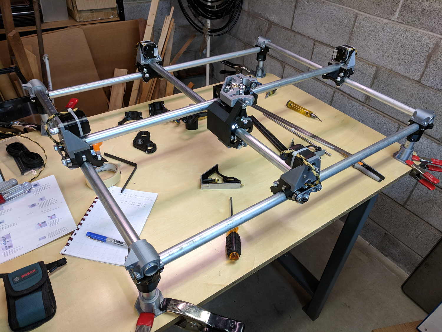
    The first trial assembly atop a new workbench went reasonably smoothly:

    Mostly Printed CNC - construction overview
    Mostly Printed CNC – construction overview

    I missed the step where you must put the high rails parallel to the X axis, which I want along the length of the table, and had to disassemble and rebuilt the frame to rotate the Middle Assembly a quarter turn clockwise. It’s always easier the second (or third) time and, if you regard the first few passes as dry runs / learning experiences, the process can be soothing, rather than annoying.

    A laser rangefinder dramatically simplifies squaring and de-skewing the rails:

    MPCNC - Laser rail measurement
    MPCNC – Laser rail measurement

    I wanted 24+ inches along the X axis and  18+ inches along the Y, so as to handle stock sizes with hard-inch measurements.The current MPCNC design adds about 11 inches to each axis outside the work area, which makes the footprint 35 × 29 (-ish) inches overall. The bench measures 30 inches front-to-back, I allowed an inch along the front to recess the moving parts, and the final frame measures 37+ × 30+ inches to the outside of all the gadgetry.

    Within that footprint, the laser says the rails are 845  × 674 mm = 33 × 26+ inch apart, giving a work area of 640 × 475 mm = 25+ × 19- inch.

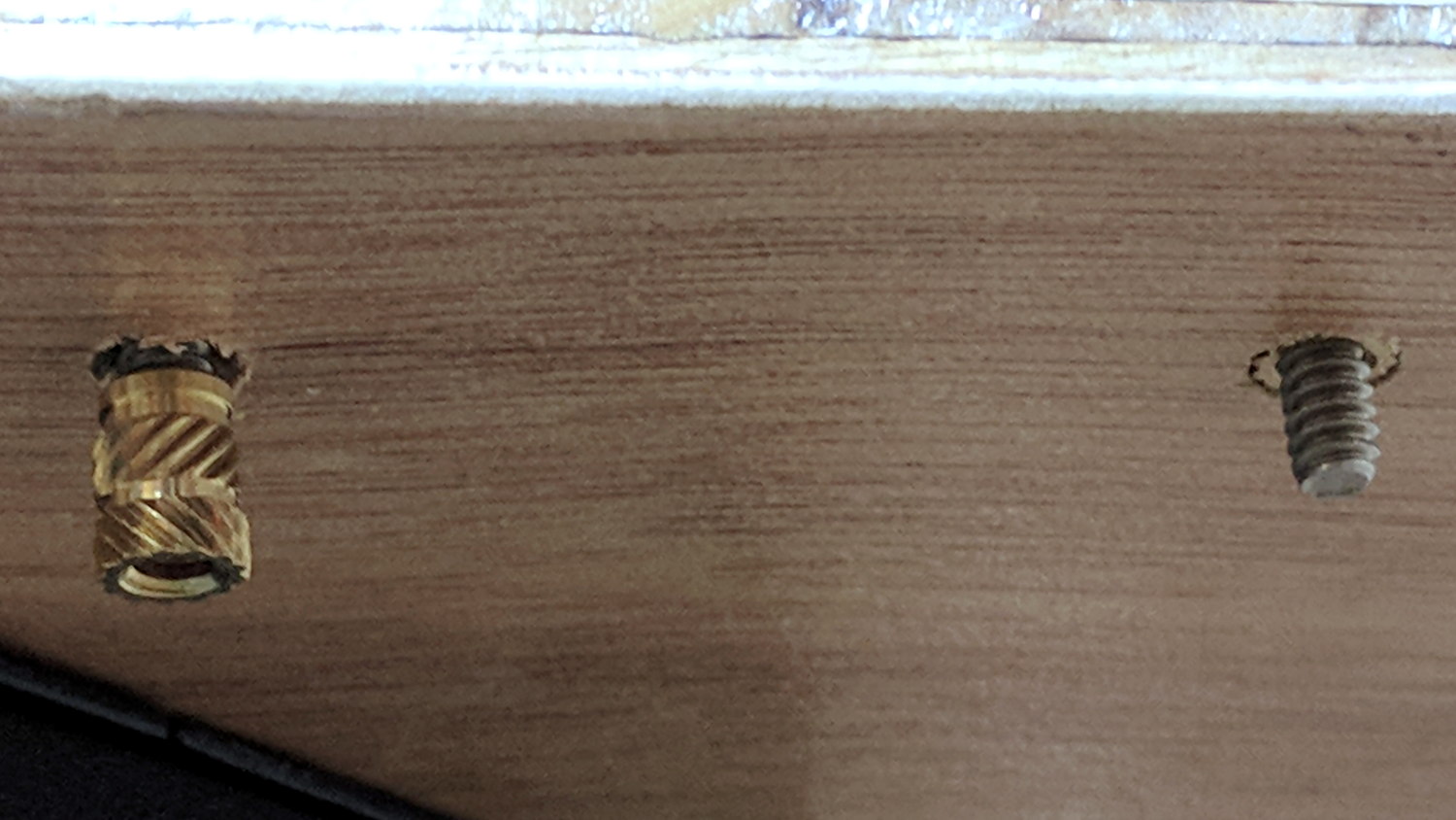
    After some careful surveying, I marked / punched / drilled holes for each mounting foot, then counterdrilled brass inserts on the bottom for that nice clean look:

    MPCNC - Table anchors
    MPCNC – Table anchors

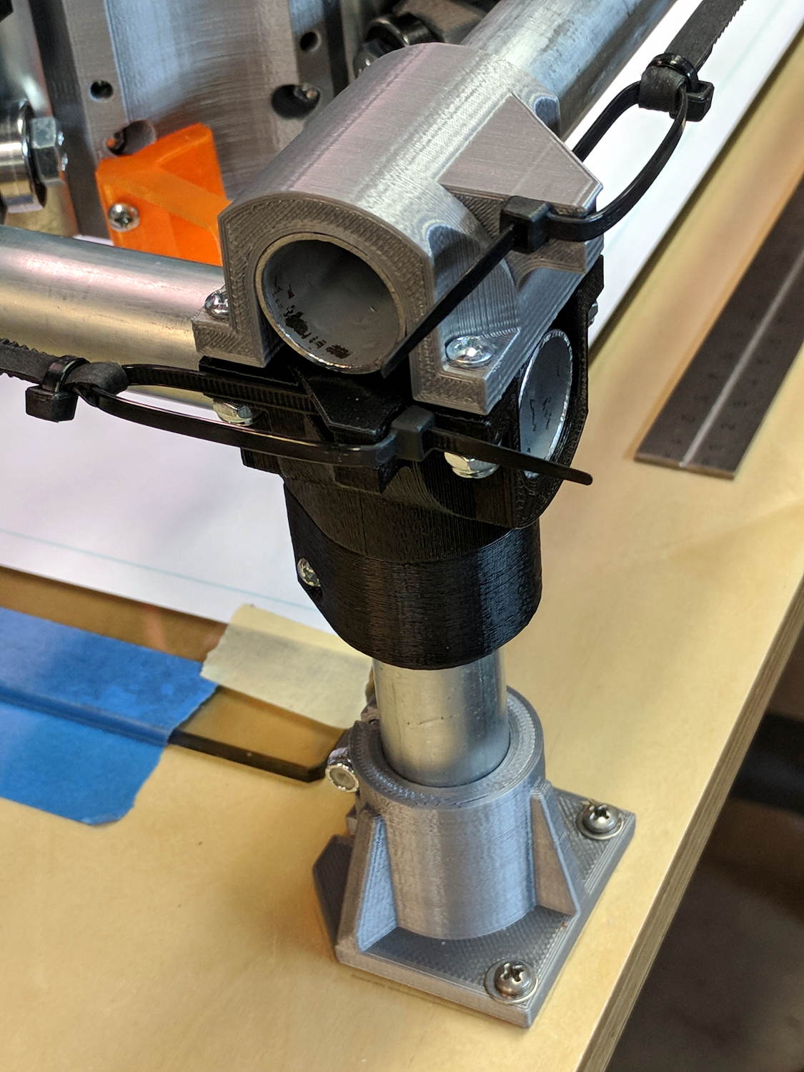
    The screws came out flush when mounted atop washers:

    MPCNC - Corner Assembly
    MPCNC – Corner Assembly

    My “careful surveying” produced a 1 mm error over the internal 1 meter diagonal, but a bit of judicious hole filing let me squash the long diagonal and stretch the short one by Just Enough to make the answer come out right, at least according to the laser rangefinder.

    Setting the rail height goes more easily with a height gauge:

    MPCNC - Rail height measurement
    MPCNC – Rail height measurement

    Stipulated: the absurdity of a height gauge on a plywood tabletop. On the other paw, the corner posts rest on that same plywood, so it actually works pretty well. I slowly pried the three lowest caps upward with the Big Screwdriver, levered on a wood block, to set all the rails to the same height as the highest one.

    The X axis rails may need mid-rail supports, although I don’t see any meaningful deflection right now.

    One could mount a T-nut atop the table inside each foot (and the center brace, as needed), with a long-ish bolt (head below the table) pushing the corner joint upward, which might be more stable than the current plastic-on-steel compression grip.

    The steppers mount on rollers gripping the rail with six bearings, plus two more bending the GT2 drive belt (not installed yet) upward to the motor drive pulley:

    MPCNC - Stepper on Roller
    MPCNC – Stepper on Roller

    I devoted a few quiet hours to threading four-wire cables through 6 mm PET braided sleeves, in hope of protecting the PVC insulation from the usual abrasion & bending stresses. I have some drag chains which may come in handy, although they seem overly klunky for the purpose.

    I’m not entirely convinced a PLA stepper mount is a Good Thing, given the warmth of steppers and PLA’s 60 °C glass transition temperature. We’ll see how it goes; obviously, one should not leave PLA parts in one’s car during a hot summer afternoon, either.

    The neatly sheathed stepper cable vanishes into the center rail held firmly by the stepper mount. An identical stepper mount grips the other end of the rail, with the motors wired in series. The conduits provide a tidy way to pass wires along the length and width of the frame.

    After you install and tension the belts, tweak the pulley location so the 6 mm belt tracks more-or-less in the middle of the 9 mm tooth width:

    MPCNC - Stepper belt alignment
    MPCNC – Stepper belt alignment

    The hulking Middle Assembly grips the X and Y cross bars:

    MPCNC - Middle Assembly
    MPCNC – Middle Assembly

    It has six printed parts, three each in two matching pairs, 24 bearings in eight triples, and plenty of 5/16 inch bolts + locknuts holding it together: all the metal bits make it weigh a lot more than you’d expect.

    The Z axis rails fit into the two pairs of three bearings facing you:

    MPCNC - Correct Mid-Assembly orientation
    MPCNC – Correct Mid-Assembly orientation

    You’ll note the correct Middle Assembly orientation, after I rearranged the frame with the high rails along the X axis. Home switches will eventually fit neatly on the untraveled rail sections near the front-left corner post.

    I built the Z using the default 12 inch rails called out by the Cut Calculator (metric version), which left an inch of the leadscrew sticking out beyond the bottom of the rails:

    MPCNC - Z leadscrew - 12 inch rails
    MPCNC – Z leadscrew – 12 inch rails

    I left the work height at the default 4 inches, which specifies a minimum 7 inch = 175 mm leadscrew. The actual leadscrew is 300 mm = 8 inch, which completely explains the situation. I’ll rebuilt the Z axis with longer rails, but this suffices for now.

    The concave silvery part joining the Z axis struts is the tool mount, to which you screw a tool holder:

    MPCNC - Pen Holder Detail
    MPCNC – Pen Holder Detail

    That’s the Official Drag Knife / Pen Holder, generally seen with a Sharpie ziptied in place, but I have Real Plotter Pens, dammit, and I’m going to use them! The holder has one hole dangling to put the pen nib below the end of the leadscrew.

    All in all, I like it …


  • RAMPS 1.4: Simulated Heater

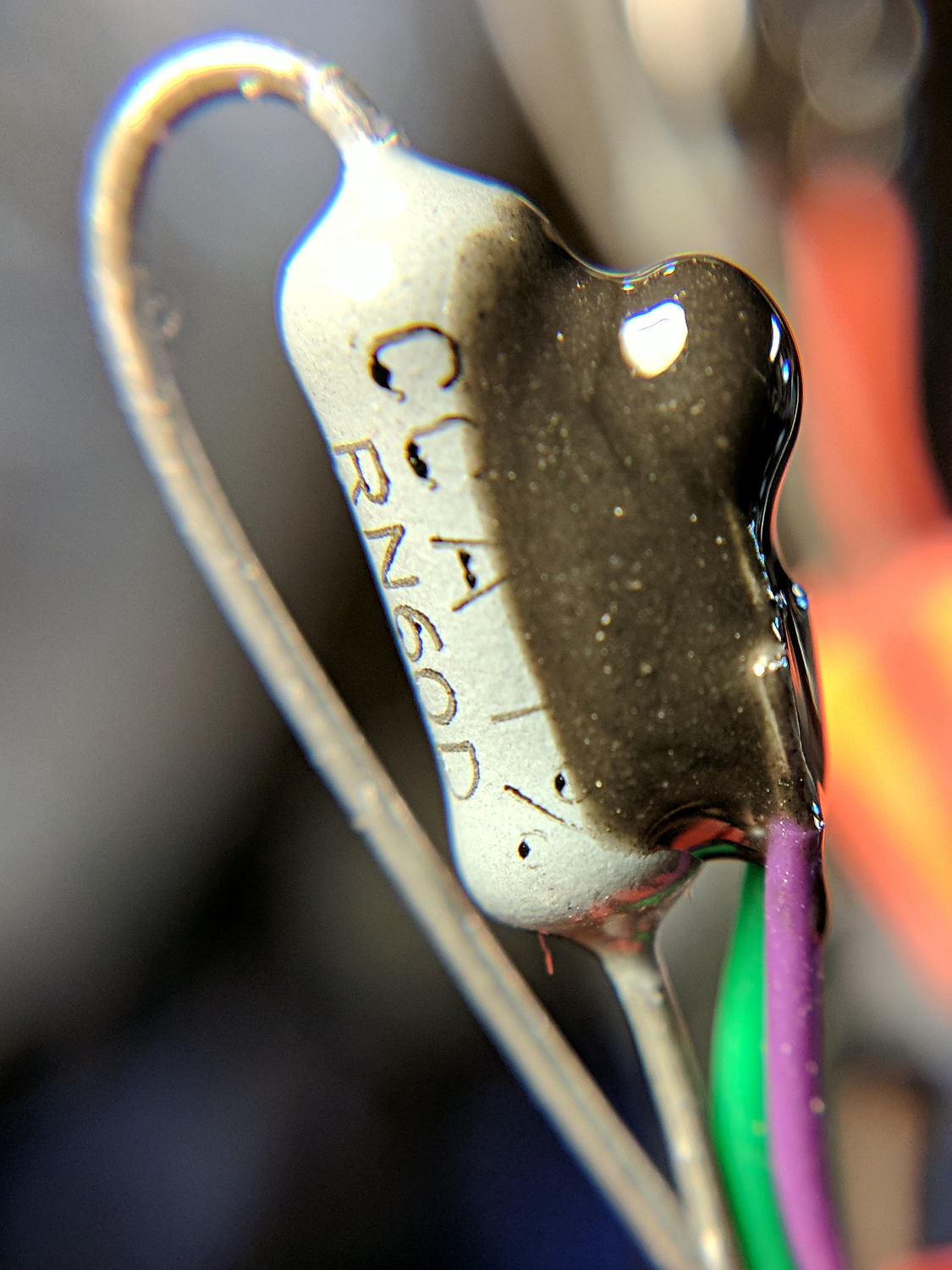
    Epoxying a 100 kΩ thermistor to a 909 Ω resistor (because I have a bunch of them) serves as a simple heater tester:

    Simulated heater - thermistor bonding
    Simulated heater – thermistor bonding

    It dissipates 450 mW, raising the temperature enough to let the PWM control kick in, but not enough to get scary hot.

    Some heatstink tubing prevents reduces the likelihood of horrible accidents involving the 20 V motor / heater power supply:

    RAMPS 1.4 - Simulated heaters
    RAMPS 1.4 – Simulated heaters

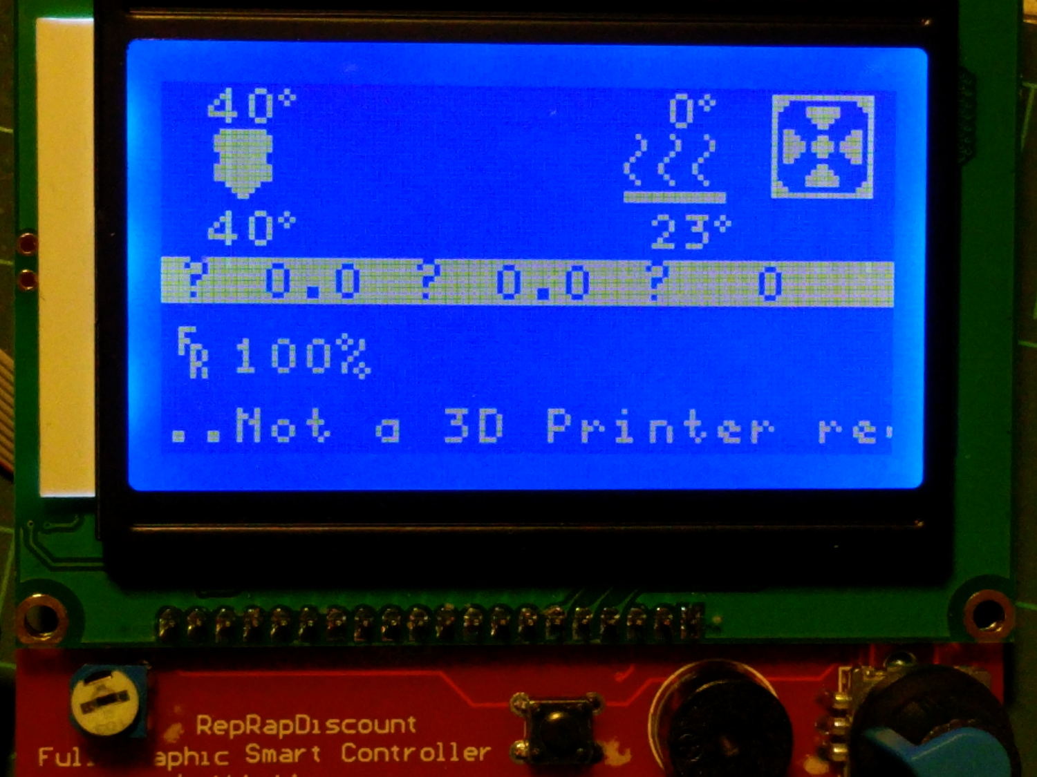
    Keeping it under 50 °C seems like a Good Idea:

    RAMPS 1.4 - Simulated heater - LCD
    RAMPS 1.4 – Simulated heater – LCD

    Not that I have a need to heat anything, but the MOSFETs work!


  • Two-Wheel Plotter

    While contemplating all the hocus-pocus and precision alignment involved in the DIY plotter project, it occurred to me you could conjure a plotter from a pair of steppers, two disks, a lifting mechanism, and not much else. The general idea resembles an Rθ plotter, with the paper glued to a turntable for the “theta” motion, but with the “radius” motion produced by pen(s) on another turntable:

    Rotary Plotter - geometry 4
    Rotary Plotter – geometry 4

    The big circle is the turntable with radius R1, which might be a touch over 4.5 inches to fit an 8.5 inch octagon cut from ordinary Letter paper. The arc with radius R2 over on the right shows the pen path from the turntable’s center to its perimeter, centered at (R1/2,-R1) for convenience.

    The grid paper represents the overall Cartesian grid containing the XY points you’d like to plot, like, for example, point Pxy in the upper right corner. The object of the game is to figure out how to rotate the turntable and pen holder to put Pxy directly under the pen at Ixy over near the right side, after which one might make a dot by lowering the pen. Drawing a continuous figure requires making very small motions between closely spaced points, using something like Bresenham’s line algorithm to generate the incremental coordinates or, for parametric curves like the SuperFormula, choosing a small parameter step size.

    After flailing around for a while, I realized this requires finding the intersections of two circles after some coordinate transformations.

    The offset between the two centers is (ΔX,ΔY) and the distance is R2 = sqrt(ΔX² + ΔY²).  The angle between the +X axis and the pen wheel is α = atan2(ΔY,ΔX), which will be negative for this layout.

    Start by transforming Pxy to polar coordinates PRθ, which produces the circle containing both Pxy and Ixy. A pen positioned at radius R from the center of the turntable will trace that circle and Ixy sits at the intersection of that circle with the pen rotating around its wheel.

    The small rectangle with sides a and b has R as its diagonal, which means a² + b² = R² and the pointy angle γ = atan a/b.

    The large triangle below that has base (R2 – a), height b, and hypotenuse R2, so (R2 – a)² + b² = R2².

    Some plug-and-chug action produces a quadratic equation that you can solve for a as shown, solve for b using the first equation, find γ from atan a/b, then subtract γ from θ to get β, the angle spearing point Ixy. You can convert Rβ back to the original grid coordinates with the usual x = R cos β and y = R sin β.

    Rotate the turntable by (θ – β) to put Pxy on the arc of the pen at Ixy.

    The angle δ lies between the center-to-center line and Ixy. Knowing all the sides of that triangle, find δ = arccos (R2 – a) / R2 and turn the pen wheel by δ to put the pen at Ixy.

    Lower the pen to make a dot.

    Done!

    Some marginal thinking …

    I’m sure there’s a fancy way to do this with, surely, matrices or quaternions, but I can handle trig.

    You could drive the steppers with a Marlin / RAMPS controller mapping between angles and linear G-Code coordinates, perhaps by choosing suitable steps-per-unit values to make the degrees (or some convenient decimal multiple / fraction thereof) correspond directly to linear distances.

    You could generate points from an equation in, say, Python on a Raspberry Pi, apply all the transformations, convert the angles to G-Code, and fire them at a Marlin controller over USB.

    Applying 16:1 microstepping to a stock 200 step/rev motor gives 0.113°/step, so at a 5 inch radius each step covers 0.01 inch. However, not all microsteps are moved equally and I expect the absolute per-step accuracy would be somewhere between OK and marginal. Most likely, given the application, even marginal accuracy wouldn’t matter in the least.

    The pen wheel uses only 60-ish degrees of the motor’s rotation, but you could mount four-ish pens around a complete wheel, apply suitable pen lift-and-lower action and get multicolor plots.

    You could gear down the steppers to get more steps per turntable revolution and way more steps per pen arc, perhaps using cheap & readily available RepRap printer GT2 pulleys / belts / shafts / bearings from the usual eBay sellers. A 16 tooth motor pulley driving a 60 tooth turntable pulley would improve the resolution by a factor of 3.75: more microsteps per commanded motion should make the actual motion come out better.

    Tucking the paper atop the turntable and under the pen wheel could be a challenge. Perhaps mounting the whole pen assembly on a tilting plate would help?

    Make all the workings visible FTW!

    Some doodles leading up to the top diagram, complete with Bad Ideas and goofs …

    Centering the pen wheel at a corner makes R2 = R1 * sqrt(2), which seems attractive, but seems overly large in retrospect:

    Rotary Plotter - geometry 1
    Rotary Plotter – geometry 1

    Centering the pen wheel at (-R1,R1/2) with a radius of R1 obviously doesn’t work out, because the arc doesn’t reach the turntable pivot, so you can’t draw anything close to the center. At least I got to work out some step sizes.

    A first attempt at coordinate transformation went nowhere:

    Rotary Plotter - geometry 2
    Rotary Plotter – geometry 2

    After perusing the geometric / triangle solution, this came closer:

    Rotary Plotter - geometry 3
    Rotary Plotter – geometry 3
  • RAMPS 1.4: Configuration for Generic Motor Control

    Configuring the knockoff RAMPS 1.4 board went reasonably smoothly:

    RAMPS 1.4 - First Light
    RAMPS 1.4 – First Light

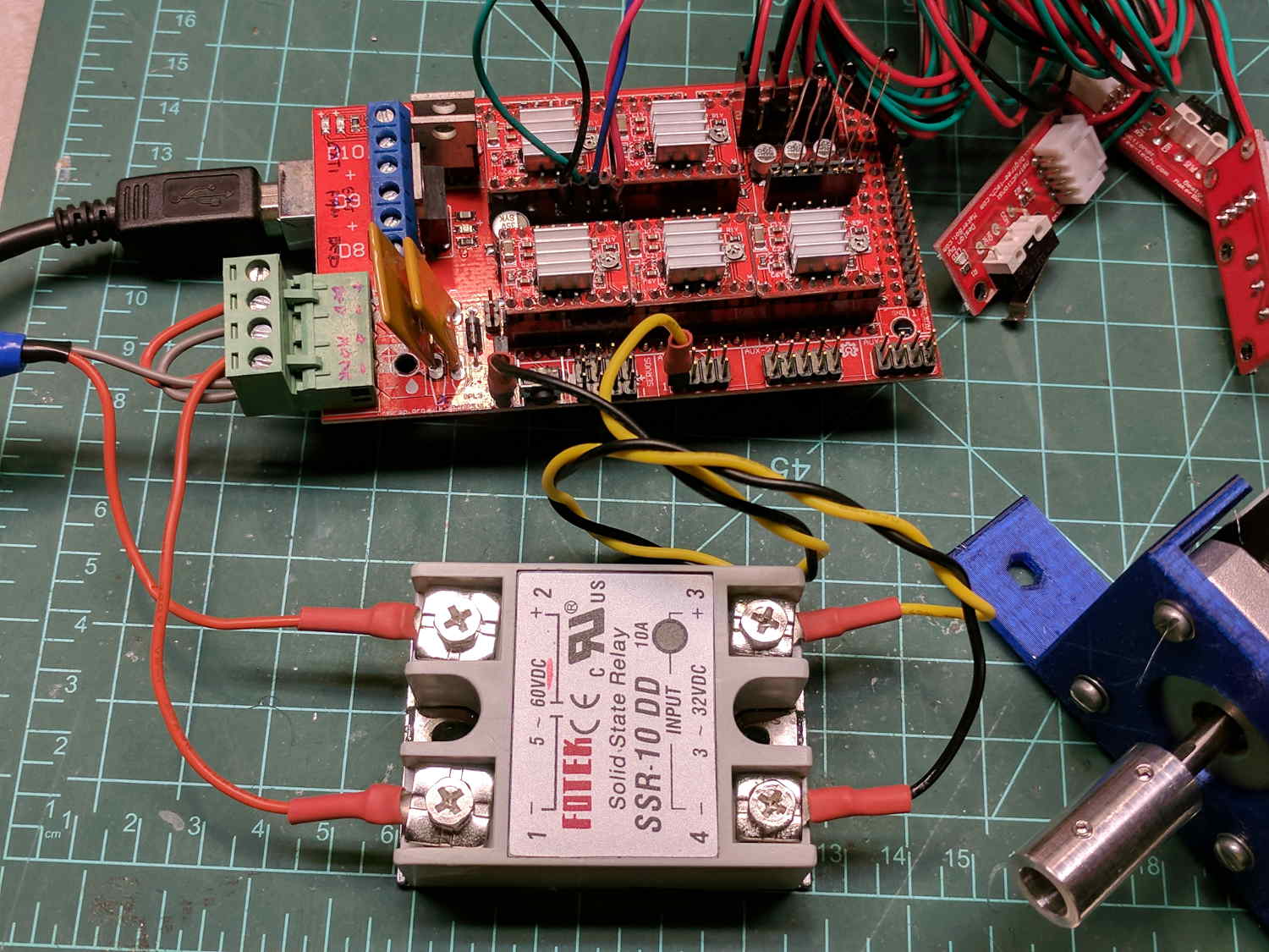
    The DC (n.b., not an AC) solid state relay in the foreground switches the 20 V laptop supply brick to the RAMPS shield atop the knockoff Arduino Mega 2560, controlled by the PS_ON pin (black wire), with +5 V from a pin in the AUX header (yellow wire). The SSR includes a ballast resistor limiting the current to 12 mA, with an inconspicuous red LED behind the black dot showing when the output is turned on.

    Because it’s a DC SSR, polarity matters: the supply goes to the + terminal, the RAMPS power inputs to the – terminal.

    I haven’t applied much of a load to to the SSR, but it works as expected. Define POWER_SUPPLY 1 and PS_DEFAULT_OFF so the boards starts up with the SSR turned off, then use M80 / M81 to turn it on / off as needed.

    Remove D1 on the RAMPS board to isolate the Mega power from the +20 V supply. Stuffed as shown, the Mega draws 70 mA from the USB port, although an external 8 V (-ish) supply is always a good idea.

    The stepper is a random NEMA 17 from the heap in a mount intended for a DIY plotter. I adjusted the tiny trimpots on all the boards for 400 mA peak = 250 mA RMS into the windings, after finding 250 mApk didn’t produce nearly enough mojo, even for a demonstration:

    X Axis Stepper Drive
    X Axis Stepper Drive

    Just to get it running, I used DEFAULT_AXIS_STEPS_PER_UNIT = 100 step/mm, MAX_FEEDRATE 100 mm/s, and (for lack of anything better)
    DEFAULT_*_ACCELERATION 1000. Those all depend the torque produced by the motor current, which is still way too low.

    The endstops require X_???_ENDSTOP_INVERTING true.

    I set the ?_BED_SIZE parameters to a generous 2000, with ?_MIN_POS equal to -SIZE/2 to put the origin in the middle where I prefer it, with a similar setting for the Z axis. Obviously, those numbers don’t correspond to any physical reality.

    Three little 100 kΩ thermistors sprout from their header and produce reasonable temperatures, although (being cheap eBay parts) they may not match the Type 4 curve. I don’t have any heaters connected. All the over / under temperature lockouts are disabled, because I don’t care right now.

    The G-Code parser wants uppercase command letters, which means I get to press the Caps Lock key for the first time in nearly forever!

    The header along the right edge of the board connects to the LCD control board, which is another story.

    The diffs for the Configuration.h and Configuration_adv.h files as a GitHub Gist:

    77c77
    < #define STRING_CONFIG_H_AUTHOR "(none, default config)" // Who made the changes.
    —
    > #define STRING_CONFIG_H_AUTHOR "(Ed Nisley – KE4ZNU)" // Who made the changes.
    113c113
    < #define BAUDRATE 250000
    —
    > #define BAUDRATE 115200
    126c126
    < //#define CUSTOM_MACHINE_NAME "3D Printer"
    —
    > #define CUSTOM_MACHINE_NAME "Not a 3D Printer"
    130c130
    < //#define MACHINE_UUID "00000000-0000-0000-0000-000000000000"
    —
    > #define MACHINE_UUID "89647f7b-2575-4809-bc90-5396f4376e02"
    225c225
    < #define POWER_SUPPLY 0
    —
    > #define POWER_SUPPLY 1
    230c230
    < //#define PS_DEFAULT_OFF
    —
    > #define PS_DEFAULT_OFF
    285c285
    < #define TEMP_SENSOR_0 1
    —
    > #define TEMP_SENSOR_0 4
    290c290
    < #define TEMP_SENSOR_BED 0
    —
    > #define TEMP_SENSOR_BED 4
    304c304
    < #define TEMP_WINDOW 1 // (degC) Window around target to start the residency timer x degC early.
    —
    > #define TEMP_WINDOW 2 // (degC) Window around target to start the residency timer x degC early.
    309c309
    < #define TEMP_BED_WINDOW 1 // (degC) Window around target to start the residency timer x degC early.
    —
    > #define TEMP_BED_WINDOW 2 // (degC) Window around target to start the residency timer x degC early.
    324,325c324,325
    < #define HEATER_0_MAXTEMP 275
    < #define HEATER_1_MAXTEMP 275
    —
    > #define HEATER_0_MAXTEMP 75
    > #define HEATER_1_MAXTEMP 75
    329c329
    < #define BED_MAXTEMP 150
    —
    > #define BED_MAXTEMP 75
    417,418c417,418
    < #define PREVENT_COLD_EXTRUSION
    < #define EXTRUDE_MINTEMP 170
    —
    > //#define PREVENT_COLD_EXTRUSION
    > #define EXTRUDE_MINTEMP 50
    422c422
    < #define PREVENT_LENGTHY_EXTRUDE
    —
    > //#define PREVENT_LENGTHY_EXTRUDE
    441,442c441,442
    < #define THERMAL_PROTECTION_HOTENDS // Enable thermal protection for all extruders
    < #define THERMAL_PROTECTION_BED // Enable thermal protection for the heated bed
    —
    > //#define THERMAL_PROTECTION_HOTENDS // Enable thermal protection for all extruders
    > //#define THERMAL_PROTECTION_BED // Enable thermal protection for the heated bed
    476c476
    < #define ENDSTOPPULLUPS // Comment this out (using // at the start of the line) to disable the endstop pullup resistors
    —
    > //#define ENDSTOPPULLUPS // Comment this out (using // at the start of the line) to disable the endstop pullup resistors
    490,495c490,495
    < #define X_MIN_ENDSTOP_INVERTING false // set to true to invert the logic of the endstop.
    < #define Y_MIN_ENDSTOP_INVERTING false // set to true to invert the logic of the endstop.
    < #define Z_MIN_ENDSTOP_INVERTING false // set to true to invert the logic of the endstop.
    < #define X_MAX_ENDSTOP_INVERTING false // set to true to invert the logic of the endstop.
    < #define Y_MAX_ENDSTOP_INVERTING false // set to true to invert the logic of the endstop.
    < #define Z_MAX_ENDSTOP_INVERTING false // set to true to invert the logic of the endstop.
    —
    > #define X_MIN_ENDSTOP_INVERTING true // set to true to invert the logic of the endstop.
    > #define Y_MIN_ENDSTOP_INVERTING true // set to true to invert the logic of the endstop.
    > #define Z_MIN_ENDSTOP_INVERTING true // set to true to invert the logic of the endstop.
    > #define X_MAX_ENDSTOP_INVERTING true // set to true to invert the logic of the endstop.
    > #define Y_MAX_ENDSTOP_INVERTING true // set to true to invert the logic of the endstop.
    > #define Z_MAX_ENDSTOP_INVERTING true // set to true to invert the logic of the endstop.
    527c527
    < #define DEFAULT_AXIS_STEPS_PER_UNIT { 80, 80, 4000, 500 }
    —
    > #define DEFAULT_AXIS_STEPS_PER_UNIT { 100, 100, 100, 100 }
    534c534
    < #define DEFAULT_MAX_FEEDRATE { 300, 300, 5, 25 }
    —
    > #define DEFAULT_MAX_FEEDRATE { 100, 100, 100, 100 }
    542c542
    < #define DEFAULT_MAX_ACCELERATION { 3000, 3000, 100, 10000 }
    —
    > #define DEFAULT_MAX_ACCELERATION { 1000, 1000, 1000, 1000 }
    552,554c552,554
    < #define DEFAULT_ACCELERATION 3000 // X, Y, Z and E acceleration for printing moves
    < #define DEFAULT_RETRACT_ACCELERATION 3000 // E acceleration for retracts
    < #define DEFAULT_TRAVEL_ACCELERATION 3000 // X, Y, Z acceleration for travel (non printing) moves
    —
    > #define DEFAULT_ACCELERATION 1000 // X, Y, Z and E acceleration for printing moves
    > #define DEFAULT_RETRACT_ACCELERATION 1000 // E acceleration for retracts
    > #define DEFAULT_TRAVEL_ACCELERATION 1000 // X, Y, Z acceleration for travel (non printing) moves
    566,567c566,567
    < #define DEFAULT_ZJERK 0.4
    < #define DEFAULT_EJERK 5.0
    —
    > #define DEFAULT_ZJERK 20.0
    > #define DEFAULT_EJERK 20.0
    744c744
    < #define INVERT_X_DIR false
    —
    > #define INVERT_X_DIR true
    746c746
    < #define INVERT_Z_DIR false
    —
    > #define INVERT_Z_DIR true
    774,775c774,775
    < #define X_BED_SIZE 200
    < #define Y_BED_SIZE 200
    —
    > #define X_BED_SIZE 2000
    > #define Y_BED_SIZE 2000
    778,783c778,783
    < #define X_MIN_POS 0
    < #define Y_MIN_POS 0
    < #define Z_MIN_POS 0
    < #define X_MAX_POS X_BED_SIZE
    < #define Y_MAX_POS Y_BED_SIZE
    < #define Z_MAX_POS 200
    —
    > #define X_MIN_POS -X_BED_SIZE/2
    > #define Y_MIN_POS -Y_BED_SIZE/2
    > #define Z_MIN_POS -1000
    > #define X_MAX_POS X_BED_SIZE/2
    > #define Y_MAX_POS Y_BED_SIZE/2
    > #define Z_MAX_POS 1000
    1013c1013
    < //#define EEPROM_SETTINGS // Enable for M500 and M501 commands
    —
    > #define EEPROM_SETTINGS // Enable for M500 and M501 commands
    1023c1023
    < #define HOST_KEEPALIVE_FEATURE // Disable this if your host doesn't like keepalive messages
    —
    > //#define HOST_KEEPALIVE_FEATURE // Disable this if your host doesn't like keepalive messages
    1046,1047c1046,1047
    < #define PREHEAT_1_TEMP_BED 70
    < #define PREHEAT_1_FAN_SPEED 0 // Value from 0 to 255
    —
    > #define PREHEAT_1_TEMP_BED 60
    > #define PREHEAT_1_FAN_SPEED 255 // Value from 0 to 255
    1050,1051c1050,1051
    < #define PREHEAT_2_TEMP_BED 110
    < #define PREHEAT_2_FAN_SPEED 0 // Value from 0 to 255
    —
    > #define PREHEAT_2_TEMP_BED 90
    > #define PREHEAT_2_FAN_SPEED 255 // Value from 0 to 255
    1275c1275
    < //#define REVERSE_ENCODER_DIRECTION
    —
    > #define REVERSE_ENCODER_DIRECTION
    1290c1290
    < //#define INDIVIDUAL_AXIS_HOMING_MENU
    —
    > #define INDIVIDUAL_AXIS_HOMING_MENU
    1307,1308c1307,1308
    < //#define LCD_FEEDBACK_FREQUENCY_DURATION_MS 100
    < //#define LCD_FEEDBACK_FREQUENCY_HZ 1000
    —
    > #define LCD_FEEDBACK_FREQUENCY_DURATION_MS 50
    > #define LCD_FEEDBACK_FREQUENCY_HZ 700
    1379c1379
    < //#define REPRAP_DISCOUNT_FULL_GRAPHIC_SMART_CONTROLLER
    —
    > #define REPRAP_DISCOUNT_FULL_GRAPHIC_SMART_CONTROLLER
    65,66c65,66
    < #define THERMAL_PROTECTION_PERIOD 40 // Seconds
    < #define THERMAL_PROTECTION_HYSTERESIS 4 // Degrees Celsius
    —
    > #define THERMAL_PROTECTION_PERIOD 100 // Seconds
    > #define THERMAL_PROTECTION_HYSTERESIS 5 // Degrees Celsius
    77c77
    < #define WATCH_TEMP_PERIOD 20 // Seconds
    —
    > #define WATCH_TEMP_PERIOD 60 // Seconds
    85c85
    < #define THERMAL_PROTECTION_BED_PERIOD 20 // Seconds
    —
    > #define THERMAL_PROTECTION_BED_PERIOD 120 // Seconds
    97c97
    < #define WATCH_BED_TEMP_PERIOD 60 // Seconds
    —
    > #define WATCH_BED_TEMP_PERIOD 120 // Seconds
    225c225
    < *
    —
    > *
    352c352
    < #define HOMING_BUMP_DIVISOR {2, 2, 4} // Re-Bump Speed Divisor (Divides the Homing Feedrate)
    —
    > #define HOMING_BUMP_DIVISOR {4, 4, 4} // Re-Bump Speed Divisor (Divides the Homing Feedrate)
    374c374
    < #define DEFAULT_STEPPER_DEACTIVE_TIME 120
    —
    > #define DEFAULT_STEPPER_DEACTIVE_TIME 0
    458c458
    < //#define LCD_INFO_MENU
    —
    > #define LCD_INFO_MENU
    461c461
    < //#define STATUS_MESSAGE_SCROLLING
    —
    > #define STATUS_MESSAGE_SCROLLING
    464c464
    < //#define LCD_DECIMAL_SMALL_XY
    —
    > #define LCD_DECIMAL_SMALL_XY
    467c467
    < //#define LCD_TIMEOUT_TO_STATUS 15000
    —
    > #define LCD_TIMEOUT_TO_STATUS 10000
    562c562
    < #define XYZ_HOLLOW_FRAME
    —
    > //#define XYZ_HOLLOW_FRAME
    565c565
    < #define MENU_HOLLOW_FRAME
    —
    > //#define MENU_HOLLOW_FRAME
    573c573
    < //#define USE_SMALL_INFOFONT
    —
    > #define USE_SMALL_INFOFONT
    752c752
    < #define TX_BUFFER_SIZE 0
    —
    > #define TX_BUFFER_SIZE 128
  • Plotter Grit Wheel Bushings

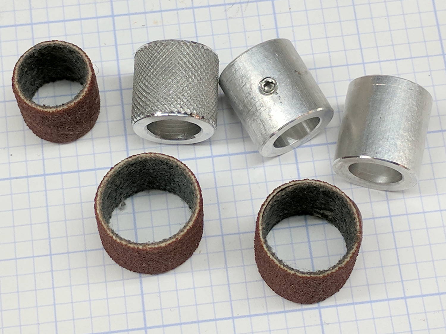
    As part of recommissioning the lathe tailstock, I made some bushings to adapt Dremel sanding drums bands to an 8 mm shaft (in imitation of the grit drive wheels on the HP plotter):

    Plotter Y bushing - samples
    Plotter Y bushing – samples

    They’re not all the same because the lad who’s building the plotter got to turn out his own bushings. We think the knurled version, with a setscrew to lock it on the shaft, will work better than adhesive-bonding the drum to the bushing.

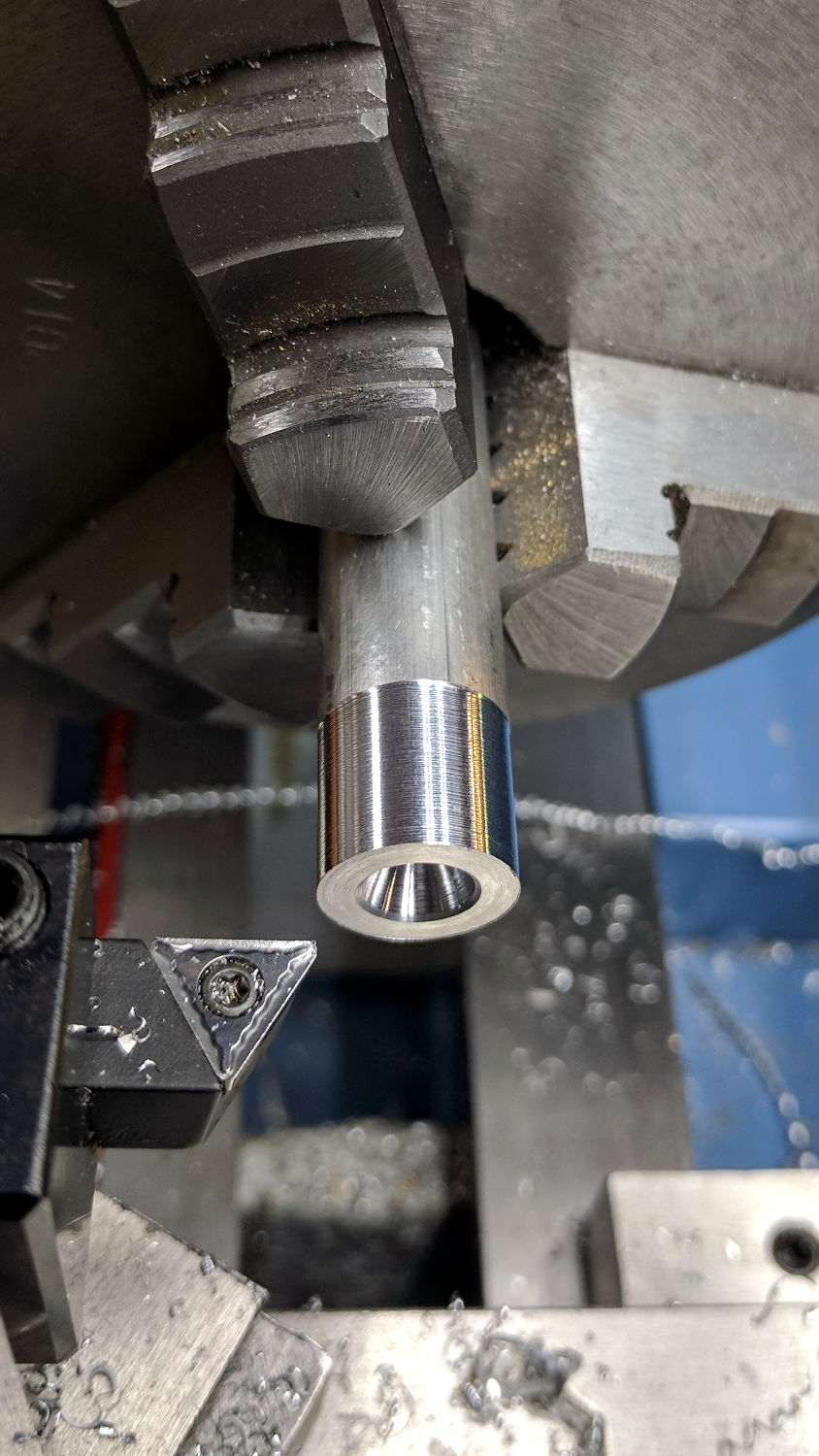
    The overall process starts with a rough 1/2 inch aluminum rod. Skim-cut to get a concentric surface and face the end smooth:

    Plotter Y bushing - facing
    Plotter Y bushing – facing

    Then knurl it:

    Plotter Y bushing - knurling
    Plotter Y bushing – knurling

    The skim cut makes the aluminum rod a loose fit inside the sanding band, but the knurling enlarges the diameter enough to make it a firm press fit and I think it’ll have enough traction to stay in place.

    FWIW, the wheels in the LittleMachineShop knurling tool seem pretty bad: the central holes aren’t quite concentric with the cutting edge, the bores are a loose fit on the mounting screws, the wheels are much narrower than the slots they ride in, so they wobble uncontrollably. It’s not a fatal flaw, but they definitely produce a sub-par knurl.

    Face off the front, cut the knurling down at each end, then part it off:

    Plotter Y bushing - cutoff
    Plotter Y bushing – cutoff

    Clamp it in the Sherline mill, laser-spot the edges, set the origin in the middle, and center drill:

    Plotter Y bushing - center drill
    Plotter Y bushing – center drill

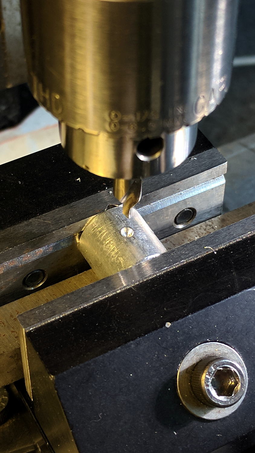
    Drill and tap for a teeny M3 setscrew:

    Plotter Y bushing - tapping
    Plotter Y bushing – tapping

    Clean out the chips, debur the hole, install the setscrew, and you’re half-done: do it again to get the second drive roller!


  • NEMA17 Motor and Bearing Mounts

    As part of coaching a student (and his father!) on their incredibly ambitious build-a-plotter-from-scratch project, I suggested stealing using HP’s grit-wheel paper drive, rather than fiddling with guide rods to move either the pen carrier or the entire paper platform. Dremel sanding drums seem about the right size and they had an 8 mm shaft harvested from a defunct printer, so a pair of mounts moves the project along:

    NEMA17 and Bearing Mounts - Slic3r preview
    NEMA17 and Bearing Mounts – Slic3r preview

    The motor mount code is a hack job from my old NEMA17 mount and the code has a lot not to like. The bearing mount puts the bearing on the proper centerline using brute force copypasta and depends on friction to hold it in place. The two models should be integrated into the same file, the shaft centerline shouldn’t involve the printed thread width, and blah blah blah:

    NEMA17 motor and bearing mounts
    NEMA17 motor and bearing mounts

    I had him turn the shaft adapter from an aluminum rod in the mini-lathe: he’s hooked.

    The OpenSCAD source code as a GitHub Gist:

    // Ball bearing mount
    // Ed Nisley KE4ZNU 2017-10-09
    //– Extrusion parameters
    ThreadThick = 0.20;
    ThreadWidth = 0.40;
    HoleWindage = 0.2; // enlarge hole dia by this amount
    function IntegerMultiple(Size,Unit) = Unit * ceil(Size / Unit);
    Protrusion = 0.1; // make holes look good and joints intersect properly
    //– Useful sizes
    inch = 25.4;
    Tap10_32 = 0.159 * inch;
    Clear10_32 = 0.190 * inch;
    Head10_32 = 0.373 * inch;
    Head10_32Thick = 0.110 * inch;
    Nut10_32Dia = 0.433 * inch;
    Nut10_32Thick = 0.130 * inch;
    // Bearing sizes
    ID = 0;
    OD = 1;
    LENGTH = 2;
    Bearing = [8.0,22.0,7.0];
    ShaftHeight = IntegerMultiple(25.2,ThreadWidth); // arbitrary or copied from motor mount
    WallThick = 3.0;
    //– Mount Sizes
    MountSize = Bearing[OD] + 2*WallThick;
    BaseThick = max(WallThick,ShaftHeight – MountSize/2); // baseplate
    StandBoltHead = IntegerMultiple(Head10_32,2); // bolt head rounded up
    StandBoltClear = 1.25 * StandBoltHead;
    StandBoltOC = IntegerMultiple(MountSize + StandBoltClear,2);
    StandLength = StandBoltOC + StandBoltClear;
    StandThick = StandBoltClear + WallThick;
    StandHeight = MountSize + BaseThick;
    Cutout = (StandLength – MountSize)/2;
    echo(str("Stand Base: ",StandLength," x ",StandThick," x ",BaseThick));
    echo(str("Stand Bolt OC: ",StandBoltOC));
    echo(str("Shaft Height:",ShaftHeight));
    //———————-
    // Useful routines
    module PolyCyl(Dia,Height,ForceSides=0) { // based on nophead's polyholes
    Sides = (ForceSides != 0) ? ForceSides : (ceil(Dia) + 2);
    FixDia = Dia / cos(180/Sides);
    cylinder(r=(FixDia + HoleWindage)/2,
    h=Height,
    $fn=Sides);
    }
    //———————-
    // Put it together
    module BearingMount() {
    difference() {
    translate([BaseThick/2,0,StandThick/2])
    cube([StandHeight,StandLength,StandThick],center=true);
    translate([0,0,-Protrusion])
    PolyCyl(Bearing[OD],(StandThick + 2*Protrusion));
    for (j=[-1,1]) // cutouts over bolts
    translate([-(StandHeight/2 – ShaftHeight + WallThick),
    j*(StandLength/2 – Cutout/2 + Protrusion/2),
    (WallThick + StandThick/2)])
    cube([StandHeight,
    Cutout + Protrusion,
    StandThick],center=true);
    for (j=[-1,1]) // stand bolt holes – base
    translate([(MountSize/2 – Protrusion),
    j*StandBoltOC/2,
    WallThick + StandBoltClear/2])
    rotate([0,90,0])
    rotate(180/6)
    PolyCyl(Clear10_32,BaseThick + 2*Protrusion,6);
    for (j=[-1,1]) // stand bolt holes – back
    translate([0,j*StandBoltOC/2,-Protrusion])
    rotate(180/6)
    PolyCyl(Clear10_32,StandThick + 2*Protrusion,6);
    translate([0,-(MountSize/2 – ThreadWidth/2),(StandThick – WallThick)/2 + WallThick])
    rotate([90,180,0])
    linear_extrude(ThreadWidth,convexity=10)
    text(text=str(ShaftHeight),size=6,spacing=1.20,font="Arial",halign="center",valign="center");
    }
    }
    //———————-
    // Build it
    BearingMount();
    // NEMA 17 stepper mount
    // Ed Nisley KE4ZNU August 2011
    // Tweaked & thinned 2017-10-09
    //– Extrusion parameters
    ThreadThick = 0.25;
    ThreadWidth = 0.4;
    HoleWindage = 0.3; // enlarge hole dia by this amount
    function IntegerMultiple(Size,Unit) = Unit * ceil(Size / Unit);
    Protrusion = 0.1; // make holes look good and joints intersect properly
    //– Useful sizes
    inch = 25.4;
    Tap10_32 = 0.159 * inch;
    Clear10_32 = 0.190 * inch;
    Head10_32 = 0.373 * inch;
    Head10_32Thick = 0.110 * inch;
    Nut10_32Dia = 0.433 * inch;
    Nut10_32Thick = 0.130 * inch;
    NEMA17_ShaftDia = 5.0;
    NEMA17_ShaftLength = 24.0;
    NEMA17_PilotDia = 0.866 * inch;
    NEMA17_PilotLength = 0.080 * inch;
    NEMA17_BCD = 1.725 * inch;
    NEMA17_BoltDia = 3.5;
    NEMA17_BoltOC = 1.220 * inch;
    //– Mount Sizes
    MountWidth = IntegerMultiple(NEMA17_BCD,ThreadWidth); // use BCD for motor clearance
    MountThick = IntegerMultiple(4.0,ThreadThick); // for stiffness
    MountBoltDia = 3.0;
    StandThick = 3.0; // baseplate
    StrutThick = IntegerMultiple(3.0,ThreadWidth); // sides holding motor mount
    UprightLength = MountWidth + 2*StrutThick;
    StandBoltHead = IntegerMultiple(Head10_32,5); // bolt head rounded up
    StandBoltOC = IntegerMultiple(UprightLength + 2*StandBoltHead,5);
    StandLength = StandBoltOC + 2*StandBoltHead;
    StandWidth = 2*StandBoltHead;
    StandBoltClear = (StandLength – UprightLength)/2; // flat around bolt head
    MotorRecess = StandWidth – MountThick;
    ShaftHeight = IntegerMultiple(StandThick + MountWidth/2,ThreadWidth);
    echo(str("Stand Base: ",StandLength," x ",StandWidth," x ",StandThick));
    echo(str("Stand Bolt OC: ",StandBoltOC));
    echo(str("Shaft Height:",ShaftHeight));
    echo(str("Strut Thick: ",StrutThick));
    //———————-
    // Useful routines
    module PolyCyl(Dia,Height,ForceSides=0) { // based on nophead's polyholes
    Sides = (ForceSides != 0) ? ForceSides : (ceil(Dia) + 2);
    FixDia = Dia / cos(180/Sides);
    cylinder(r=(FixDia + HoleWindage)/2,
    h=Height,
    $fn=Sides);
    }
    //———————-
    // Model
    module MotorMount() {
    difference() {
    translate([StandThick/2,0,StandWidth/2])
    cube([(MountWidth + StandThick),StandLength,StandWidth],center=true);
    translate([-Protrusion/2,0,StandWidth – (MotorRecess – Protrusion)/2])
    cube([(MountWidth + Protrusion),MountWidth,(MotorRecess + Protrusion)],center=true);
    translate([0,0,-Protrusion]) // pilot hole
    PolyCyl(NEMA17_PilotDia,(MountThick + 2*Protrusion));
    for (i=[-1,1]) // motor bolt holes
    for (j=[-1,1])
    translate([i*NEMA17_BoltOC/2,j*NEMA17_BoltOC/2,-Protrusion])
    PolyCyl(MountBoltDia,(MountThick + 2*Protrusion),6);
    for (j=[-1,1]) // cutouts over bolts
    translate([-Protrusion/2,
    j*((StandLength – StandBoltClear)/2 + Protrusion/2),
    StandWidth/2])
    cube([(MountWidth + Protrusion),
    (StandBoltClear + Protrusion),
    (StandWidth + 2*Protrusion)],center=true);
    for (j=[-1,1]) // stand bolt holes
    translate([(MountWidth/2 – Protrusion),j*StandBoltOC/2,StandWidth/2])
    rotate([0,90,0])
    rotate(180/6)
    PolyCyl(Clear10_32,StandThick + 2*Protrusion,6);
    translate([0,-(UprightLength/2 – ThreadWidth/2),StandWidth/2])
    rotate([90,180,0])
    linear_extrude(ThreadWidth,convexity=10)
    text(text=str(ShaftHeight),size=6,spacing=1.20,font="Arial",halign="center",valign="center");
    }
    }
    //———————-
    // Build it
    MotorMount();