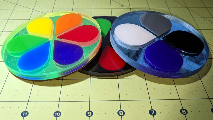
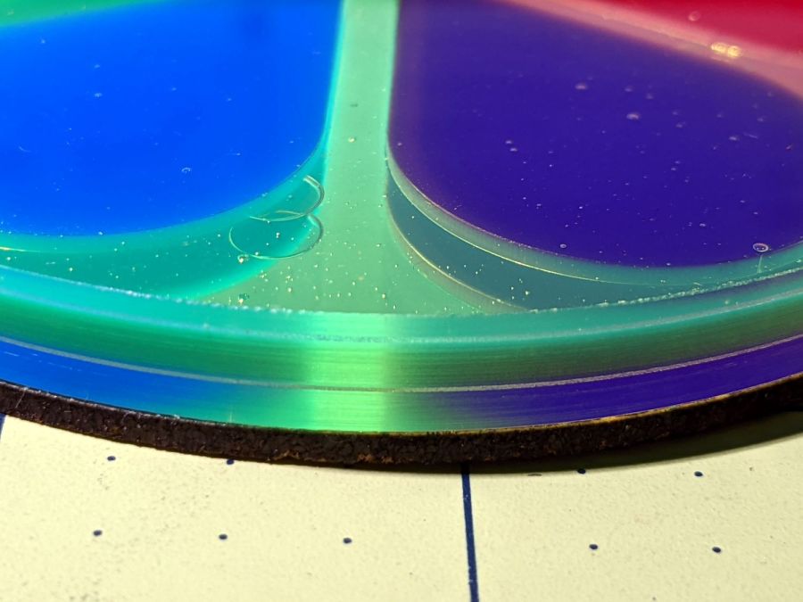
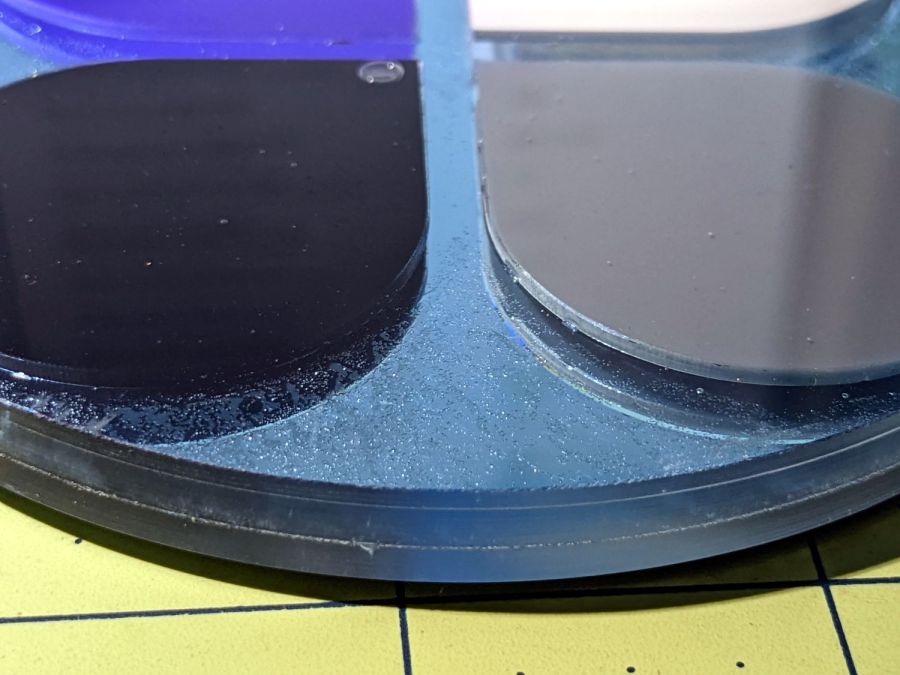
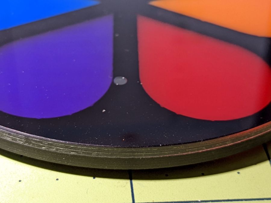
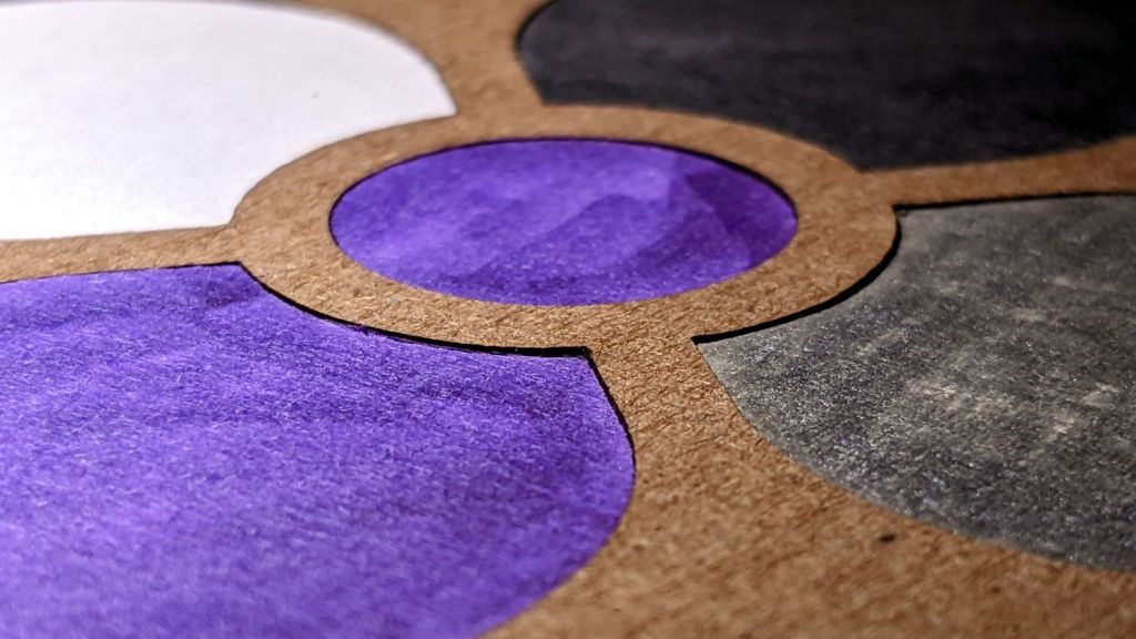
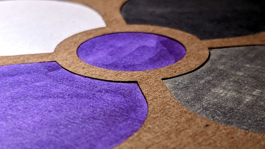
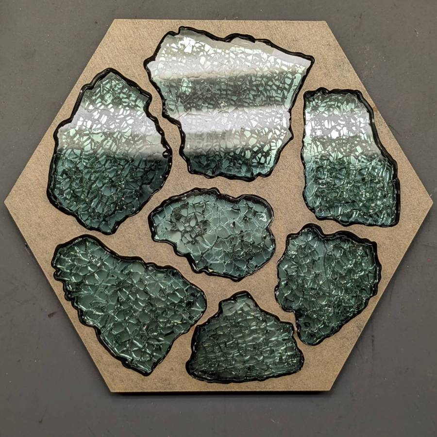
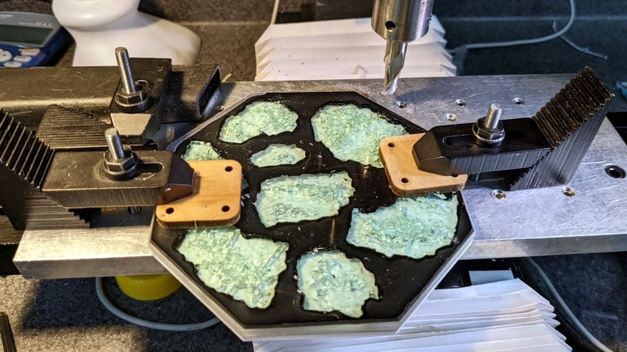
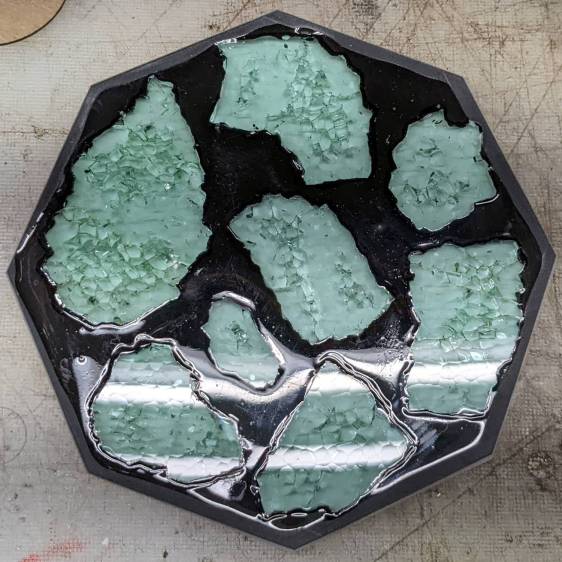
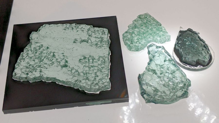
A few more attempts at layered paper construction, done with plain white Art Paper of various vintages:

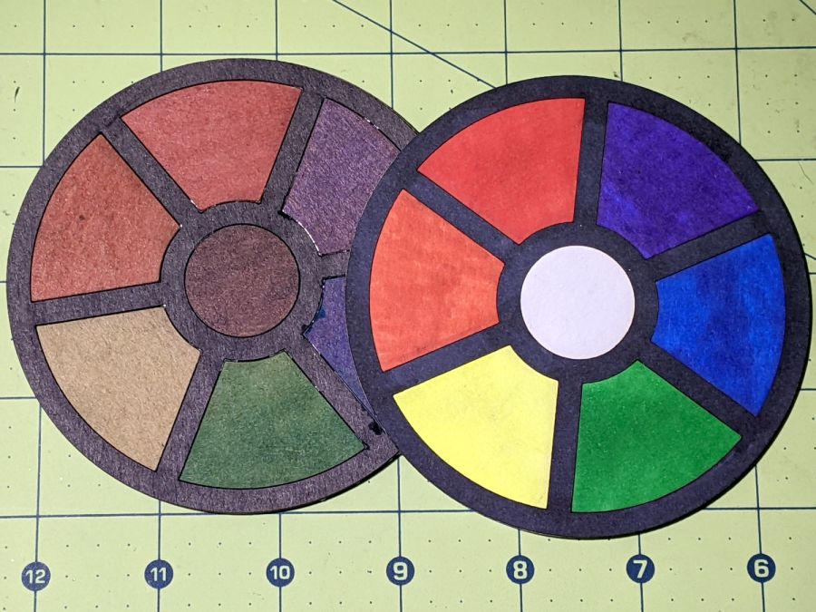
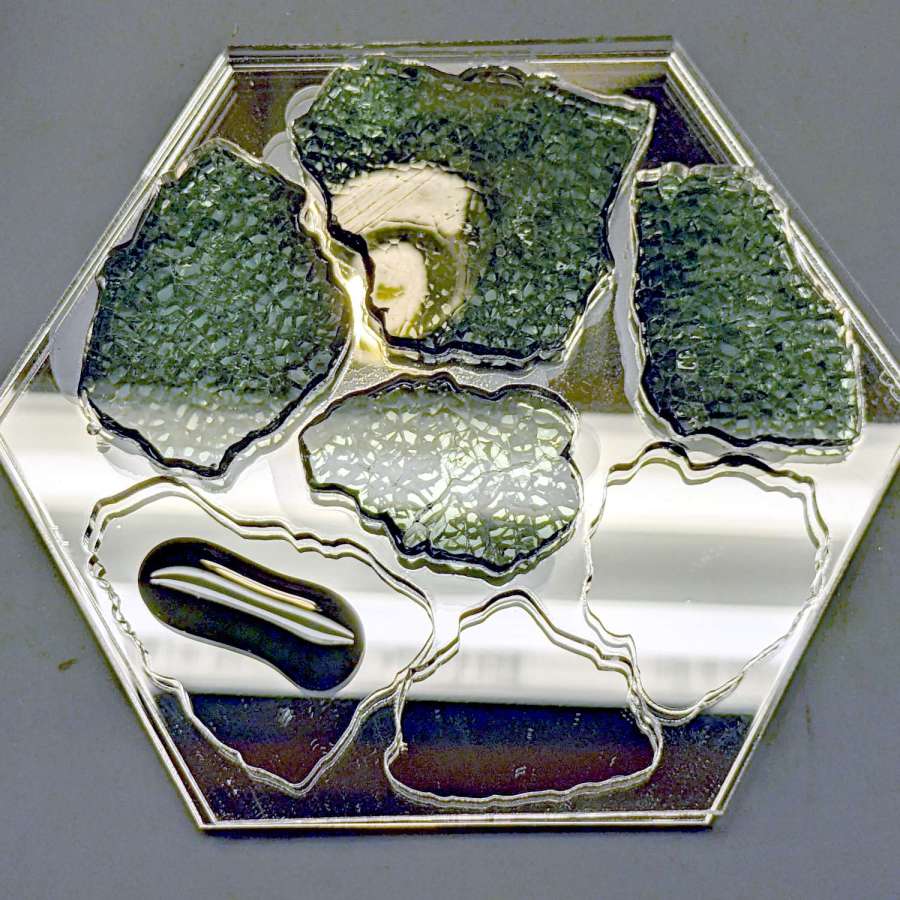
The middle one comes from a version of the original GCMC marquetry shape generator, tweaked to produce just the frame SVG, called by a Bash script to change the sash width, and imported into LightBurn for laser control:

I generated the plain disk for the bottom by deleting all the inner shapes.
The left and right coasters use LightBurn’s Offset tool to reduce the size of the interior holes on successive layers:

Although the GCMC version turned out OK, you’ll note it lacks the central disk, as I was unwilling to tweak the code enough to make the disk diameter vary with the kerf width.
Applying the LB Offset tool requires selecting only the inner shapes (it has an option to ignore the inner shapes) and applying the appropriate offset. Because the tool remembers its previous settings, it’s straightforward to step the offset from 1.0 mm to 7.0 mm on successive patterns.
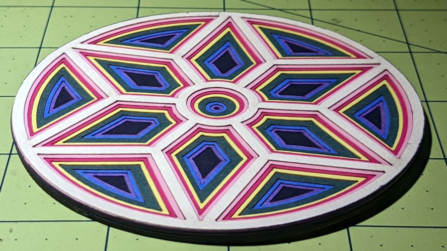
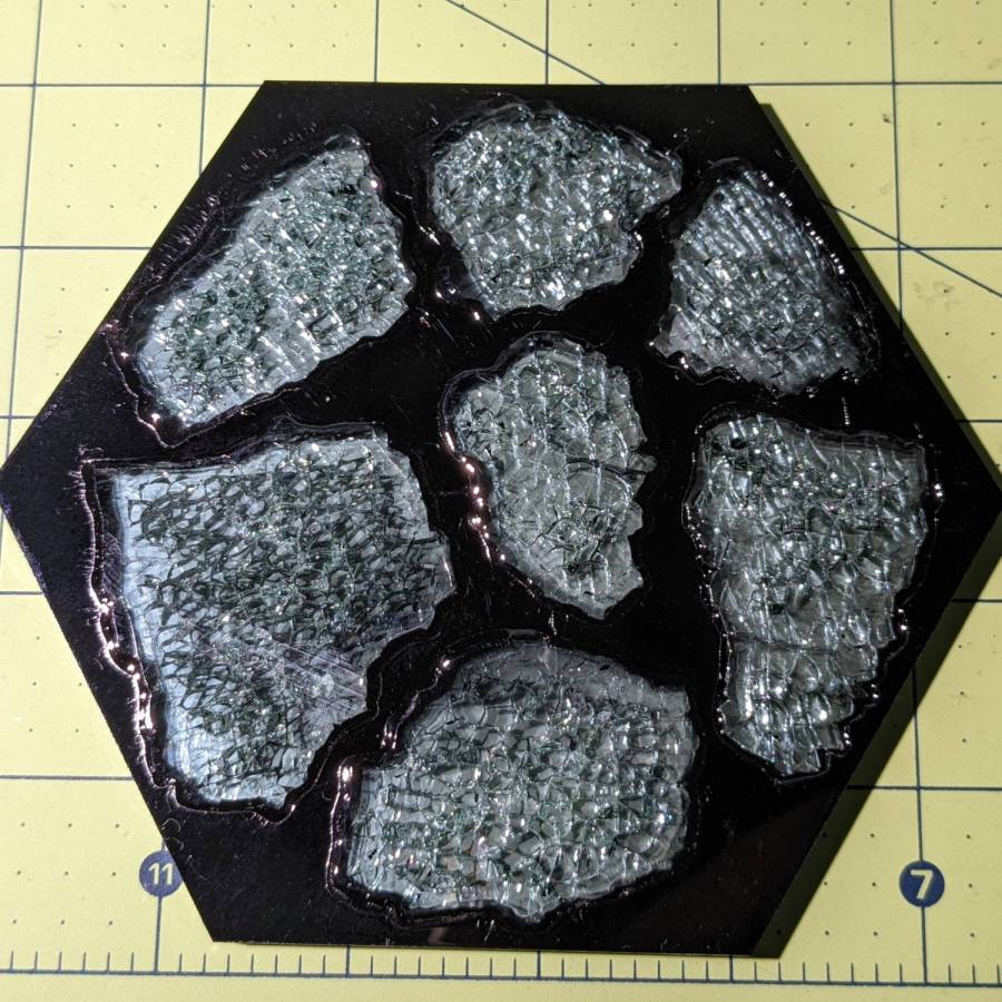
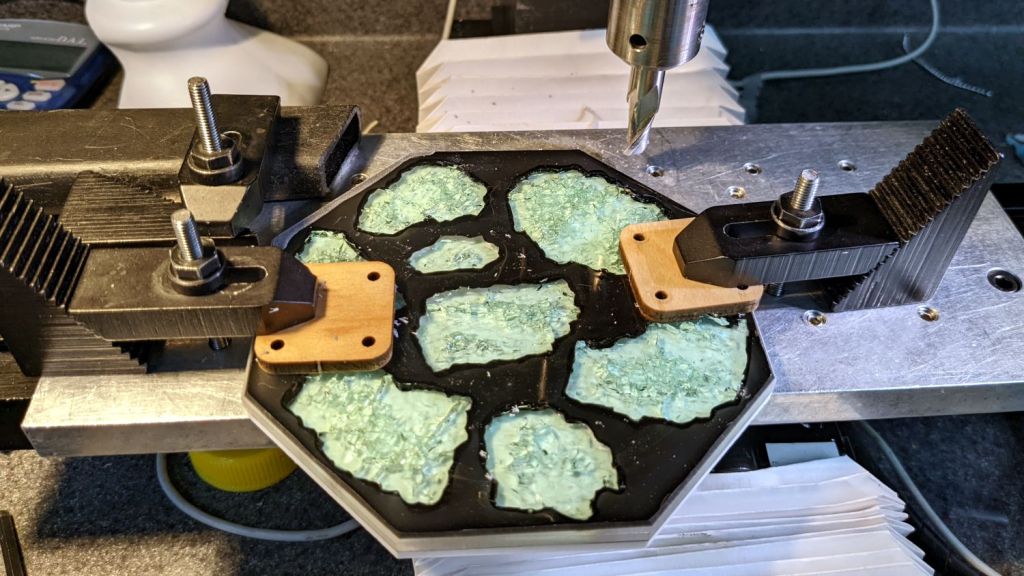
Applying glue (from a glue stick!) to the bottom of each disk, aligning them atop each other, and pressing them together becomes tedious in short order. If I had to do a lot of these, I’d be tempted to add three wings (not at 120° angles!) around the perimeter with holes for pegs, then stacking the layers in a fixture to ensure good alignment. A polygonal perimeter would simplify trimming the tabs.
Spray adhesive might be faster, but each layer would have sticky edges and the finished coaster would become a dust collector par excellence.
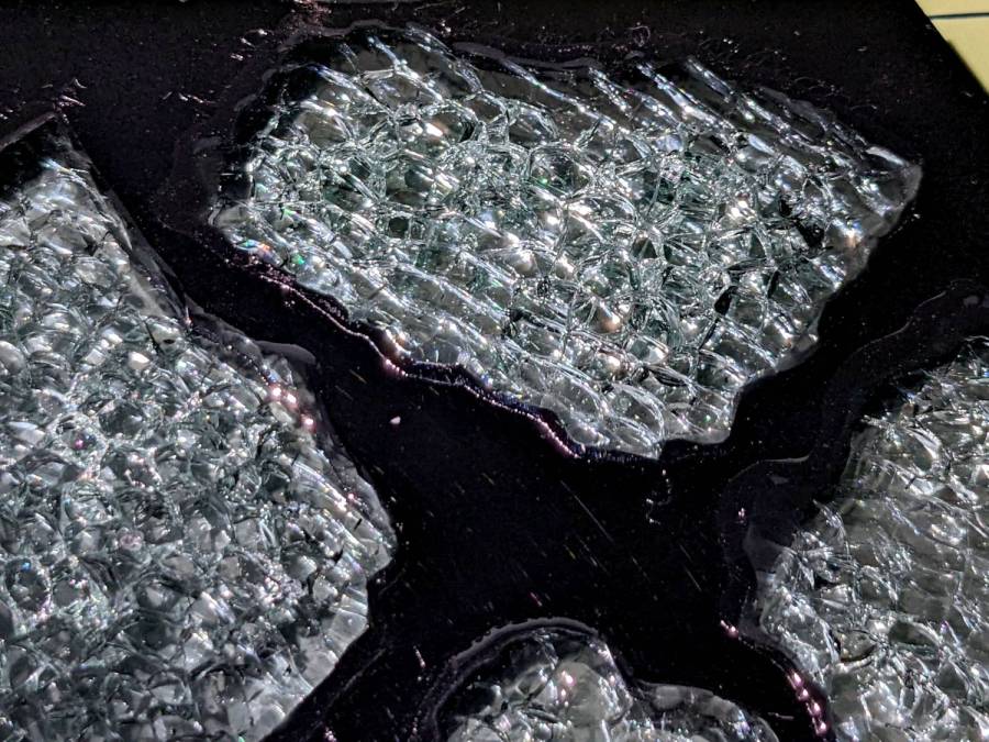
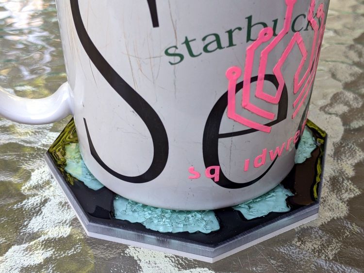
I like the overall effect, but …
The OpenSCAD source code as a GitHub Gist:
| #!/bin/bash | |
| # Layering paper cutouts | |
| # Ed Nisley KE4ZNU – 2022-08-21 | |
| Flags='-P 4 –pedantic' # quote to avoid leading hyphen gotcha | |
| SVGFlags='–svg –svg-no-movelayer –svg-opacity=1.0 –svg-toolwidth=0.2' | |
| # Set these to match your file layout | |
| ProjPath='/mnt/bulkdata/Project Files/Laser Cutter/Coasters/Source Code' | |
| LibPath='/opt/gcmc/library' | |
| ScriptPath=$ProjPath | |
| Script='Marquetry Layers.gcmc' | |
| [ -z "$1" ] && leaves="6" || leaves="$1" | |
| [ -z "$2" ] && aspect="0.50" || aspect="$2" | |
| [ -z "$3" ] && center="0.0mm" || center="$3" | |
| numlayers=8 | |
| sashmin=2.0 | |
| sashstep=2.0 | |
| sashmax=$(echo "$sashmin+$sashstep*($numlayers-1)" | bc) | |
| echo min: $sashmin step: $sashstep max: $sashmax | |
| for sash in $(seq $sashmin $sashstep $sashmax) ; do | |
| fn=Marq-$leaves-$aspect-$center-S$sash.svg | |
| echo Output: $fn | |
| gcmc $Flags $SVGFlags –include "$LibPath" \ | |
| -D "NumLeaves=$leaves" -D "LeafAspect=$aspect" -D "CenterDia=$center" \ | |
| -D "Sash=${sash}mm" \ | |
| "$ScriptPath"/"$Script" > "$fn" | |
| done |
| // Marquetry Layers | |
| // Ed Nisley KE4ZNU | |
| // 2022-08-21 layered paper test piece | |
| layerstack("Frame","Leaves","Rim","Base","Center","Tool1"); // SVG layers map to LightBurn colors | |
| //—– | |
| // Library routines | |
| include("tracepath.inc.gcmc"); | |
| include("varcs.inc.gcmc"); | |
| FALSE = 0; | |
| TRUE = !FALSE; | |
| //—– | |
| // Command line parameters | |
| // -D various useful tidbits | |
| // add unit to speeds and depths: 2000mm / -3.00mm / etc | |
| if (!isdefined("OuterDia")) { | |
| OuterDia = 120.0mm; | |
| } | |
| if (!isdefined("CenterDia")) { | |
| CenterDia = 20.0mm; | |
| } | |
| if (!isdefined("NumLeaves")) { | |
| NumLeaves = 8; | |
| } | |
| if (!isdefined("Sash")) { | |
| Sash = 4.0mm; | |
| } | |
| if (!isdefined("LeafAspect")) { | |
| LeafAspect = 0.50; | |
| } | |
| // Leaf values | |
| LeafStemAngle = 360.0deg/NumLeaves; // subtended by inner sides | |
| LeafStemHA = LeafStemAngle/2; | |
| LeafOAL = OuterDia/2 – Sash – (Sash/2)/sin(LeafStemHA); | |
| LeafWidth = LeafAspect*LeafOAL; | |
| L1 = (LeafWidth/2)/tan(LeafStemHA); | |
| L2 = LeafOAL – L1; | |
| // message("Len: ",LeafOAL," L1: ",L1," L2: ",L2); | |
| LeafTipHA = to_deg(atan(LeafWidth/2,L2)); // subtended by outer sides | |
| LeafTipAngle = 2*LeafTipHA; | |
| // message("Width: ",LeafWidth); | |
| // message("Tip HA: ",LeafTipHA); | |
| LeafID = CenterDia + 2*Sash; | |
| LeafOD = LeafID + LeafOAL; | |
| // message("ID: ",LeafID," OD: ",LeafOD); | |
| // Find leaf and rim vertices | |
| P0 = [(Sash/2) / sin(LeafStemHA),0.0mm]; | |
| m = tan(LeafStemHA); | |
| y0 = -(Sash/2) / cos(LeafStemHA); | |
| if (CenterDia) { // one sash width around center spot | |
| a = 1 + pow(m,2); | |
| b = 2 * m * y0; | |
| c = pow(y0,2) – pow(LeafID/2,2); | |
| xp = (-b + sqrt(pow(b,2) – 4*a*c))/(2*a); | |
| xn = (-b – sqrt(pow(b,2) – 4*a*c))/(2*a); | |
| y = xp*tan(LeafStemHA) – (Sash/2) / cos(LeafStemHA); | |
| P1 = [xp,y]; | |
| if (FALSE) { | |
| message("a: ",a); | |
| message("b: ",b); | |
| message("c: ",c); | |
| message("p: ",xp," n: ",xn," y: ",y); | |
| } | |
| } | |
| else { // force sharp point without center spot | |
| P1 = P0; | |
| } | |
| P2 = P0 + [L1,LeafWidth/2]; | |
| P3 = P0 + [LeafOAL,0mm]; | |
| P4 = P3 + [Sash/sin(LeafTipHA),0.0mm]; | |
| P5r = P4.x * sin(LeafTipHA) / sin(180deg – LeafStemHA – LeafTipHA); | |
| P5 = rotate_xy([P5r,0.0mm],LeafStemHA); | |
| P6 = rotate_xy(P4,LeafStemAngle); | |
| t2 = pow(tan(-LeafTipHA),2); | |
| a = 1 + t2; | |
| b = -2 * t2 * P4.x; | |
| c = t2 * pow(P4.x,2) – pow(P3.x,2); | |
| xp = (-b + sqrt(pow(b,2) – 4*a*c))/(2*a); | |
| xn = (-b – sqrt(pow(b,2) – 4*a*c))/(2*a); | |
| y = (xp – P4.x)*tan(-LeafTipHA); | |
| // message("p: ",xp," n: ",xn," y: ",y); | |
| P4a = [xp,y]; | |
| P6a = rotate_xy(P4a,LeafStemAngle – 2*atan(P4a.y,P4a.x)); | |
| if (FALSE) { | |
| message("P0: ",P0); | |
| message("P1: ",P1); | |
| message("P2: ",P2); | |
| message("P3: ",P3); | |
| message("P4: ",P4); | |
| message("P4a: ",P4a); | |
| message("P5: ",P5); | |
| message("P6: ",P6); | |
| message("P6a: ",P6a); | |
| } | |
| // Construct paths | |
| LeafPoints = {P1,P2,P3,[P2.x,-P2.y],[P1.x,-P1.y]}; | |
| if (P0 != P1) { | |
| StemArc = varc_ccw(P1 – [P1.x,-P1.y],LeafID/2); | |
| StemArc += [P1.x,-P1.y]; | |
| LeafPoints += StemArc; | |
| } | |
| RimChord = length(P4a – P6a); | |
| RimThick = OuterDia/2 – Sash – length(P5); | |
| RimPoints = {P4a,P5,P6a}; | |
| RimArc = varc_cw(P4a – P6a,P4a.x); | |
| RimArc += P6a; | |
| RimPoints += RimArc; | |
| //— Lay out the frame | |
| linecolor(0xff0000); | |
| layer("Frame"); | |
| if (CenterDia) { | |
| goto([CenterDia/2,0mm]); | |
| circle_cw([0mm,0mm]); | |
| } | |
| repeat(NumLeaves;i) { | |
| a = (i-1)*LeafStemAngle; | |
| tracepath(rotate_xy(LeafPoints,a)); | |
| } | |
| repeat(NumLeaves;i) { | |
| a = (i-1)*LeafStemAngle; | |
| tracepath(rotate_xy(RimPoints,a)); | |
| } | |
| linecolor(0xff0000); | |
| goto([OuterDia/2,0]); | |
| circle_cw([0mm,0mm]); | |