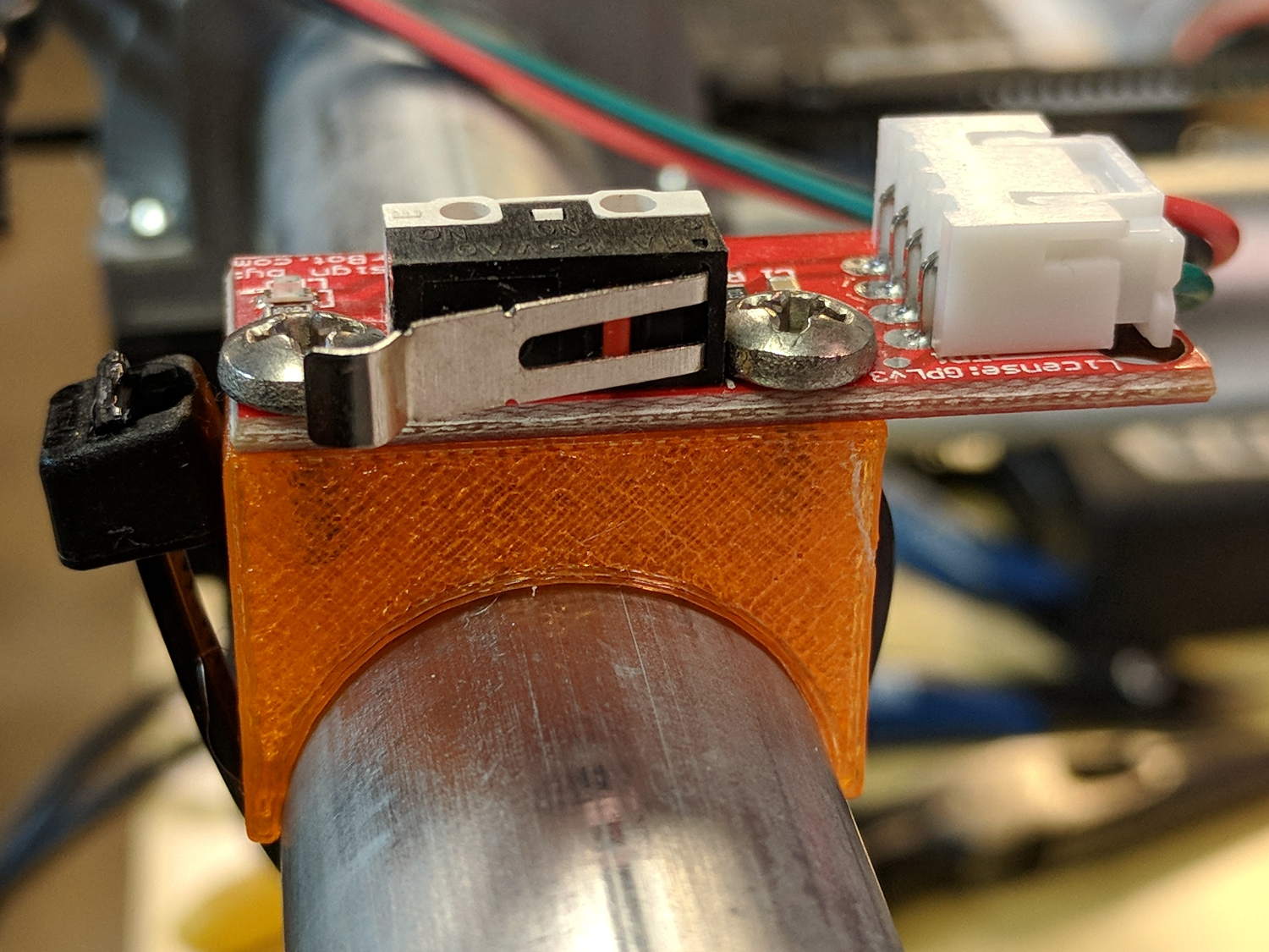
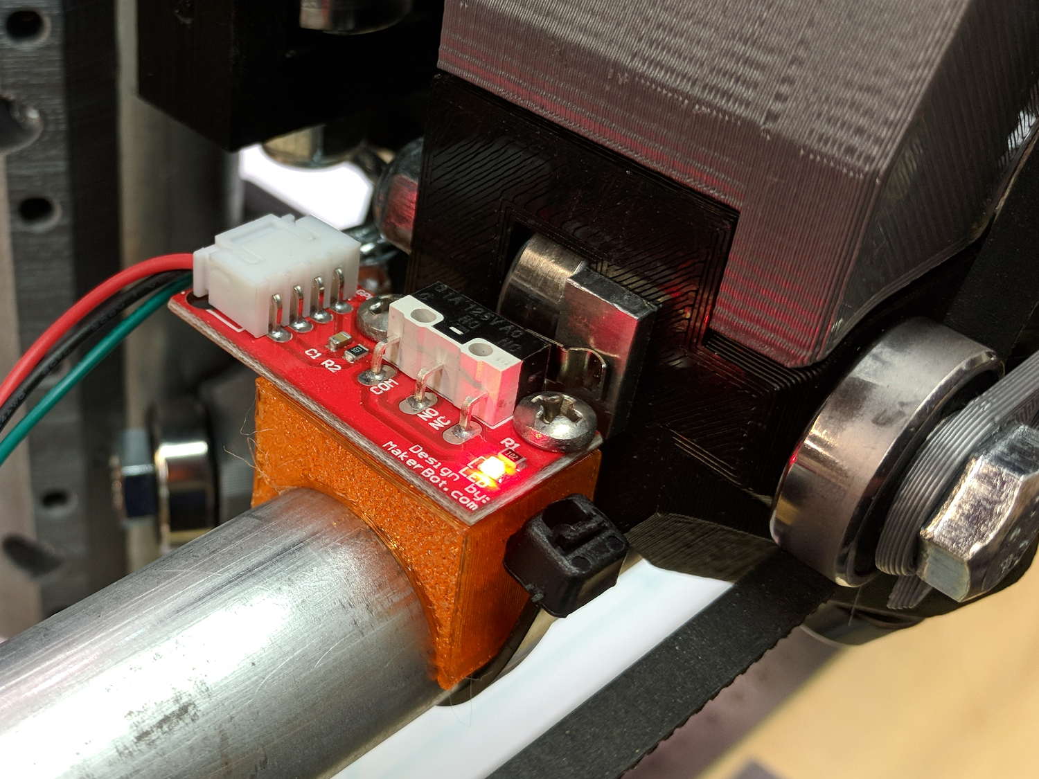
The folks I’ve been coaching through their plotter build project showed it off at the local MiniMakerFaire this past weekend. Next time around, I’ll insist they secure their circuit boards and use good wiring techniques, so as to avoid destroying more stepper drivers.
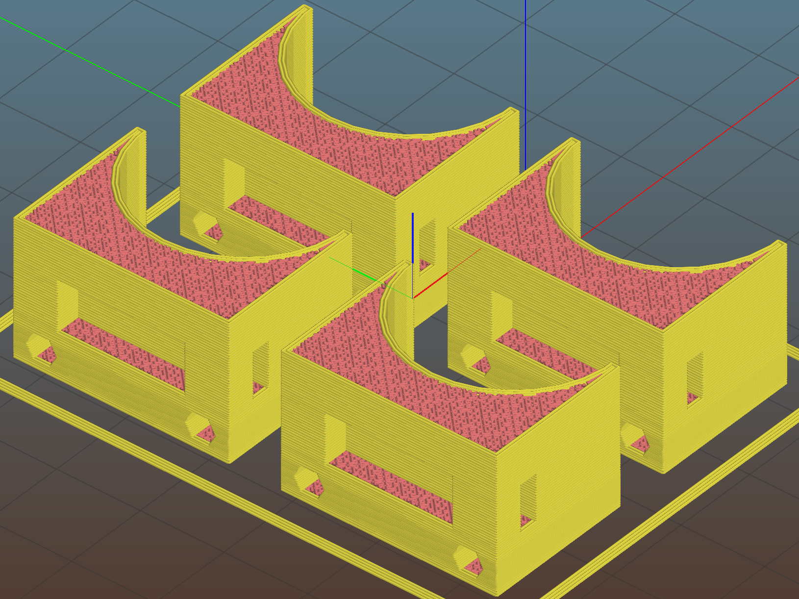
To that end, adding mounting holes to my proto board holder seems in order:
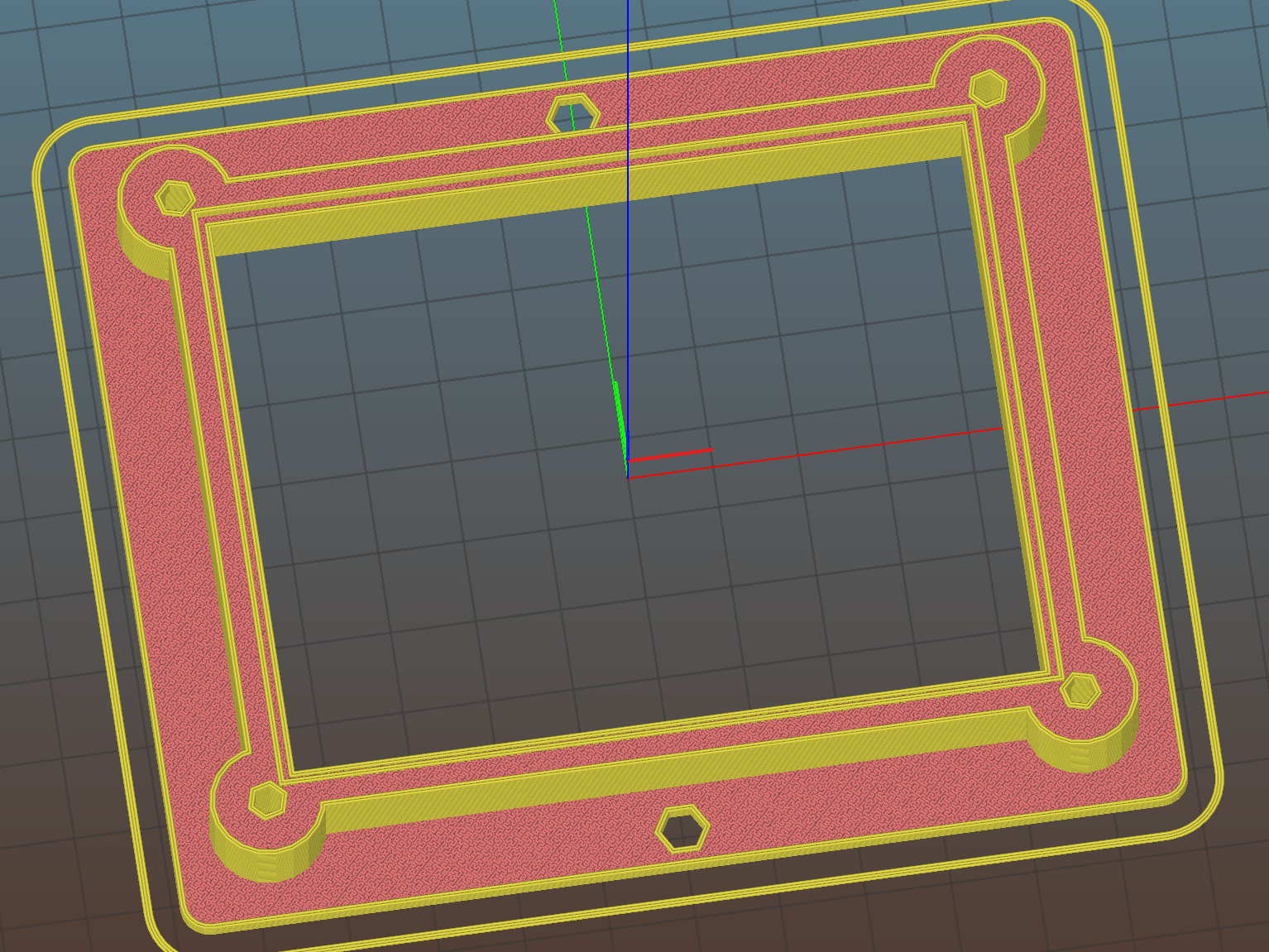
The board dimensions now live in an associative array, so you just pick the board name from a Configurator drop-down list:
/* [Options] */

PCBSelect = "ArdUno"; // ["20x80","40x60","30x70","50x70","70x90","80x120","ArdDuemil","ArdMega","ArdPro","ArdUno","ProtoneerCNC"]

PCB_NAME = 0;
PCB_DIMENSION = 1;

PCBSizes = [
  ["40x60",[40,60,1.6]],
  ["30x70",[30,70,1.6]],
  ["50x70",[50,70,1.6]],
  ["20x80",[20,80,1.6]],
  ["70x90",[70,90,1.6]],
  ["80x120",[80,120,1.6]],
  ["ArdDuemil",[69,84,1.6]],
  ["ArdMega",[102,53.5,1.6]],
  ["ArdPro",[53,53.5,1.6]],
  ["ArdUno",[69,53.1,1.6]],
  ["ProtoneerCNC",[69,53.1,1.6]],
];
Which seems easier than keeping track of the dimensions in comments.
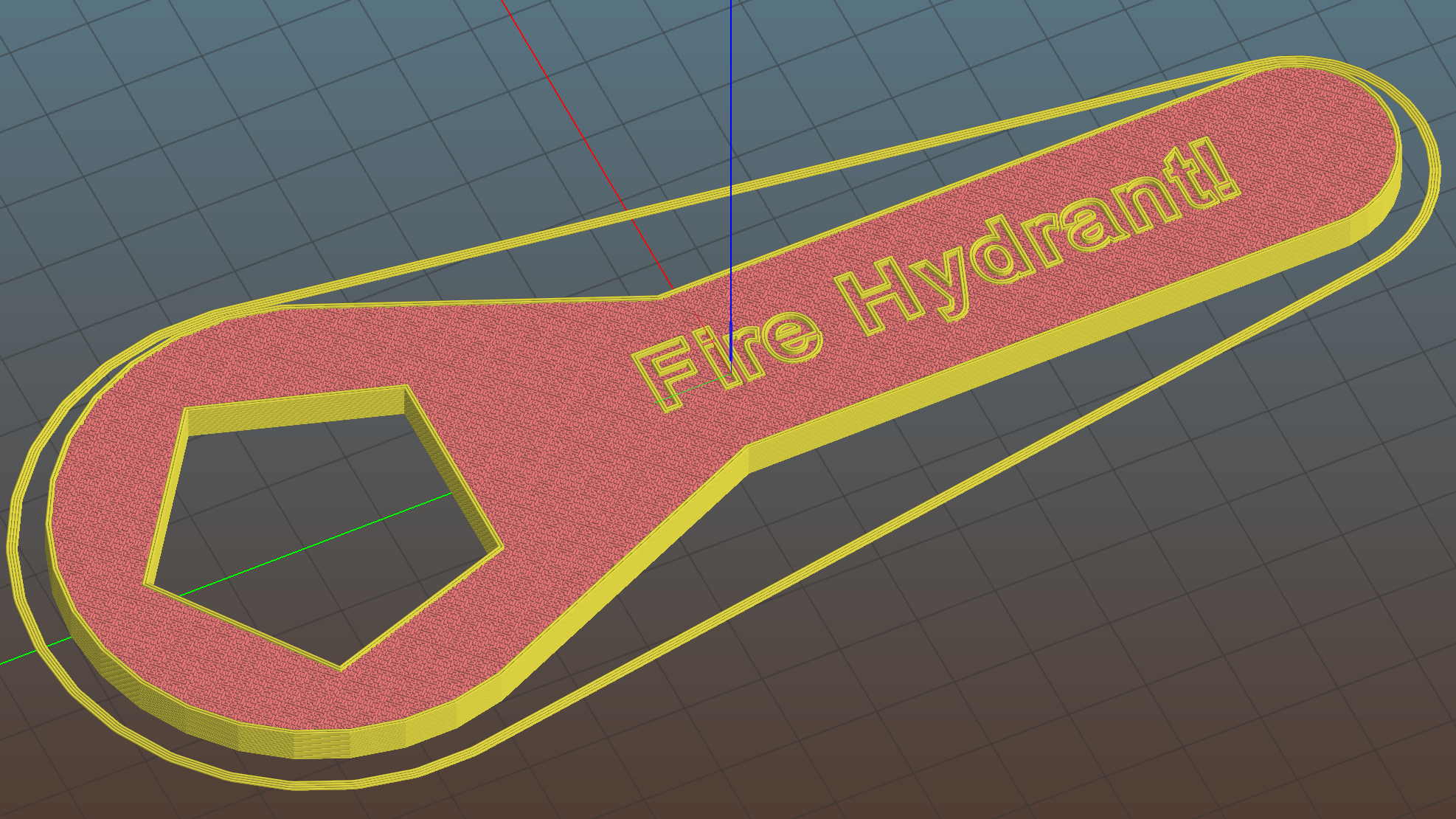
You can now put the PCB clamp screws and mounting holes on specific corners & sides, allowing oddball locations for Arduino boards with corner cutouts along the right edge:
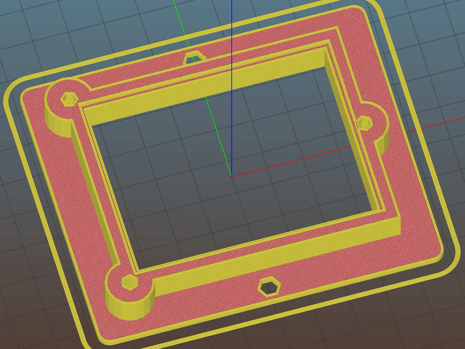
A “selector” notation separates the hole location from the board dimensions & coordinates:
ScrewSites = [
//  [-1,1],[1,1],[1,-1],[-1,-1],        // corners
//  [-1,0],[1,0],[0,1],[0,-1]           // middles
  [-1,1],[-1,-1],[1,0]                  // Arduinos
];
Might not be most obvious way, but it works for me. Most of the time, corner clamps seem just fine, so I’m not sure adding the clamp and mounting hole locations to the dimension array makes sense.
The OpenSCAD source code as a GitHub Gist:
| // Test support frame for proto boards | |
| // Ed Nisley KE4ZNU – Jan 2017 | |
| // June 2017 – Add side-mount bracket, inserts into bottom | |
| // 2017-11 – Selectable board sizes, chassis mounting holes | |
| /* [Options] */ | |
| PCBSelect = "ArdUno"; // ["20×80","40×60","30×70","50×70","70×90","80×120","ArdDuemil","ArdMega","ArdPro","ArdUno","ProtoneerCNC"] | |
| Layout = "Frame"; // [Frame, Bracket] | |
| ClampFlange = true; // external flange | |
| Mounts = true; // frame to chassis screw holes | |
| Channel = false; // wiring channel cutout | |
| WasherRecess = false; // cutout around screw head | |
| /* [Extrusion parameters] */ | |
| ThreadThick = 0.25; // [0.15, 0.20, 0.25] | |
| ThreadWidth = 0.40; | |
| function IntegerMultiple(Size,Unit) = Unit * ceil(Size / Unit); | |
| /* [Hidden] */ | |
| Protrusion = 0.1; | |
| HoleWindage = 0.2; | |
| inch = 25.4; | |
| Tap4_40 = 0.089 * inch; | |
| Clear4_40 = 0.110 * inch; | |
| Head4_40 = 0.211 * inch; | |
| Head4_40Thick = 0.065 * inch; | |
| Nut4_40Dia = 0.228 * inch; | |
| Nut4_40Thick = 0.086 * inch; | |
| Washer4_40OD = 0.270 * inch; | |
| Washer4_40ID = 0.123 * inch; | |
| Tap6_32 = 0.106 * inch; | |
| Clear6_32 = 0.166 * inch; | |
| Head6_32 = 0.251 * inch; | |
| Head6_32Thick = 0.097 * inch; | |
| Nut6_32Dia = 0.312 * inch; | |
| Nut6_32Thick = 0.109 * inch; | |
| Washer6_32OD = 0.361 * inch; | |
| Washer6_32ID = 0.156 * inch; | |
| ID = 0; | |
| OD = 1; | |
| LENGTH = 2; | |
| //- PCB sizes | |
| // the list must contain all the selection names as above | |
| //* [Hidden] */ | |
| PCB_NAME = 0; | |
| PCB_DIMENSION = 1; | |
| PCBSizes = [ | |
| ["40×60",[40,60,1.6]], | |
| ["30×70",[30,70,1.6]], | |
| ["50×70",[50,70,1.6]], | |
| ["20×80",[20,80,1.6]], | |
| ["70×90",[70,90,1.6]], | |
| ["80×120",[80,120,1.6]], | |
| ["ArdDuemil",[69,84,1.6]], | |
| ["ArdMega",[102,53.5,1.6]], | |
| ["ArdPro",[53,53.5,1.6]], | |
| ["ArdUno",[69,53.1,1.6]], | |
| ["ProtoneerCNC",[69,53.1,1.6]], | |
| ]; | |
| PCBIndex = search([PCBSelect],PCBSizes)[0]; | |
| PCBSize = PCBSizes[PCBIndex][PCB_DIMENSION]; | |
| //echo(str("PCB Size Table: ",PCBSizes)); | |
| //echo(str("PCB Select: ",PCBSelect)); | |
| //echo(str("PCB Index: ",PCBIndex)); | |
| echo(str("PCB Size: ",PCBSize)); | |
| /* [Sizes] */ | |
| WallThick = 4.0; // basic frame structure | |
| FrameHeight = 10.0; | |
| /* [Hidden] */ | |
| Insert = [3.9,4.6,5.8]; | |
| PCBShelf = 1.0; // width of support rim under PCB | |
| Clearance = 1*[ThreadWidth,ThreadWidth,0]; // around PCB on all sides | |
| ScrewOffset = ThreadWidth + Insert[OD]/2; // beyond PCB edges | |
| echo(str("Screw offset: ",ScrewOffset)); | |
| /* [Screw Selectors] */ | |
| // ij selectors for PCB clamp screw holes: -1/0/1 = left/center/right , bottom/center/top | |
| ScrewSites = [ | |
| // [-1,1],[1,1],[1,-1],[-1,-1], // corners | |
| // [-1,0],[1,0],[0,1],[0,-1] // middles | |
| [-1,1],[-1,-1],[1,0] // Arduinos | |
| ]; | |
| // ij selectors for frame mounting holes | |
| MountSites = [ | |
| [0,-1],[0,1], | |
| // [-1,0],[1,0] | |
| ]; | |
| function ScrewAngle(ij) = (ij[0]*ij[1]) ? ij[0]*ij[1]*15 : ((!ij[1]) ? 30 : 0); // align screw sides | |
| OAHeight = FrameHeight + Clearance[2] + PCBSize[2]; // total frame height | |
| echo(str("OAH: ",OAHeight)); | |
| BossOD = 2*Washer4_40OD; // make bosses oversized for washers | |
| FlangeExtension = 4.0 + Washer6_32OD/2 – WallThick; // beyond frame structure | |
| FlangeThick = IntegerMultiple(2.0,ThreadThick); // plate under frame | |
| Flange = PCBSize | |
| + 2*[ScrewOffset,ScrewOffset,0] | |
| + [BossOD,BossOD,0] | |
| + [2*FlangeExtension,2*FlangeExtension,(FlangeThick – PCBSize[2])] | |
| ; | |
| FlangeRadius = BossOD/4; | |
| echo(str("Flange: ",Flange)); | |
| NumSides = 4*5; | |
| WireChannel = [Flange[0],15.0,3.0 + PCBSize[2]]; // ad-hoc wiring cutout | |
| WireChannelOffset = [ | |
| Flange[0]/2,0,(FrameHeight + PCBSize[2] – WireChannel[2]/2) | |
| ]; | |
| //- Adjust hole diameter to make the size come out right | |
| module PolyCyl(Dia,Height,ForceSides=0) { // based on nophead's polyholes | |
| Sides = (ForceSides != 0) ? ForceSides : (ceil(Dia) + 2); | |
| FiiDia = Dia / cos(180/Sides); | |
| cylinder(r=(FiiDia + HoleWindage)/2,h=Height,$fn=Sides); | |
| } | |
| //- Build things | |
| if (Layout == "Frame") | |
| difference() { | |
| union() { // body block | |
| translate([0,0,OAHeight/2]) | |
| cube(PCBSize + Clearance + [2*WallThick,2*WallThick,FrameHeight],center=true); | |
| for (ij = ScrewSites) // screw bosses | |
| if (ij[0] != 0 || ij[1] != 0) | |
| translate([ij[0]*(PCBSize[0]/2 + ScrewOffset), | |
| ij[1]*(PCBSize[1]/2 + ScrewOffset), | |
| 0]) | |
| cylinder(d=BossOD,h=OAHeight,$fn=NumSides); | |
| if (ClampFlange) // flange for work holder & mounting screw holes | |
| linear_extrude(height=Flange[2]) | |
| hull() | |
| for (i=[-1,1], j=[-1,1]) { | |
| translate([i*(Flange[0]/2 – FlangeRadius),j*(Flange[1]/2 – FlangeRadius)]) | |
| circle(r=FlangeRadius,$fn=NumSides); // convenient rounding size | |
| } | |
| } | |
| for (ij = ScrewSites) { // screw position indeies | |
| if (ij[0] != 0 || ij[1] != 0) { | |
| translate([ij[0]*(PCBSize[0]/2 + ScrewOffset), | |
| ij[1]*(PCBSize[1]/2 + ScrewOffset), | |
| -Protrusion]) | |
| rotate(ScrewAngle(ij)) | |
| PolyCyl(Clear4_40,(OAHeight + 2*Protrusion),6); // screw clearance holes | |
| translate([ij[0]*(PCBSize[0]/2 + ScrewOffset), | |
| ij[1]*(PCBSize[1]/2 + ScrewOffset), | |
| -Protrusion]) | |
| rotate(ScrewAngle(ij)) | |
| PolyCyl(Insert[OD],OAHeight – PCBSize[2] – 3*ThreadThick + Protrusion,6); // inserts | |
| if (WasherRecess) | |
| translate([ij[0]*(PCBSize[0]/2 + ScrewOffset), | |
| ij[1]*(PCBSize[1]/2 + ScrewOffset), | |
| OAHeight – PCBSize[2]]) | |
| PolyCyl(1.2*Washer4_40OD,(PCBSize[2] + Protrusion),NumSides); // optional washer recess | |
| } | |
| } | |
| if (Mounts) | |
| for (ij = MountSites) | |
| translate([ij[0]*(Flange[0]/2 – Washer6_32OD/2),ij[1]*(Flange[1]/2 – Washer6_32OD/2),-Protrusion]) | |
| rotate(ScrewAngle(ij)) | |
| PolyCyl(Clear6_32,(Flange[2] + 2*Protrusion),6); | |
| translate([0,0,OAHeight/2]) // through hole below PCB | |
| cube(PCBSize – 2*[PCBShelf,PCBShelf,0] + [0,0,2*OAHeight],center=true); | |
| translate([0,0,(OAHeight – (PCBSize[2] + Clearance[2])/2 + Protrusion/2)]) // PCB pocket on top | |
| cube(PCBSize + Clearance + [0,0,Protrusion],center=true); | |
| if (Channel) | |
| translate(WireChannelOffset) // opening for wires from bottom side | |
| cube(WireChannel + [0,0,Protrusion],center=true); | |
| } | |
| // Add-on bracket to hold smaller PCB upright at edge | |
| PCB2Insert = [3.0,4.9,4.1]; | |
| PCB2OC = 45.0; | |
| if (Layout == "Bracket") | |
| difference() { | |
| hull() // frame body block | |
| for (i=[-1,1]) // bosses around screws | |
| translate([i*(PCBSize[0]/2 + ScrewOffset),0,0]) | |
| cylinder(r=Washer4_40OD,h=OAHeight,$fn=NumSides); | |
| for (i=[-1,1]) // frame screw holes | |
| translate([i*(PCBSize[0]/2 + ScrewOffset),0,-Protrusion]) | |
| rotate(i*180/(2*6)) | |
| PolyCyl(Clear4_40,(OAHeight + 2*Protrusion),6); | |
| for (i=[-1,1]) // PCB insert holes | |
| translate([i*PCB2OC/2,(Washer4_40OD + Protrusion),OAHeight/2]) | |
| rotate([90,0,0]) | |
| cylinder(d=PCB2Insert[OD],h=2*(Washer4_40OD + Protrusion),$fn=6); | |
| } | |