Ed Nisley's Blog: Shop notes, electronics, firmware, machinery, 3D printing, laser cuttery, and curiosities. Contents: 100% human thinking, 0% AI slop.
Category: Software
General-purpose computers doing something specific
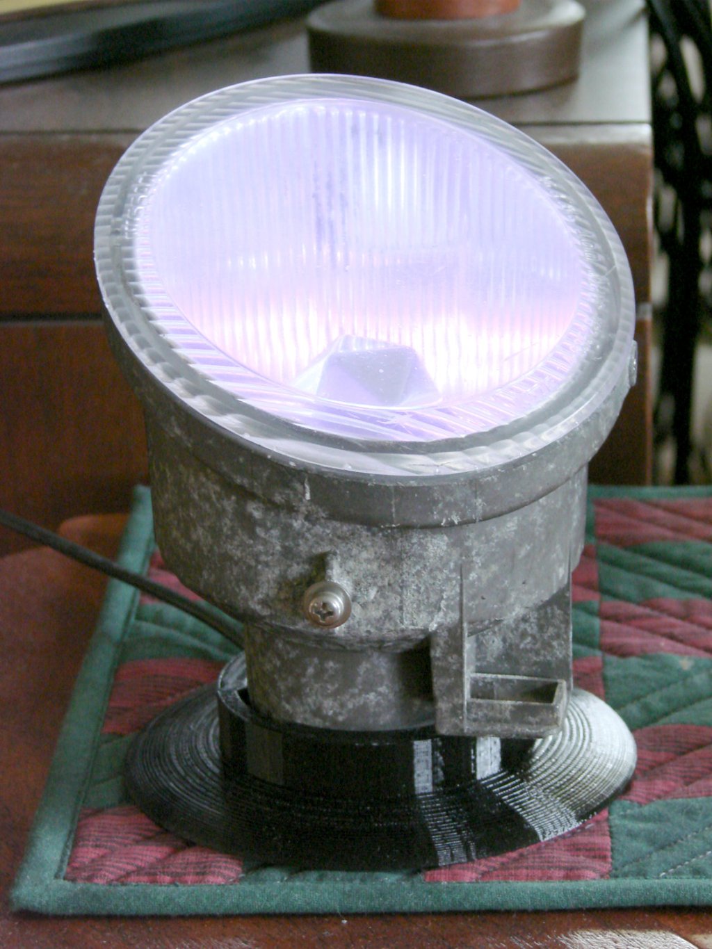
The Nissan fog lamp looks pretty good pointing at the ceiling:
Nissan Fog Lamp – table mount
I briefly considered sandblasting the shell to knock back the corrosion, but came to my senses: this is art!
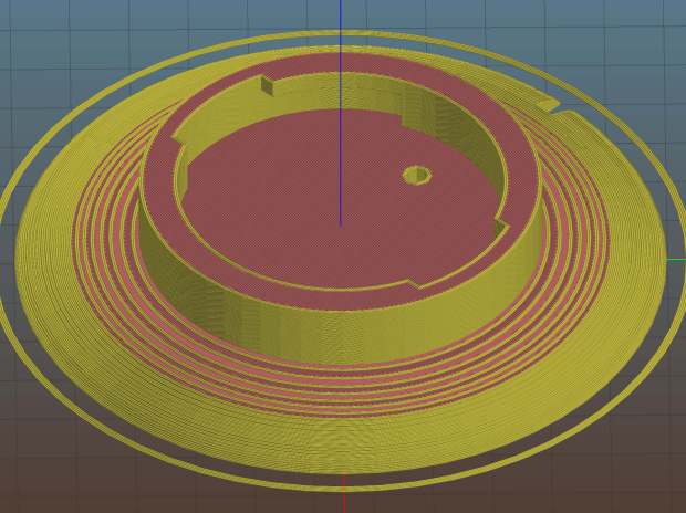
The shell has a bayonet mount intended for the cable connector, but a bout of solid modeling produced a matching twist-lock desk stand:
Nissan Fog Light Base – Slic3r preview
The locking dogs overhang little enough, relative to their diameter, to let the thing build without internal supports. Took about three hours without any intervention at all.
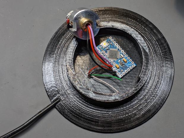
The little hole matches up with the slot on the bottom holding a USB cable bringing power from a wall charger:
Nissan Fog Lamp – table mount interior
It’s a knockoff Arduino Pro Mini without the USB interface found on a Nano, so the USB data wires don’t connect to anything.
The base might look better under a layer of (black?) epoxy, although I’m definitely a fan of those brutalist 3D printed striations.
This file contains hidden or bidirectional Unicode text that may be interpreted or compiled differently than what appears below. To review, open the file in an editor that reveals hidden Unicode characters.
Learn more about bidirectional Unicode characters
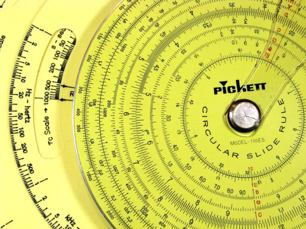
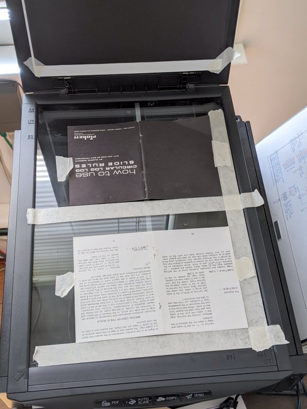
I gimmicked a scanner fixture to align a pair of pages:
Pickett 110-ES Scanning Fixture
Yes, I destroyed the collectible value of my manual by removing two slightly rusted staples.
The black paper taped to the scanner lid prevents the type on the upper surface of the paper from producing dark blurs.
Set up XSane for batch scanning (one selection over each two-page spread), get a pipeline going (disassembly → face up → face down → reassembly), and eventually create 34 images named Scan-??.jpg. They’re in color, although it matters only for the rust stains around the staple holes, with the contrast stretched enough to make them mostly B&W.
Somehow, Pickett printed / cut half the sheets slightly off-kilter, so I rotated them -1° rotation to re-align the text. To simplify plucking the rotated pages out of the image, composite the spread atop a blank white background:
for i in $(seq -w 3 2 33) ; do composite -compose atop Scan-$i.jpg -size 2200x1400 -geometry +100+100 canvas:white -rotate -1 Comp-$i.jpg ; done
Rather than thinking too hard, do exactly the same thing to the other pages without rotation:
for i in $(seq -w 2 2 34) ; do composite -compose atop Scan-$i.jpg -size 2200x1400 -geometry +100+100 canvas:white -rotate 0 Comp-$i.jpg ; done
Each scanned image has two pages, so crop it into two files with names corresponding to the actual page numbers:
for i in $(seq 2 2 34) ; do convert -crop 960x1240+1050+110 Comp-$i.jpg Crop-$(( $i - 1 )).jpg ; done
for i in $(seq 3 2 34) ; do convert -crop 960x1240+130+110 Comp-$i.jpg Crop-$(( $i - 1 )).jpg ; done
for i in $(seq 3 2 33) ; do convert -crop 960x1240+1050+110 Comp-$i.jpg Crop-$(( 66 - $i )).jpg ; done
for i in $(seq 2 2 32) ; do convert -crop 960x1240+110+110 Comp-$i.jpg Crop-$(( 66 - $i )).jpg ; done
Fix the single-digit pages to simplify globbing later on:
rename 's/-/-0/' Crop-[1-9].jpg
A bit of tedious fixup for some truly misaligned sheets produced images with slightly different sizes, so composite all of them onto slightly larger backgrounds to avoid screwing up the PDF conversion:
mkdir Final
for f in Crop* ; do composite -compose atop $f -size 1000x1300 -geometry +10+10 canvas:white -Final/$f ; done
Then jam them into a PDF for convenience:
cd Final
convert Crop-C[12].jpg Crop-[0-6]*.jpg Crop-C[34].jpg "Pickett 110-ES Circular Slide Rule Manual.pdf"
You can print it six-up to a sheet to produce text just about the same size as the original manual. If you omit (blank) cover pages 2, 67, and 68, the whole thing fits neatly on 11 sheets of paper.
Someone with better facilities and more attention to detail can surely produce a better-looking result, but this will be better than nothing.
It’s a bitty thing, with the CRT about 0.7 inch long, scanned directly from my original Tek CC.
Import the PNG image into FreeCAD at 0.2 mm below the XY plane, resize it upward a smidge so the CRT is maybe 0.8 inch long, then trace “wires” all over it:
Tek Logo – FreeCAD tracing – overlay
Given FreeCAD’s default gradient background, the wires definitely don’t stand out by themselves:
Tek Logo – FreeCAD tracing – vectors
Several iterations later, the vectorized logo sits at the correct angle and distance from the origin at the center:
Tek Logo – FreeCAD tracing – rotated
The cheerful colors correspond to various “groups” and make it easier to find errant vectors.
Rather than figure out how to coerce FreeCAD into converting wires into proper G-Code, export the vectors into a DXF file and slam it into DXF2GCODE:
Tek Logo – DXF2GCODE vectors
Export as G-Code, iterate around the whole loop a few times to wring out the obvious mistakes, indulge in vigorous yak shaving, eventually decide it’s Good Enough™ for the moment.
Protip: set DFX2GCODE to put “0” digits before the decimal point to eliminate spaces between the coordinate axes and the numeric values which should not matter in the least, but which confuse NCViewer into ignoring the entire file.
Tinker the script running the GCMC source code to prepend the logo G-Code to the main file and it all comes out in one run:
Tek CC – with vectorized logo – cutting
That’s the top deck, laminated in plastic, affixed to a Cricut sticky mat on the MPCNC platform, ready for drag-knife cutting.
Assembled with a snappy red hairline:
Tek CC – Classic Tek Logo vectorized – red hairline
Isn’t it just the cutest thing you’ve seen in a while?
It needs more work, but it’s pretty close to right.
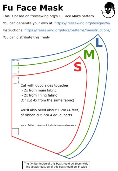
A local hospital contacted Mary’s quilting group to sew up cloth covers to prolong the life of their medical-grade N95 masks. Their recommended pattern, the Fu Face Mask from the FreeSewing group, comes in three sizes:
Freesewing – Fu Mask
N.B.: Use their original PDF, because a JPG picture probably won’t come out at the right size.
Also N.B.: Used by itself, this is not a medical-grade filter mask.
The patterns do not include the usual 1/4 inch seam allowance around the outside, so I cranked out 3D printed plastic cutting templates.
If you’re not interested in 3D printing, 2D print the PDF file on cardboard, sketch a seam allowance, and cut it out, as quilters have been doing since slightly after home printers happened.
The plan of attack:
Convert mask outlines into a bitmap image (GIMP)
Create Bezier curves by tracing outlines (Inkscape)
Save curves as SVG files
Convert SVG into solid model (OpenSCAD)
Add stiffening ribs &c
Save as STL solid model
Slice into G-Code file (Slic3r)
Fire the M2!
So, we begin …
Import the PDF into The GIMP, delete the text & suchlike, convert to monochrome, and save the pattern outlines as a PNG file:
Fu Facemask – outlines
It turns out Inkscape can directly import the PDF, but it valiantly tries to convert all the text and the incidental graphic elements, none of which will be useful in this situation. It’s easier to delete them in The GIMP and make a bank shot off a PNG file.
Import the PNG into Inkscape and trace one outline with the Bezier curve tool:
Fu Mask – Inkscape Bezier trace
If you squint really carefully, you’ll see Bezier control handles sticking out of the nodes. I laid three nodes along the top arc and four along the right side, but do what’cha like; the Insert key or Shift+I inserts and Delete removes nodes. It’s easier to center a node in the middle of the PNG line with snapping turned off: Shift+drag while mousing or globally with #.
You could unleash the bitmap auto-tracer, but it generates a bazillion uselessly tiny Bezier curves.
When you’re happy, select and copy the path with Ctrl+C, paste it into a shiny new Inkscape document (Ctrl+N) with Ctrl-V, save it with a catchy file name like Fu Mask - Small - nominal.svg, and close that document to return to the document with the PNG outlines and the original path.
Select the original path again, create a dynamic offset with Ctrl+J, open the XML editor with Ctrl+Shift+X (which automagically selects the proper SVG element), and change the inkscape:radius value from 0 to 6.35 (mm, which everyone should use) to get a 1/4 inch seam allowance:
Fu Mask – Inkscape XML Editor – Offset radius
The path will puff out with curved corners:
Fu Mask – Inkscape offset
Copy into a new document, save as Fu Mask - Small - seam allowance.svg, and close.
Repeat that process for each of the three mask sizes to create three pairs of SVG files: the nominal mask outline and the corresponding seam allowance outline for each size.
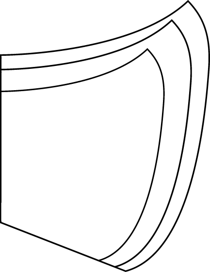
The OpenSCAD program imports the SVG files, removes the nominal outline from within the seam allowance to leave the outline, adds stiffening ribs, and stamps an ID letter on both sides of the central button:
Fu Mask Cutting Template – Small – solid model
Choose one of the three sizes with the OpenSCAD customizer, save the resulting model as an STL file, repeat for the three sizes, and you’re done.
This process can convert any outline paths in SVG files into cutting templates, so, should the Fu Mask not suit your fancy, Use The Source.
For convenience, the STL files are on Thingiverse.
This file contains hidden or bidirectional Unicode text that may be interpreted or compiled differently than what appears below. To review, open the file in an editor that reveals hidden Unicode characters.
Learn more about bidirectional Unicode characters
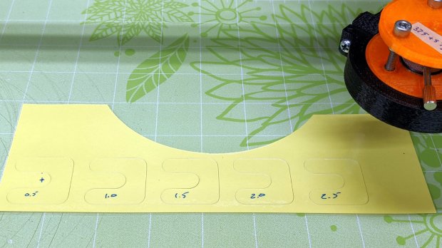
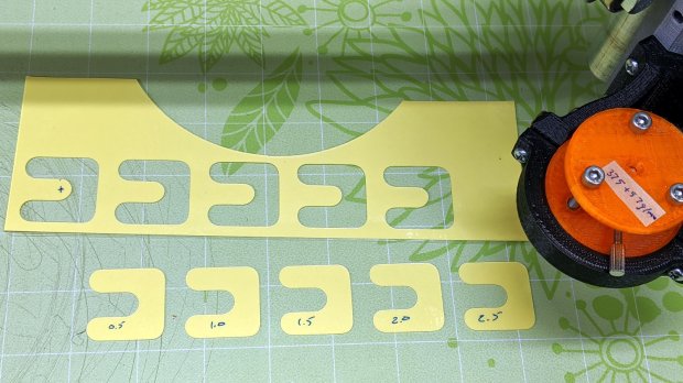
It’s not obvious, but each pattern steps downward by 0.5 mm from left to right. With the spring force equal to 375 g + 57 g/mm, the downforce ranges from 400 to 520 g over the five patterns.
Laminated scrap, meet drag knife:
Drag Knife Cal – Depth – as cut
Pulling up on the surrounding scrap left the patterns on the sticky mat:
Drag Knife Cal – Depth – extracted
Which suggested any cutting force would work just fine.
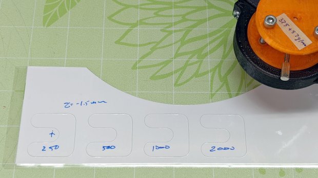
Flushed with success, I cut some speed variations at the minimum depth of Z=-0.5 mm = 400 g:
Drag Knife Cal – Speed – 0.5 mm – as cut
The blade cut through the top laminating film, the paper, and some sections of the bottom film, but mostly just scored the latter.
Repeating at Z=-1.5 mm = 460 g didn’t look much different:
Drag Knife Cal – Speed – 1.5 mm – as cut
However, the knife completely cut all the patterns:
Drag Knife Cal – Speed – 1.5 mm – extracted
As far as I can tell, the cutting speed doesn’t make much difference, although the test pattern is (deliberately) smooth & flowy like the Tek CC deck outlines. I’d been using 1000 mm/min and 2000 mm/min seems scary-fast, so 1500 mm/min may be a good compromise.
This file contains hidden or bidirectional Unicode text that may be interpreted or compiled differently than what appears below. To review, open the file in an editor that reveals hidden Unicode characters.
Learn more about bidirectional Unicode characters
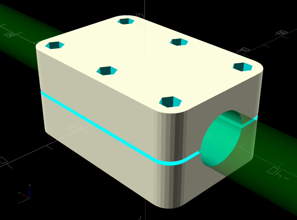
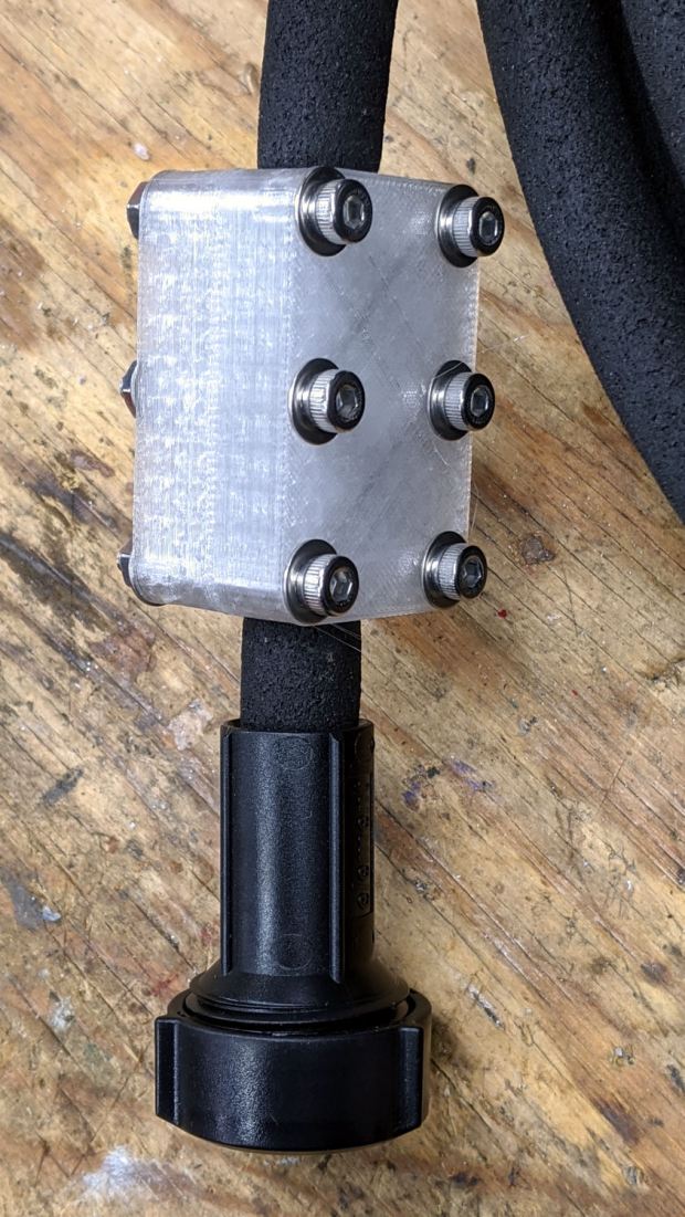
One of two new round rubber soaker hoses arrived with a slight crimp, enough to suggest it would crumble at an inopportune moment. Rather than return the hose for something that’s not an obvious failure, I clamped the crimp:
Round Soaker Hose Splice – top
Unlike the clamps for the punctured flat soaker hoses, this one doesn’t need to withstand much pressure and hold back a major leak, so I made the pieces a bit thicker and dispensed with the aluminum backing plates:
This file contains hidden or bidirectional Unicode text that may be interpreted or compiled differently than what appears below. To review, open the file in an editor that reveals hidden Unicode characters.
Learn more about bidirectional Unicode characters
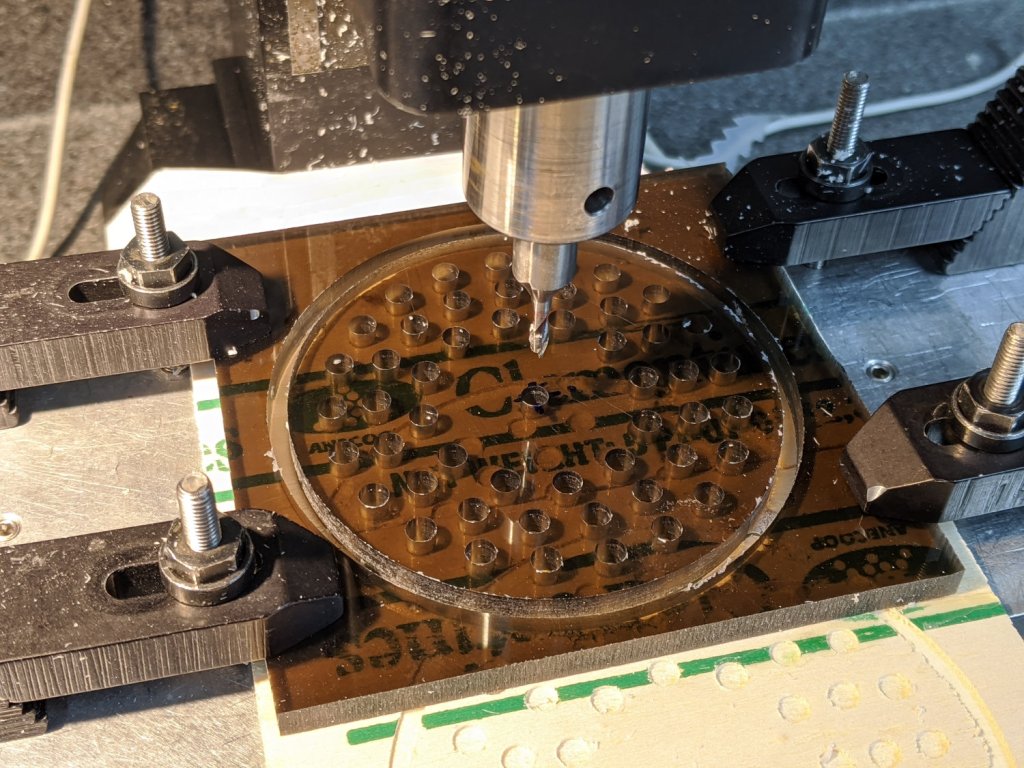
Our Young Engineer recently rented a house, now knows why our sinks have CNC-machined strainers, and asked for something better than the disgusting stainless mesh strainer in the kitchen sink.
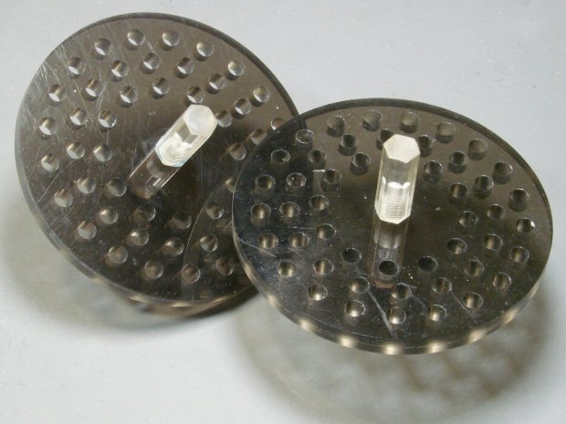
Being a doting father, I turned out a pair to get a pretty one:
CNC Sink Strainer – overview
They’re made from the same scrap smoked acrylic as the ones in our sinks:
CNC Sink Strainer
They’re definitely upscale from the (not watertight!) 3D printed version I built for a Digital Machinist column to explain OpenSCAD modeling:
Strainer plate fill
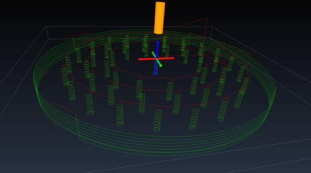
This time around, though, I rewrote the subtractive design in GCMC, with helical milling for all the holes to eliminate the need to change tools:
Sink Strainer – tool path simulation – CAMotics
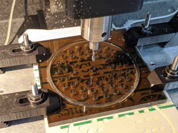
They’re done on the Sherline, because it has real clamps:
CNC Sink Strainer – on Sherline
Four tabs eliminated the need to reclamp the stock before cutting the perimeter, but I should have ramped, not plunged, through the final cut between the tabs:
CNC Sink Strainer – tab surface fracture
The handles come from the same chunk of hex acrylic as before, eyeballed to length, tapped 8-32, and secured with acrylic adhesive.
This file contains hidden or bidirectional Unicode text that may be interpreted or compiled differently than what appears below. To review, open the file in an editor that reveals hidden Unicode characters.
Learn more about bidirectional Unicode characters