Ed Nisley's Blog: Shop notes, electronics, firmware, machinery, 3D printing, laser cuttery, and curiosities. Contents: 100% human thinking, 0% AI slop.
Category: Software
General-purpose computers doing something specific
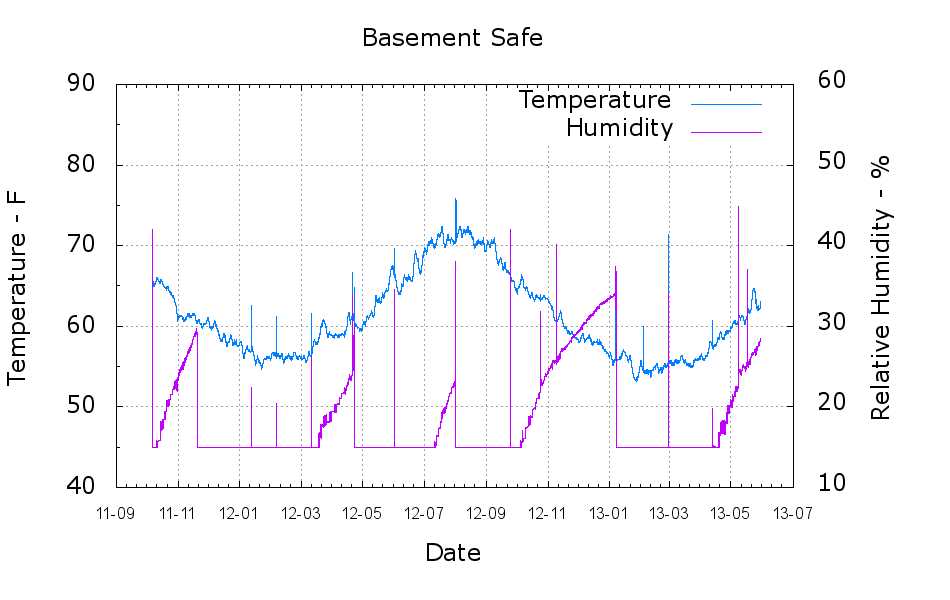
A plot of the temperature and humidity inside the basement safe over the last year-and-a-half:
Basement Safe
The tray of silica gel (or whatever those granules might be) holds the humidity firmly at 14 to 15 %, at least with a simple masking tape seal around the door opening that dates back to early 2012. Less water vapor gets through the door during the winter, due to the lower basement humidity when it’s cold outside, but it looks like four regenerations per year with just under a kilogram of desiccant in the tray.
Ordinarily, it’d be time for those granules to endure another oven session, but I just picked up a bunch of real silica gel beads and must conjure up some porous bags.
The Bash / Gnuplot script that cleaned the CSV files and produced the plot:
#!/bin/sh
#-- overhead
export GDFONTPATH="/usr/share/fonts/truetype/"
base="${1%.*}"
echo Base name: ${base}
ofile=${base}.png
tfile=$(tempfile)
echo Input file: $1
echo Temporary file: ${tfile}
echo Output file: ${ofile}
#-- prepare csv Hobo logger file
sed 's/^\"/#&/' "$1" | sed 's/^.*Logged/#&/' | sed 's/ ,/,/' | sed 's/\/\([0-9][0-9]\) /\/20\1 /' > ${tfile}
#-- do it
gnuplot << EOF
#set term x11
set term png font "arialbd.ttf" 18 size 950,600
set output "${ofile}"
set title "${base}"
set key noautotitles
unset mouse
set bmargin 4
set grid xtics ytics
set timefmt "%m/%d/%Y %H:%M:%S"
set xdata time
set xlabel "Date"
set format x "%y-%m"
#set xrange [1.8:2.2]
set xtics font "arial,12"
#set mxtics 2
#set logscale y
set ytics nomirror autofreq
set ylabel "Temperature - F"
set format y "%3.0f"
set yrange [40:90]
set mytics 2
set y2label "Relative Humidity - %"
set y2tics nomirror autofreq
set format y2 "%3.0f"
set y2range [10:60]
#set y2tics 32
#set rmargin 9
set datafile separator ","
#set label 1 "label text" at 2.100,110 right font "arialbd,18"
#set arrow from 2.100,110 to 2.105,103 lt 1 lw 2 lc 0
plot    \
    "${tfile}" using 2:3 axes x1y1 with lines lt 3 title "Temperature",\
    "${tfile}" using 2:4 axes x1y2 with lines lt 4 title "Humidity"
EOF
Because I want to measure several fairly high temperatures in and around the extruder with the LinuxCNC controller for the M2, I need a multi-channel thermocouple input. LinuxCNC’s hal_input interface module exposes the values produced by USB HID peripherals as HAL pins, which seems to be a nice way to add devices. A bit of searching revealed the TC4 Arduino Shield four-channel thermocouple + four-channel thermistor + assorted I/O board produced by the homeroasters.org folks as part of their DIY coffee roast controller.
The gotcha: ordinary Arduino boards cannot (without extraordinary effort) become USB HID peripherals, as their USB interface works only as a serial data device. The solution: the new-ish Arduino Leonardo has an on-chip USB interface that can act as a USB HID peripheral as well as the usual serial device.
Dan Newman, of Sailfish firmware fame, conjured up an a Arduino program (which, IMO, is far more complex than a mere sketch) that provides both a human-readable terminal interface and a LinuxCNC HAL-compatible USB HID interface using the Leonardo’s USB capabilities; the TC4Server project repository is on my GitHub account to keep it close to all the other stuff that should appear over the course of this project. His firmware builds on the libraries for the homeroaster’s tc4-shield Google Code project, but is intended for use with LinuxCNC, rather than as part of an Arduino controller.
It’s worth noting that the Leonardo has a mere 32 kB of program storage, so the extensive help documentation built into the program helped prevent feature creep.
Although I’m not yet using LinuxCNC with the M2, I can use TC4-Server’s serial terminal interface to read four channels of thermocouple data to help figure out what’s going on with the M2’s extruder thermistor. The TC4 shield has screw terminals for the thermocouples, but I also added a Proto ScrewShield board for thermistor resistors and easier connections:
TC4 on ProtoScrewShield on Leonardo
The TC4 Shield PCB layout assumes it’s being used with the original Arduino series of boards that bring the I2C (aka I2C, IIC, etc) SDA and SCL signals out on the A4 and A5 analog input pins, respectively. The newer Leonardo board brings SDA and SCL out in a separate header, so you must hotwire them across the board. The green and blue wires (stripped from a ribbon cable) accomplish that purpose: they’re plugged into the new Leonardo header through bent male header pins and clamped into the ScrewShield terminals. This assumes the Leonardo’s A4 and A5 pins remain as inputs, which is true for Dan’s firmware. If you actually need those pins for analog inputs, then you must remove the header pins that interconnect the boards and hotwire directly to the TC4 headers.
The TC4 shield includes an on-board temperature sensor that serves as the thermocouple cold-junction compensation reference. In my simple tests, the board has about 1 °C of self-heating, so I also use it to report the ambient temperature.
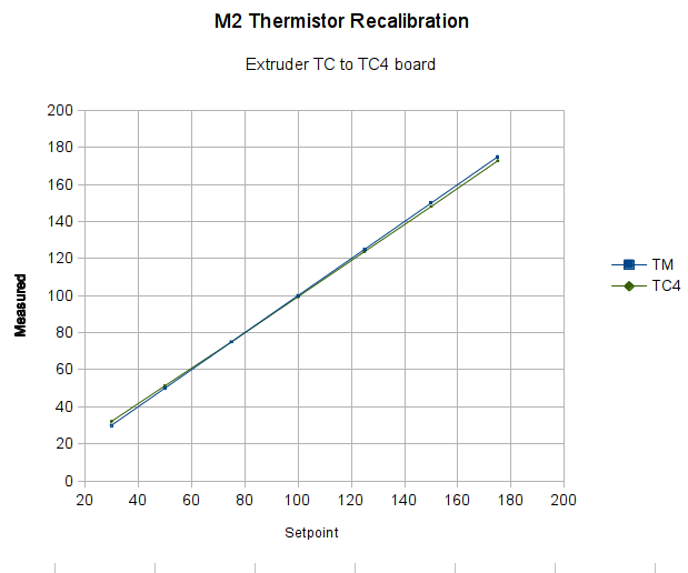
With all that in hand, I connected the thermocouple epoxied to the M2’s nozzle to the TC4 and re-ran the previous test with the modified thermistor table:
Rescaled extruder – thermocouple in TC4 board
The TC4 shield produces the same result as the Fluke meter with the same thermocouple, so we know those results will be consistent.
The modified thermistor table produces results that overlay thermocouple data. The questions come down to the accuracy of the thermocouple and whether bending the thermistor table actually represents an inherent property of the thermistor or just compensates for another problem.
Part of my motivation for using thermocouples, rather than thermistors, is that thermocouples avoid the whole dance of matching a given thermistor with a set of properties. Given the uncertain provenance of most thermistors, I have no reason to believe any of them match their alleged datasheets…
The Marlin firmware used by the M2 has these thermistor selections in Configuration.h:
//// Temperature sensor settings:
// -2 is thermocouple with MAX6675 (only for sensor 0)
// -1 is thermocouple with AD595
// 0 is not used
// 1 is 100k thermistor
// 2 is 200k thermistor
// 3 is mendel-parts thermistor
// 4 is 10k thermistor !! do not use it for a hotend. It gives bad resolution at high temp. !!
// 5 is ParCan supplied 104GT-2 100K
// 6 is EPCOS 100k
// 7 is 100k Honeywell thermistor 135-104LAG-J01

#define TEMP_SENSOR_0 1
#define TEMP_SENSOR_1 1
#define TEMP_SENSOR_2 0
#define TEMP_SENSOR_BED 1
The first table in thermistortables.h looks like this:
The OVERSAMPLENR constant determines the number of successive ADC samples added together into a single value, which is then used to search the table for the corresponding entry. The table entries are pairs of: {nominal ADC value * number of samples, temperature in C}
which means that if we know the temperature, we can work backwards to find the ADC value and then compute the actual thermistor resistance.
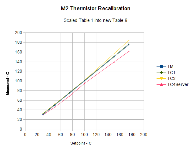
However, before doing that, I created a modified version of the thermistor table that simply scales the temperatures down by 0.878:
I inserted that table, changed the thermistor selection, reloaded the firmware, and ran the same test as before, which produced this result:
Rescaled extruder thermocouple
The stock thermistor and the thermocouple now report essentially the same values, which is entirely due to the new table. The two additional lines come from two more thermocouples taped to the nozzle and dangling downward toward the platform:
M2 – Hot end with additional thermocouples
Given that I simply taped those thermistors in place, they don’t contact the nozzle nearly as well as the epoxied sensors. The fact that one reads a bit higher and the other much lower could be explained by handwaving, but one possibility is that the various thermocouples don’t quite agree with each other.
Turns out that there’s no difference between the Mac and PC versions of the Logitech Dual Action Gamepad:
Logitech Dual Action Gamepads – Mac vs PC
I picked up a Mac version cheap from the usual eBay seller and discovered that LinuxCNC / HAL was perfectly happy. That wasn’t too surprising; they have the same model and part numbers. Most likely, the only difference was the CD and maybe the Quick Start Guide that I didn’t get in the opened retail box…
So now I have either a hot backup for the Joggy Thing or one for a different box.
Most likely, it was cheap because nobody wants a blue-and-black peripheral next to their shiny white Mac…
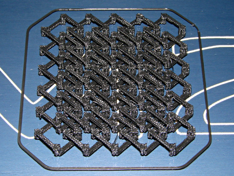
This is a subtractive version of Zomboe’s Chainmail, built by removing chunks from a solid rectangle the size of one link:
Chain Mail Link – Subtractive
Until what’s left is, indeed, a single link:
Chain Mail Link
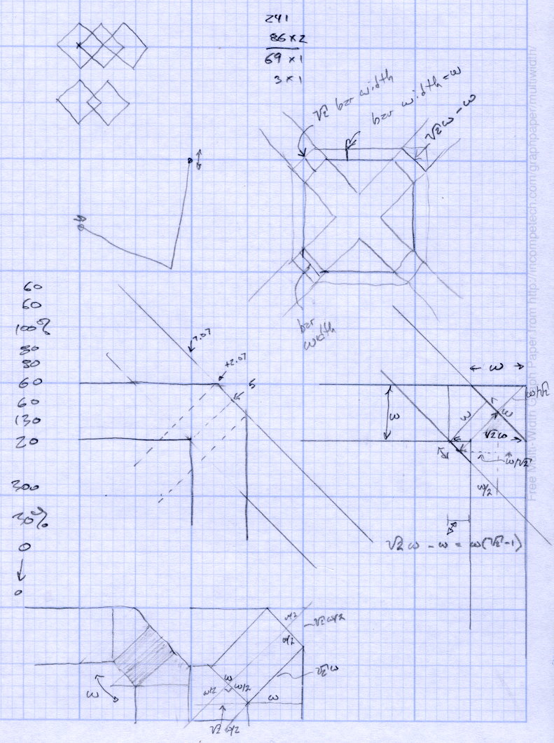
The pillars in the original model weren’t nearly large enough; Slic3r omitted them from the G-Code. They’re now as wide as the bars and √2 times that width long, which means they actually get a bit of fill.
Then a pair of nested loops replicates that link across the entire fabric:
Chain Mail Sheet
That technique didn’t work with Skeinforge (because it sent the nozzle scampering all over each layer, knocking things loose) and it didn’t work with Slic3r 0.9.8 (because it had problems with bridges), but Slic3r 0.9.10, hot from github, produced good results:
Chain Mail – as built
There were some strings connecting adjacent links, but a few minutes with a flush cutter solved that. Retraction was 1 mm at 80 mm/s = 480 mm/min, which seems to work fine in other contexts, but adjacent links fell inside the 1 mm minimum distance setting I’d been using. That’s now down to 0.5 mm, which should suffice for nearly everything.
The M2 sounded like I was hitting it with a hammer: each of the 480 pillar layers (!) required a quick squirt and a retraction, followed by a 500 mm/s move. Worked fine and didn’t miss a step anywhere along the way.
A view from the bottom shows it really is flexy:
Chain Mail – bottom
I used zero perimeter threads on these tiny links, which means you can see the ripply edges of the second layer that was crosswise to the length of the link bars. Next time, I’ll try one perimeter thread, which should smooth that out.
The links stuck to the glass like they were glued, which, indeed, they were: White Rain Unscented Extra Hold Hairspray in a pump bottle (either they didn’t have Maximum Hold pump spray or I couldn’t see it). I’m not a big fan of aerosol anything and decided to try wiping the stuff across the platform glass, rather than filling the air with a fine mist and getting some on the glass. Seems to work, but more examples are needed…
Because it seems there’s no good support for separate X sessions with dual monitors these days, the landscape and portrait monitors on my desk represent viewports into a larger pixel array within a single X session. As a consequence, it’s entirely possible to slide windows across the gutter between the two displays (generally producing an essentially unusable result), but one cannot flip through workspaces on only one monitor.
Worse, some programs seem to have trouble remembering that they were last seen on the portrait monitor, so I must rearrange the windows at the start of every session. First world problem, yeah, but still annoying.
I’d previously used devilspie to force windows to their proper places across monitors, sessions, and workspaces, but its s-expression syntax was impenetrable and I eventually gave up using it.
A fork (or continuation or something) called devilspie2 uses lua scripts that I can both read and write. It’s an Ubuntu package and easy to set up.
A typical script in ~/.config/devilspie2 looks like this:
if (get_application_name()=="Firefox") then
   set_window_geometry(0,0,1300,1200);
   maximize_vertically();
end
Putting Adobe Reader on the portrait monitor looks about the same:
if (get_application_name()=="acroread") then
   unmaximize();
   set_window_geometry(2561,0,1000,100);
   maximize();
end
Set /usr/bin/devilspie2 as an auto-started program and it Just Works…
set port /dev/ttyACM0
set baudrate 115200
set build_dimensions 200x240x195-100-120+0
set temperature_abs 200
set last_bed_temperature 70.0
set last_temperature 155.0
set xy_feedrate 30000
set z_feedrate 2500
set e_feedrate 300
set last_file_path /mnt/bulkdata/Project Files/Thing-O-Matic/Calibration
set temperature_pla 165
set preview_grid_step1 10
set preview_grid_step2 20.0
set preview_extrusion_width 0.4
set bedtemp_pla 70
Line 3 sizes the preview and offsets the XY=0 origin to the center of the plot.
The 200 mm X axis dimension is slightly larger than the actual 195 mm buildable area on the platform, but if the object gets that close to the maximum size, this isn’t the place to discover it.
The 240 mm Y axis dimension is slightly shorter than the actual 250 mm buildable area and slightly larger than the distance between the snouts of the bulldog clips holding the glass plate to the heater. In this case, the object can slightly exceed the preview size if it fits between the clips.
Lines 12 and 13 produce a relatively coarse grid that’s both meaningful and easy on the eyes, with the XY dimensions in Line 3 producing a major grid line crossing at the origin where it should be: